Transcript
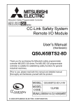
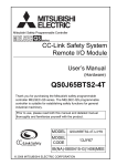
Mitsubishi Safety Programmable Controller
MELSEC-QS Series
Machinery Directive (2006/42/EC) Compliance
BCN-P5767-A
Thank you for purchasing the Mitsubishi safety
programmable controller MELSEC-QS series.
The MELSEC-QS series programmable controller is
suitable for establishing safety functions for general
industrial machinery and complies with the Machinery
Directive (2006/42/EC).
Before using this product, please read this manual, the
relevant manuals, the manuals for standard programmable
controller, and the safety standards carefully and pay full
attention to safety to handle the product correctly.
Product
Name
Model
CC-Link
Safety
QS0J65BTS2system
4T
remote I/O
module
*1
A safety output module connected to
external devices. The module has
four safety output points and sends/
receives safety data to/from the
safety programmable controller over
CC-Link Safety.
S-mark is a safety certification issued by Korea Occupational
Safety and Health Agency (KOSHA).
Product
Name
Model
Description
A unit where a safety CPU module,
safety power supply module, and CCLink Safety system master module
are mounted
An S-mark*1 certified safety main
QS034B-K
base unit
A module which is mounted on a
QS061P-A1
safety main base unit and supplies
100VAC to the system
A module which is mounted on a
Safety
QS061P-A2
safety main base unit and supplies
power
200VAC to the system
supply
module
An S-mark*1 certified safety power
QS061P-A1-K
supply module (100VAC)
An S-mark*1 certified safety power
QS061P-A2-K
supply module (200VAC)
A module which is mounted on a
QS001CPU
safety main base unit and performs
Safety
logic operations for safety control
CPU
module
An S-mark*1 certified safety CPU
QS001CPU-K
module
A module which is mounted on a
CC-Link
QS0J61BT12
safety main base unit and establishes
Safety
connection to CC-Link Safety
system
master
An S-mark*1 certified CC-Link Safety
QS0J61BT12-K
module
system master module
A safety I/O module connected to
external devices. The module has
eight safety input points and four
QS0J65BTB2safety output points, and sends/
12DT
receives safety data to/from the
safety programmable controller over
CC-Link
CC-Link Safety.
Safety
system
QS0J65BTB2- An S-mark*1 certified CC-Link Safety
remote I/O 12DT-K
system remote I/O module
module
A safety input module connected to
external devices. The module has
QS0J65BTS2- eight safety input points and sends/
8D
receives safety data to/from the
safety programmable controller over
CC-Link Safety.
Safety
main base
unit
No.
3)
4)
5)
6)
*1
QS034B
Application
Indicates the operating status of the CPU
module.
On: The module is in the RUN status (the
module is in operation).*1
Off: The module is in the STOP status (the
module is not operating) or a stop error
RUN LED
has been detected.
(green)
Flashing: A program and parameters are
written to the module which is in
the STOP status and then the
RUN/STOP/RESET switch is
changed from STOP to RUN.
(Flashing interval: on 200ms/off
200ms)
On: A self-diagnostics error that will not stop
module operation, except for a battery
error, has been detected.*1
Off: The module is operating normally.
Flashing: A self-diagnostics error that will
ERR. LED (red)
stop module operation has been
detected. (Flashing interval: on
200ms/off 200ms) Or, the module
has been reset. (Flashing interval:
on 60ms/off 60ms)
On: The annunciator (F) turns on.*1
USER LED (red)
Off: The module is operating normally.
On: A battery error has occurred due to the
BAT. LED
CPU battery voltage drop.*1
(yellow)
Off: The module is operating normally.
The LED also turns on during the initial processing (such as
self-diagnostics) immediately after power-on or reset.
QSCPU User's Manual (Hardware Design,
Maintenance and Inspection)
QSCPU User's Manual (Function Explanation,
Program Fundamentals)
CC-Link Safety System Master Module User's
Manual
CC-Link Safety System Remote I/O Module
User's Manual
GX Developer Version 8 Operating Manual
GX Developer Version 8 Operating Manual
(Function Block)
GX Developer Version 8 Operating Manual
(Safety Programmable Controller)
QSCPU Programming Manual (Common
Instructions)
QSCPU Programming Manual (Safety FB)
1)
2)
RUN LED
ERR. LED
3)
MST LED
4)
L RUN LED
5)
L ERR. LED
6)
7)
SD LED
RD LED
Application
On: The module is operating normally.
Off: The module has detected a WDT error.
Off: Communication has been failed in all
stations.
This LED turns on when one of the
following errors has occurred.
•There are more than one master
station on the same network.
•Parameter setting is wrong.
•The data link monitoring timer timed
out.
•The cable is disconnected or the
transmission path is affected by noise.
Flashing: A communication failure has been
detected in one of the stations or
the remote station numbers are
overlapped.
On: The module is operating as master
station. (The module is controlling data
link.)
On: The module is performing data link.
On: A communication error has occurred in
the master station.
Flashing irregularly:
A terminating resistor is not attached or
the module and/or the CC-Link
dedicated cable is affected by noise.
On: The module is sending data.
On: The module is receiving data.
(4) CC-Link Safety system remote I/O module
Refer to the user's manual (hardware) provided with
each CC-Link Safety system remote I/O module.
Manual Number
(Model Code)
SH-080613ENG-D
(13JR90)
SH-080626ENG
(13JR92)
SH-080627ENG
(13JR93)
SH-080600ENG
(13JR88)
SH-080612ENG
(13JR89)
SH-080373E
(13JU41)
SH-080376E
(13JU44)
SH-080576ENG
(13JU53)
SH-080628ENG
(13JW01)
SH-080744ENG
(13JW05)
50mm
or more
Programmab
Control
panel
5mm or more
(c) When installing a programmable controller to a
control panel, do not mount any module in the
rightmost slot of the base unit.
Before uninstalling, remove the module mounted
in the rightmost slot of the base unit.
Door
20mm
or more
30mm
or more
*1
Safety Standards
IEC61508:1998 to 2000, ISO13849-1:2006,
International
IEC61131-2:2007, IEC61000-6-2:2005, IEC610006-4:2006
EN954-1:1996, EN ISO13849-1:2008, EN61131Europe
2:2007,
EN61000-6-2:2005, EN61000-6-4:2007
North America UL508
5mm or more
(4) CC-Link Safety system remote I/O module
For the installation of CC-Link Safety system remote
I/O modules, refer to the user's manual (hardware)
provided with each module.
A clearance required when the wiring duct is 50mm or less in
height. A 40mm or more clearance is required when the wiring
duct is longer.
(2) Module mounting orientation
(a) Mount modules in the following orientation to
ensure good ventilation for heat release.
6. Module Status after Power-on and LED
Indication
A safety programmable controller performs initial
processing (such as self-diagnostics) after power-on or
reset. The LEDs of each module indicate the module
operating status after initial processing.
(b) Do not mount modules in the following
orientations.
(1) Safety power supply module
No.
1)
Region
Name
Replace the module or unit according to the following
replacement cycle.
Replacement Cycle
5 years
10 years
10 years
10 years
5 years
7. Precautions for Use
PFD/PFH = A + B + C + D ....Calculation formula of PFD/
PFH
A
B
B1
B2
C*1
D*1
*1
Application
On (green): The module is operating
normally. (5VDC output or
momentary power failure within
20ms)
Off: • AC power is supplied, but the module
has been failed. (5VDC output failure,
overload, internal circuit failure or fuse
blown)
• AC power is not supplied.
• Power has been failed (including
momentary power failure 20ms or
longer).
(2) Safety CPU module
Upside-down mounting
No.
(a) Install a base unit on a flat surface.
If the surface is not flat, the printed circuit board
is distorted, resulting in malfunction of the
modules mounted.
(b) If there is a vibration source, such as an
electromagnetic contactor or no fuse breaker,
separate the control panel or keep enough
clearance from the vibration source to install the
programmable controller.
Name
1)
ALIVE LED
(green)
2)
TEST LED
(yellow)
Application
On: The module is operating normally.*1
Off: The module has detected a hardware
WDT error. (The ERR. LED turns on.)
Indicates the operating mode of the CPU
module.
On: The module is in TEST MODE.*1
Flashing: The mode is switched from TEST
MODE to SAFETY MODE. The
LED turns off after the module is
reset. (Flashing interval: on
200ms/off 200ms)
Off: The module is in SAFETY MODE.
8. EC Declaration of Conformity
Users must prove that their entire safety system complies
with the safety standards and the Machinery Directive. The
third-party certification organization will validate the safety
of product for the entire safety system, including a safety
programmable controller and safety components.
To establish a safety system, calculate the target failure
measure (PFD/PFH) for each safety application (safety
function) based on the PFD/PFH values of the safety
programmable controller and connected safety
components. The target failure measure (PFD/PFH) is the
reliability target value for each Safety Integrity Level (SIL)
defined in IEC61508 and can be calculated by the following
formula.
Variable
POWER LED
Upward/downward mounting
(3) Installation precautions
4. Module/Unit Replacement
Module/Unit
Safety power supply module
Safety CPU module
Safety main base unit
CC-Link Safety system master module
CC-Link Safety system remote I/O module
Vertical mounting
Definition
Total PFD/PFH of the safety CPU module, safety power
supply module, safety main base unit, and CC-Link
Safety system master module
PFD/PFH of the CC-Link Safety system remote I/O
module
(1) When safety input device(s) and safety output
device(s) are connected to the same CC-Link Safety
system remote I/O module: B=B1
(2) When safety input device(s) and safety output
device(s) are connected to different CC-Link Safety
system remote I/O modules: B=B1+B2
PFD/PFH of the CC-Link Safety system remote I/O
module to which safety input device(s) is connected
PFD/PFH of the CC-Link Safety system remote I/O
module to which safety output device(s) is connected
PFD/PFH of safety input device(s)
PFD/PFH of safety output device(s)
For the values, refer to the manual for the safety component
used.
EC Declaration of Conformity
Manufacturer:
Mitsubishi Electric Corporation, Nagoya Works
Address:
Products:
1-14, 5-chome, Yada-Minami, Higashi-ku, Nagoya 461-8670,Japan
Type:
Programmable Controller
(Open Type equipment, Installation category II)
Model: QS-Series
(Applicable units identified in Appendix)
These products comply with the following European directives:
Directive
2006/42/EC
Name
Machinery Directive
Further details of conformity to these directives are contained in the appendices (BCN-P9999-****).
This declaration is based on the conformity assessment of following Notified Body:
TÜV RHEINLAND INDUSTRIE SERVICE GMBH - TÜV Rheinland Group
Am Grauen Stein
D-51105 Köln
Germany
Phone : +49:221:8060
Fax : +49:221:806114
Email : [email protected]
Website : http://www.tuv.com
NB 0035
Authorised Signature:
(First name, Last name)
Senior Manager, FA System Department
Date: (date)
(signature)
Authorised Representative: Mitsubishi Electric Europe BV
in the European Community Gothaer Strase 8, 40880 Ratingen, Germany
through Responsible person
Signature:
(First name, Last name)
Division Manager,
FA European Development Center
FA European Business Group
Date: (date)
(signature)
The appendices are part of this declaration. This declaration certifies the conformity with the directives mentioned,
but does not contain any warranted qualities. The installation, usage and safety directions of the product
documentation have to be observed.
The following tables show the PFD/PFH values for the
safety programmable controller.
Module/Unit
Total PFD/PFH of the safety CPU module,
safety power supply module, safety main
base unit, and CC-Link Safety system
master module*2
PFD/PFH of the CC- QS0J65BTB2-12DT
Link Safety system QS0J65BTS2-8D
remote I/O module QS0J65BTS2-4T
PFD
1.39
10-4
PFH(/h)
4.95
10-9
2.57 10-5 1.15 10-9
1.68 10-5 7.46 10-10
1.68 10-5 7.46 10-10
Module/Unit
PFD
PFH(/h)
Total PFD/PFH of the S-mark certified safety
CPU module, safety power supply module,
1.28 10-4 4.72 10-9
safety main base unit, and CC-Link Safety
system master module*2
PFD/PFH of the Smark certified CCQS0J65BTB2-12DT0.27 10-4 1.21 10-9
Link Safety system
K
remote I/O module
*2
Appendix
QS-Series Programmable Controllers
Range of products:
QS001CPU
QS034B
QS034B-E
QS061P-A1
QS061P-A2
QS0J61BT12
5
5
5
5
5
5
QS0J65BTB2-12DT
QS0J65BTS2-8D
QS0J65BTB2-4T
5
5
5
QS001CPU-K
QS034B-K
QS061P-A1-K
QS061P-A2-K
QS0J61BT12-K
QS0J65BTB2-12DT-K
5
5
5
5
5
5
The conformity of the above mentioned products with the regulations of the directive 2006/42/EC for machinery is
shown by the application of a Technical Construction File. This is supported by selected product tests to the
following standards directly and indirectly (when Generic standards are used).
Note: The mentioned products must be used as directed by the associated documentation in order to provide full compliance.
Harmonized European Standards
Reference No.
EN ISO13849-1
Date of Issue
2008
Modules marked with a mark 5 have been tested to EN ISO13849-1(2008)
Revision Record
*
15/12/09
Signature
The list is created.
The number of CC-Link Safety system master modules does
not affect the PFD and PFH values.
For details on the target failure measure (PFD/PFH), refer
to the Safety Application Guide.
50mm
or more
Device
(such as contactor and relay)
30mm or
more*1
Use the product according to the following safety
standards.
Name
Name
Ceiling of the control panel, wiring
duct or any other parts
100mm
or more
3. Safety Standards
(3) CC-Link Safety system master module
No.
(1) Installation position
Keep the clearances shown below between the top/
bottom faces of the modules and the control panel
or other parts so that good ventilation is ensured
and the modules can be easily replaced.
The following lists the safety programmable controller
relevant manuals.
Order each manual as needed, referring to the list.
Safety Application Guide
1. Safety Programmable Controller Product
List
When installing a programmable controller to a control
panel or similar, fully consider its operability, maintainability,
and environmental resistance. For details, refer to the
QSCPU User's Manual (Hardware Design, Maintenance
and Inspection).
2. Relevant Manuals
Manual Name
In addition, keep the clearances shown below
between the programmable controller and
devices (such as contactors and relays) to avoid
being affected by radiated noise or heat.
• In front of the programmable controller:
100mm or more
• On the right or left of the programmable
controller: 50mm or more
5. Installation
Description
BCN-P9999-****