1
SurfMaster 4 User Manual
END USER LICENSE AGREEMENT
THIS IS A LEGAL AND BINDING AGREEMENT ("AGREEMENT") BETWEEN YOU, THE AUTHORIZED
USER OF THE CAD BEST LTD. PROPRIETARY SOFTWARE AND DOCUMENTS KNOWN AS THE CAD BEST
LTD. SURFMASTER 4 IN ITS DOWNLOADED OR CD FORMAT (THE "FILES"), BY CLICKING ON THE
"I ACCEPT" BUTTON AND PURCHASING THE USE OF THE FILES, YOU ARE CONSENTING TO BE
BOUND BY THIS AGREEMENT. IF YOU DO NOT AGREE TO ALL OF THE TERMS OF THIS AGREEMENT,
CLICK ON THE "I DISAGREE BUTTON".
1. Limited Use License. In consideration of your agreement to be bound by the terms
of this Agreement, CAD BEST Ltd. hereby grants to you a non-exclusive, nontransferable license to download /or purchase on a CD/ a File or Files as
appropriate to the fee paid, to use these File(s) internally on a single computer,
use the file(s) and distribute the results. All rights not expressly granted herein
are retained by CAD BEST Ltd. And its licensors, as the case may be.
2. Limitations. The Files are protected by international copyright laws and
international treaties. You may not modify or prepare derivative works from the
Files. You may not copy (except as set forth herein), sell, rent, lease,
sublicense, assign, loan, time-share, share through an internal computer network or
otherwise transfer or distribute (except as set forth herein) the Files. You may
make a reasonable number of copies of the Files for backup or archival purposes
only, so long as CAD BEST Ltd. copyright notices are reproduced on such copies. You
shall not, and shall not permit a third party to remove any identification,
copyright or other notice from the Files.
3. Ownership of Files. This license is not a sale of the Files or any copy thereof.
All worldwide ownership of and rights, title and interest in and to the Files, and
all copies and portions thereof, including without limitation, all copyrights,
trademark rights, trade secret rights and other proprietary rights therein and
thereto, are and shall remain exclusively in CAD BEST Ltd. and its licensors.
4. Termination. The license granted herein is effective until terminated. The
license will terminate immediately without notice if you fail to comply with any
material provisions of this License Agreement. Upon termination you shall destroy
or return to CAD BEST Ltd. all copies of the Files or portions thereof. The
provisions of this License Agreement other than the license grant herein, shall
survive termination.
5. Disclaimer. THE CAD BEST LTD. PROVIDES THE DOCUMENTS "AS IS". THE CAD BEST LTD.
MAKES NO WARRANTIES WITH RESPECT TO THE DOCUMENTS OR THE AVAILABILITY OF CAD BEST
LTD. SITE ON THE WORLD WIDE WEB, EXPRESS, IMPLIED OR STATUTORY, AND THE CAD BEST
LTD. EXPRESSLY DISCLAIMS ALL OTHER WARRANTIES, INCLUDING BUT NOT LIMITED TO THE
IMPLIED WARRANTIES OF DUE CARE, SATISFACTORY QUALITY, NON-INFRINGEMENT OF THIRD
PARTY RIGHTS, MERCHANTABILITY AND FITNESS FOR A PARTICULAR PURPOSE.
6. Limitations of Liability. YOU AGREE THAT IN NO EVENT WILL THE CAD BEST LTD. OR
ITS LICENSORS BE LIABLE TO YOU OR ANY THIRD PARTY CLAIMING THROUGH YOU FOR THE
RESULTS OF YOUR USE OF THE DOCUMENTS, YOUR INABILITY OR FAILURE TO CONDUCT YOUR
BUSINESS, OR FOR ANY SPECIAL, INCIDENTAL, CONSEQUENTIAL, INDIRECT OR PUNITIVE
DAMAGES EVEN IF THE CAD BEST LTD. HAS BEEN ADVISED OF THE POSSIBILITY OF SUCH
DAMAGES. THE CUMULATIVE LIABILITY OF CAD BEST LTD. AND ITS LICENSORS TO YOU FOR ALL
CLAIMS ARISING UNDER THIS AGREEMENT, WHETHER IN CONTRACT OR TORT, INCLUDING
NEGLIGENCE, SHALL NOT EXCEED THE LIST PRICE OF THE DOCUMENTS.
7. Autodesk, AutoCAD are registered trademarks or trademarks of Autodesk, Inc., in
the USA and other countries.
Copyright © 2013 CAD BEST Ltd.
SurfMaster 4 User Manual
Table of Contents
Introduction
4
Basic Concepts
6
SurfMaster Commands List
10
SurfMaster Commands Description
12
Your Maiden Flight with SurfMaster
34
Some Examples
50
Last Minute Notes
52
Installation and maintenance
53
Copyright © 2013 CAD BEST Ltd.
SurfMaster 4 User Manual
Introduction
The proposed SurfMaster 4 software pack is intended to assist in sheet design construction.
The design uses thin 3D surfaces that can be obtained through the appropriate bending of
corresponding planar cutouts.
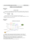
Original
surface
Unfolded
cutout
Fig. 1. 3D surface and its flattened cutout
The 3-dimensional surfaces produced in this way have a single concavity because the
bending does not cause any volume deformation. These surfaces are also known as
“developable surfaces”.
If more complicated 3D surfaces with double concavity should be recreated, they can be
approximated with some sequence of segments that are single concavity developable
surfaces.
Very often the shapes of a complex object can be represented by definition curves, obtained
by intersecting of some set of simple developable surfaces.
As a rule, the object surfaces form something like a skin. The strength of this skin is ensured
using certain reinforcing elements. Such elements are cross-sections called “formers”, whose
geometry is bound to a given construction.
There are also many linear elements representing details that are also bound to the
construction.
Typical sheet design tasks in engineering involve the use of standard parts and solutions that
Copyright © 2013 CAD BEST Ltd.
SurfMaster 4 User Manual
are based on some given parameters. This approach is known as a parametric design and is
ideal for the most common industrial design tasks, where the use of standard elements is
preferable if not obligatory.
However, the sets of predetermined design solutions of other software packs are often
unable to handle all of the tasks that may be faced in practice. The world around us is large
and multifarious and cannot be constrained to a certain set of categories, such as pipes,
knees, adapters and toggles.
The main purpose of the SurfMaster pack is to solve such irregular design tasks by using
user-defined free-edge developable surfaces. And while the software pack can be used also
for processing all standard elements, the adding of the finishing touches – dimensioning and
optimal positioning of the produced cutouts, is up to the user.
SurfMaster is not a stand-alone application. The most convenient environment for using
SurfMaster is AutoCAD.
It is highly recommended that the user be familiar with the basics of AutoCAD. These
include:
-
Drawing with precision
-
Editing and modifying AutoCAD drawing entities
-
Navigating in 3D space
Detailed knowledge of linear objects (i.e., lines, 2D and 3D polylines, splines, circles, ellipses
and arcs) is also recommended.
Copyright © 2013 CAD BEST Ltd.
SurfMaster 4 User Manual
Basic Concepts
SurfMaster uses 3D wireframe models for representing the design created. Wireframe
models consist of definition curves that define the edges of surfaces or segments. Almost all
AutoCAD linear entities (i.e., lines, 3D polylines, 2D normal, splined or fitted polylines,
splines, circles, ellipses, circular and elliptical arcs) can be used as definition curves. All of
these entities are approximated using 3D polylines that consist of straight segments. Thus,
the surfaces can be approximated with the sequence of triangles. To prevent the loss of
information during curve approximation, center marks are added to all circles, ellipses,
circular and elliptical arcs.
Once decomposed into a sequence of neighboring triangles, the surface can be unfolded
triangle by triangle and placed onto the XOY plane of the AutoCAD World Coordinate
System. In this way, it is possible to produce a cutout which corresponds to its parent
surface. Apart from two flattened definition curves, the cutout also contains two linear
edges. The first of these edges is considered the cutout’s baseline. The baseline and the
second line are also drawn between the surface definition curves in 3D space.
Although SurfMaster does not retain any internal information about definition curves,
surface cutouts and their definition curves, surface start marks are placed both on the
surface and on the cutouts making it easy for the user to obtain this information if needed.
Original
surface
SurfMaster
interpretation
Wireframe
model
Fig. 2. The actual object, its wireframe model and its SurfMaster interpretation
Copyright © 2013 CAD BEST Ltd.
Basic Concepts
It is also interesting to note that SurfMaster does not retain any geometrical information
about the surface and its cutout. If such information is required for further processing, such
as intersection or folding back, the information is obtained dynamically by recalculating the
geometry.
The surface can, of course, be generated as a native AutoCAD polyface mesh entity, which
can be also unrolled over the cutout. However, this is used for visualization purposes only.
The decomposition of the 3D surfaces into triangles form the basis for the geometric
calculations.
AutoCAD itself has very simple method of decomposition for creating ruled surfaces. It
divides the definition curves into an equal number of equidistant straight segments and
generates not triangles, but quadrangles. They are convenient only for visualization because
their normal vectors needed for calculation of illumination are calculated correctly despite
the fact, that quadrangles are not plain objects. If a similar decomposition has to be done
but to triangles, the adjacent triangles volume angles will change its sign consecutively and
something like a stair effect will appear.
SurfMaster uses more complicated optimization algorithms to produce surfaces with the
maximum smoothness possible.
The main triangles decomposing algorithm uses minimum of the integral concavity as criteria
and is set as default. The main algorithm for triangular decomposition uses the smallest
integral concavity and is set as default. It is great for working with non-twisted surfaces.
For twisted areas, such as those of spiral surfaces, better results can be obtained by using
natural optimization, which minimizes the integral deformation of the surface.
In certain cases, the option to use consecutive decomposition without optimization is also
provided.
Fig. 3. Curvature optimization mode on/off comparison
Copyright © 2013 CAD BEST Ltd.
SurfMaster 4 User Manual
SurfMaster users have the option of three different optimization modes for decomposition.
The mode used is displayed as a Roman numeral (I, II or III) within the start marks.
SurfMaster calculates the volume angle between each pair of triangles. If the angle is greater
than some preset value, a fold line and fold marks are drawn both in 3D and on the cutouts.
Finally, the decomposition triangles are drawn on a special sm_control layer. This allows
visual control to be exercised over the results. If the results are acceptable, the control
triangles can be deleted using the clear control (sm_cclear) command.
If the results differ from those expected, some troubleshooting should be done. This
involves: checking and possibly changing the direction of one of the definition curves,
splitting the surface into separate adjacent parts and changing the type of decomposition.
Surface
decomposition
Folding
line
Wireframe
model
Origin and
optimisation mode
mark
Folding
mark
Unfolded
cutout
Fig. 4. Using SurfMaster’s “Cutout” command to unfold a surface.
Since the 3D surfaces do not have defined front or back sides, their cutouts can appear to be
mirrored in the Y direction. Start marks help to keep it more clear.
Once successfully created, the surface/cutout pair can be used in future operations.
Very often, we consider some surfaces as geometric places of an object that we are
interested in. We can easily create these objects on the unfolded planar cutouts of these
surfaces and then can fold back them on their places in 3D space.
The intersect command calculates the intersection line(s) between two 3D segments both in
3D space and on their cutouts. Using this command, it is possible to obtain very complicated
intersection curves from easy-to-define surfaces. After using the refine command, these
curves can be used as definition curves for other surfaces.
Copyright © 2013 CAD BEST Ltd.
Basic Concepts
Intersection lines
Part 1
Part 2
Origin and
optimisation mode
marks
Cutout 1
Cutout 2
Fig. 5. Using the “intersect” command
SurfMaster also offers the possibility of producing a parallel projection of some set of linear
objects on the 3D surface in X, Y or Z direction.
Sometimes it is much easier to draw the necessary objects directly on the cutouts, because
only 2D drawing is needed. SurfMaster makes it possible to fold these objects back onto
their places on the parent surface in 3D space.
The same set of
polylines over the original
3D surface
Cutout produced
3D surface
Set of polylines
drawn on the cutout
/Note the way for
produsing sharp apex
surfaces, like cones
and pyramids/
Fig. 6. Drawing polylines directly on the cutout and folding them back over onto the
3D surface
Apart from the basic commands, SurfMaster also provides a set of auxiliary commands,
which at can be of help in creating a 3D model and in dealing with definition curves.
Copyright © 2013 CAD BEST Ltd.
SurfMaster 4 User Manual
SurfMaster Commands List
Commands for working with segments:
- Unfold /sm_unfold/. This command unfolds the segment and produces its planar cutout.
- Intersect /sm_interx/. This command creates the intersection line(s) between two
segments.
-Project planar entities onto a segment / SM_DRAWdir /, where “dir” stands for the
directions X, Y and Z. The resulting projections are rendered both in 3D and on the cutout.
- Fold back /sm_foldback/. It transfers everything drawn on the cutout back onto the source
segment in 3D space.
Commands for working with polyface meshes:
- Create polymesh surface /sm_pfmesh/
- Unroll polymesh /sm_unroll/
- Roll back polymesh /sm_rollback/
- Cut polymesh with closed contour /sm_cutmesh/
Commands for wireframe model construction:
- Create the 3D wireframe model using its parallel projection /sm_construct/
- Extract formers /sm_former/
- 3- or 4-point transformation /sm_transf_c and sm_transf_l/ using container or connecting
lines.
- Create container for transformation /sm_container/.
- Create connecting strips /sm_cstripe/
- Add fold marks /sm_fmark/
Commands for dealing with definition curves:
- Convert linear objects to 3D polylines /sm_pln3d/. This command converts lines, arcs,
circles, and 2D simple, fitted or splined polylines into 3D polylines in 3D space.
- Convert linear objects to 2D polylines /sm_pln2d/. This command projects all of the abovementioned entities onto the XOY plane.
- Refine polylines /sm_refine/. This command reduces the number of vertices to the
minimum needed for keeping the polyline’s shape.
Copyright © 2013 CAD BEST Ltd.
Commands List
- Resample polylines /sm_edist/. This command converts a linear drawing object into a 3D
polyline with the desired number of vertices. The option to preserve apexes is provided.
- Join linear objects /sm_joinpl/. This command joins segments and produces 3D polylines.
- Reverse order /sm_revord/. Since the order and direction of the internal representation of
the edges that define segments are important, this command makes it possible to change
them.
- Split contours /sm_split/. This command is useful for setting the origin of the cutout.
- Place the start mark /sm_smark/. This command shows the origin and direction of linear
drawing objects.
Auxiliary commands:
- SurfMaster Configuration /sm_config/. This is a tool that helps adjust SurfMaster’s
configuration settings according to the user’s preferences. It can be used to establish how
selection sets are created, to select optimization modes and to set certain important
parameters for using the SurfMaster software pack.
- Clear Control /sm_cclear/. This command deletes all the triangle sides visualized for
controlling the execution of the unfold and intersect commands. It is highly recommended
that the Control mode be on in order to avoid unexpected and unwanted results.
General Notes:
- Strictly follow the order of selecting objects during the command execution. Follow the
sequence shown on the command line.
- Use the cutout marks automatically placed at the origin of cutouts and on the 3D surfaces
for easy orientation.
- Use the sm_config command to set the desired parameters for some of the SurfMaster
commands.
Copyright © 2013 CAD BEST Ltd.
SurfMaster 4 User Manual
SurfMaster Commands Description
Unfold
SM_UNFOLD
This command unfolds a segment defined by its edges onto a planar cutout. To use it, you
should first create the definition curves of the edges represented the surface of the
segment.
The definition curves can be one of the following AutoCAD entities:
- lines
- 3D polylines
- 2D polylines containing straight or arc segments
- splined 2D or 3D polylines
- splines
- circles
- ellipses
- arcs (circular or elliptical)
Each of these entities can be used as is or can first be converted to 3D or 2D polylines using
the corresponding SurfMaster commands. When converting circles, ellipses and arcs, center
marks are automatically added to prevent the loss of information. Splines are refined
automatically.
Note that some AutoCAD commands, such as rectangle and polygon, produce 2D / LW
polylines. After being exploded, the helix entity appears as a spline.
To obtain a surface’s cutout, SurfMaster decomposes the 3D segment into a sequence of
triangles and places them on the XOY plane. Three different optimization modes can be used
for decomposition:
- Curvature optimization, which uses the minimum of the integral surface’s curvature as
criteria (I)
- Natural optimization, which uses the smallest potential energy of deformation (II)
- Sequential decomposition without optimization (III)
The first one is recommended and is set as the default.
Since the segment does not have defined front and back sides, the cutout may appear to be
mirrored in the Y direction.
The unfold command requires a selection set of 2 edges. The order in which they are
selected is important. ONLY one entity may be selected at a time.
Copyright © 2013 CAD BEST Ltd.
Natural optimisatiom
Curved optimisation
Commands Description
Developable surface
Result: Perfect!
Result: WRONG
Spirall
Result: WRONG!!!
Result: Acceptable
Fig. 7. Comparing the use of optimization modes on different surfaces
To create the selection set:
- Select the 1st definition curve of the surface.
- Select the 2nd definition curve of the surface.
- Press Enter to complete the selection set.
The cutout produced is attached to the cursor and can be dragged to the desired location.
If one of the definition curves is a straight line that touches one of the ends of the other
definition curve, the surface is interpreted as being conical.
The first edge selected will be the first edge on the produced cutout. It is recommended that
the following sequence be followed for the overall design: from left to right, from front to
back, and from bottom to top.
After creating the cutout, SurfMaster attaches it to the cursor. The user can then drag it to
the desired position. The decomposition is only illustrated if the control mode is set to ON.
SurfMaster finishes the command by drawing origin marks, fold marks and fold lines.
The origin marks, drawn both on the cutout and for the original surface in 3D space, contain
information about the optimization mode used, mirroring, the baseline and the order of the
definition curves. This information should be stored in case it is needed later when using
other SurfMaster commands, such as the intersect command, to work on the same surface
and its cutout.
Copyright © 2013 CAD BEST Ltd.
SurfMaster 4 User Manual
In the event that the results obtained differ from those expected, the following steps should
be taken:
- Check the origin and direction of the definition curves. Use the sm_revord command to
change their direction if needed, in order to avoid a basket effect.
- If the direction of the curves is correct, yet the result is still not as was expected, split the
curve into two or more parts using the sm_split command.
- If neither of the previous steps help /in the case of spiral surfaces /, change the
optimization mode to natural using the sm_config command.
Be sure that the appropriate values of the parameters affecting command execution are
properly set using the sm_config command.
The control triangles’ decomposition lines can be removed using the sm_cclear command.
Intersect
SM_INTERX
This command creates an intersection line(s) between two segments, defined by their edges,
and provides the option to have this line drawn on one or on both of their cutouts.
The settings and the order should be exactly the same as those used for the segments’
cutouts if they have already been created with the unfold command. The optimization mode,
baseline and the order of the definition can be obtained from the origin marks.
Below is an illustration of the process of triangular decomposition when the control mode is
ON.
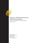
Fig. 8. Obtaining the intersection lines between surfaces
Copyright © 2013 CAD BEST Ltd.
Commands Description
The intersect command requires a selection set of two segments and, optionally, one or two
corresponding cutouts. The selection set, therefore, consists of two types of entities:
required and optional. ONLY one entity may be selected.
To create the selection set:
- Select the 1st curve of the 1st surface.
- Select the 2nd curve of the 1st surface.
- Select the 1st curve of the 2nd surface.
- Select the 2nd curve of the 2nd surface.
- Select the baseline of the 1st cutout (optional).
- Select the baseline of the 2nd cutout (optional).
- Press Enter to complete the selection set.
You can remove the decomposition lines of the control triangles using the sm_cclear
command.
It is highly recommended that the sm_refine command be used to reduce the number of
vertices in the resulting curves.
Copyright © 2013 CAD BEST Ltd.
SurfMaster 4 User Manual
Draw in direction X, Y or Z
SM_DRAWX
SM_DRAWY
SM_DRAWZ
These commands are similar and create a linear projection of the selected entities onto a
surface defined by its curves. The obtained intersection lines are drawn on the surface in 3D
space and, optionally, on its cutout.
Fig. 9. Drawing in direction Z
The settings and the order should be exactly the same as those used for the segments’
cutouts if they have already been created with the unfold command. The optimization mode,
baseline and the order of the definition curves can be obtained from the origin marks.
Each of the commands requires two selection sets. The first set includes the surface’s
definition curves and, optionally, the surface‘s cutout base. The other one includes the
entities to be projected. ONLY one entity may be selected at a time for the first selection set.
To create the selection sets:
- Select the 1st curve.
- Select the 2nd curve.
- Select the baseline of the cutout (optional).
- Press Enter to complete the first selection set.
- Select the entities to be projected.
- Press Enter to complete the second selection set.
Copyright © 2013 CAD BEST Ltd.
Commands Description
You can remove the decomposition lines of the control triangles using the sm_cclear
command.
Fold back
SM_FOLDBACK
This command takes the entities drawn on the cutout created using the unfold command
and folds them back onto the parent segment.
Be sure to use the same settings and order as the ones used during the generation of the
cutout.
The optimization mode, baseline, mirroring and the order of the definition curves can be
obtained from the origin marks.
Fig. 10. Using the “fold back” command to create a spiral surface
The fold back command requires a selection set composed of the definition curves, the
cutout base and the entities drawn on the cutout that is to be folded back into 3D. ONLY one
entity may be selected at a time.
To create the selection set:
- Select the 1st curve of the parent surface.
- Select the 2nd curve of the parent surface.
- Select the baseline of the cutout.
Copyright © 2013 CAD BEST Ltd.
SurfMaster 4 User Manual
- Select the entities that should be folded back.
- Press Enter to complete the selection set.
If the unfolded entities are closed contours, the origin of the resulting contours may differ.
Clear control
SM_CCLEAR
This command permanently deletes all entities in the sm_control layer which were created
using SurfMaster commands
Draw polyface mesh
SM_PFMESH
This command creates a polyface mesh representing a surface, defined by its definition
curve. The polyface mesh is used for visualization purposes only. It can be unrolled onto the
surface’s cutout, cut by some closed contour and rolled back.
If you have already used this surface, be sure to use the same settings and order as those in
the previous step.
The draw polyface mesh command requires a selection set of 2 edges. The order in which
they are selected is important. . ONLY one entity may be selected at a time.
Copyright © 2013 CAD BEST Ltd.
Commands Description
Fig. 11. Using polyface meshes for visualization
To create the selection set:
- Select the 1st definition curve.
- Select the 2nd definition curve.
- Press Enter to complete the selection set.
The decomposition of the surface into triangles depends on the optimization mode selected.
It should be the same as those used in sm_unfold command
Use AutoCAD’s shade command to make the mesh visible.
Unroll polyface mesh
SM_UNROLL
This command unrolls the polyface mesh created using the sm_pfmesh command onto the
surface’s cutout.
Be sure to use the same settings and order as the ones used during the generation of the
cutout.
The unroll polyface mesh command requires a selection set consisting of 2 of the surface’s
Copyright © 2013 CAD BEST Ltd.
SurfMaster 4 User Manual
definition curves, the baseline of the surface’s cutout and the mesh. The order in which they
are selected is important. ONLY one entity may be selected at a time.
To create the selection set:
- Select the surface to be unrolled.
- Select the 1st definition curve.
- Select the 2nd definition curve.
- Select the baseline of the surface’s cutout.
- Press Enter to complete the selection set.
Be sure to use the same optimization mode setting as was used when created the cutout.
Roll back polyface mesh
SM_ROLLBACK
This command rolls the polyface mesh from the surface’s cutout back onto its parent
surface.
Only the polyface meshes that have been created using SurfMaster’s unroll command and
modified using its cut mesh command may be rolled back.
Be sure to use the same settings and order as the ones used during the generation of the
cutout. The roll back command requires a selection set consisting of 2 of the surface’s
definition curves, the baseline of the surface’s cutout and the mesh. The order in which they
are selected is important. ONLY one entity may be selected at a time.
To create the selection set:
- Select the 1st definition curve.
- Select the 2nd definition curve.
- Select the baseline of the surfaces’ cutout.
- Select the surface to be rolled back.
- Press Enter to complete the selection set.
The polyface meshes created in this way are used for 3D visualization purposes only. You can
visualize the decomposition of the polyface mesh to triangles by using the SM_TESTMESH
command, which is not part of the SM 4 menus.
Copyright © 2013 CAD BEST Ltd.
Commands Description
Cut mesh
SM_CUTMESH
This command cuts an unrolled mesh or part of it into two or more parts using a closed
cutting contour.
The selection set should consist of the mesh and one closed cutting contour.
To create the selection set:
- Select one unrolled polyface mesh or one part of it.
- Select a closed cutting contour.
The produced mesh parts are also polyface meshes, which can be rolled back for
visualization purposes.
Fig. 12. Unrolling, cutting and rolling back polyface meshes
The SurfMaster mesh handling commands are useful for visualization.
Copyright © 2013 CAD BEST Ltd.
SurfMaster 4 User Manual
Construct
SM_CONSTRUCT
This command is very powerful, but is complicated and requires some preparation and
attention during its execution. It helps to decompose complicated surfaces defined by their
XOY and XOZ parallel projections into a set of single concavity segments that can be
unfolded.
Preparations:
- Insert the XOY and XOZ projection of the constructed object into the drawing and ensure
that they are of the same scale. The projections can be raster images.
- Draw the OX and OY axis onto the XOY projection, starting from the origin O.
- Draw the OX and OZ axis onto the XOZ projection, starting from the origin O.
- Draw the upper overall dimensions line of the XOY projection of the constructed object
(drawing the lower one is optional). If you do not draw the lower line, the Y coordinates of
the object will be considered symmetrical to OX.
- Draw the left overall dimensions line of the XOZ projection of the constructed object
(drawing the right one is optional). If you do not draw the right line, the Y coordinates of the
object will be considered symmetrical to OX.
- Draw from top to bottom /not necessarily parallel to the OY axes/ the vertical lines, which
mark the places for the formers. These lines define the planes of the definition curves of the
surface’s segments. The planes pass through these lines and are perpendicular to XOY plane.
The construct command requires five selection sets, which should include all of the lines
created in the same order during the preparation.
To create the selection sets:
- Select the OX line on the XOY plane.
- Select the OY line on the XOY plane.
Press Enter to complete the first selection set.
- Select the OX line on the XOZ plane.
- Select the OZ line on the XOZ plane.
Press Enter to complete the second selection set.
- Select the upper overall dimensions line on the XOY plane.
- Select the lower overall dimensions line on the XOY plane (optional).
Press Enter to complete the third selection set.
- Select the left overall dimensions line on the XOZ plane.
Copyright © 2013 CAD BEST Ltd.
Commands Description
- Select the right overall dimensions line on the XOZ plane (optional).
Press Enter to complete the fourth selection set.
- Select all of the lines that define the definition curve planes.
Press Enter to complete the last selection set.
Fig. 13. Using the “construct” command
The construct command creates rectangles with overall dimension lines of the object’s
definition curves and places them on the corresponding section planes. The top and the left
lines of the rectangles are joined and create a 3-point container to be used for
transformation purposes. The YZ sections together with the containers can be placed on the
XOY plane using the sm_former command to make drawing of the definition curves easier.
These curves can then easily be returned to their places in 3D space by using the containers
through the transform command.
Transform
SM_TRANSF_C
SM_TRANSF_L
Both of these commands do the same thing and differ only in the defining of the
transforming points. They perform either 3-point 3D affine transformation or 4-point planar
perspective transformation. The first of the two commands uses a pair of contours or
containers that contain 3 or 4 vertices representing the source and destination control
Copyright © 2013 CAD BEST Ltd.
SurfMaster 4 User Manual
transform points. The second one uses 3 or 4 lines for the same purpose.
The purpose of these commands is to apply a transformation sequence on a source objects
in a way that 3 or 4 points that are part of them and are known coincide with 3 or 4 other
points that are known too. This is similar to AutoCAD’s align command.
Fig. 14. Affine and perspective transformations
The two transform commands each require two selection sets. The first set consists of the
source and destination containers, and the second one comprises transformed objects.
Extract formers
SM_FORMER
This command aligns formers from 3D space onto XOY plane.
The command requires a selection set consisting of the planar formers’ contour, which in
most cases is some surface’s definition line, the formers’ base and, optionally, a container
and other details coplanar to the former.
The material thickness correction option is not provided in this version of SurfMaster.
Such correction can be done using AutoCAD’s offset command on the contour that has been
converted to a 2D polyline in advance.
Copyright © 2013 CAD BEST Ltd.
Commands Description
Container for 3p transformation
SM_CONTAINER
This command creates a 3-point container out of an object lying on the XOY plane by using
the object’s overall X and Y dimensions. This container is compatible with the containers
created using the construct command. By using such containers, the section’s definition
curves can easily be moved from 2D to 3D space and vice versa.
The selection set should contain the processed object as a first entity. The object should be
planar and should lie on the XOY plane.
Connecting strip
SM_CSTRIPE
This command creates a connecting strip used to glue adjacent segments to each other.
Fig. 15. Connecting strips and formers
The style, size and parameters of the connecting strip depend on the corresponding
parameters, which can be set using the sm_config command.
The direction of the connecting tabs depends on the place of the point entered for selecting
the object.
Copyright © 2013 CAD BEST Ltd.
SurfMaster 4 User Manual
Fold marks
SM_FMARK
This command adds fold marks to a line that has to be scored.
Just select a linear entity near the edge where the folding mark should be drawn. The length
of the folding mark can be set using the sm_config command.
3D polylines
SM_PLN3D
This command converts all of the entities supported by SurfMaster into 3D polylines. The
supported entities are:
- lines
- 3D polylines
- 2D polylines containing straight and arc segments
- splined 2D or 3D polylines
- splines
- circles
- ellipses
- arcs (circular and elliptical)
After the entities have been converted, the center marks of the circles, elliptic and arc
entities or sub-entities are added. In the case of ellipses or elliptical arcs, the center marks
also carry information about their axes aspect ratio.
The command also allows old-style AutoCAD mesh surfaces to be used as input and can
decompose them into M- and N-direction curves.
Fig. 16. Decomposition of a dome into M- or N- direction 3D polylines
Copyright © 2013 CAD BEST Ltd.
Commands Description
All of the curved entities are decomposed into a sequence of straight lines. The precision of
approximation depends on the ARC_APROX_ANGLE variable, which can be set using the
sm_config command. The precision with which splines are decomposed precision depends
on the MIN_SEG_LENGTH, MAX_SEG_DEVIATION and MAX_SEG_LENGTH variables, which
are the same as in the sm_refine command.
There are no special requirements for the creation of a selection set for this command.
The original entities are deleted.
2D polylines
SM_PLN2D
This command converts all of the entities supported by SurfMaster into 2D polylines made
up of only straight segments, thereby projecting the entities onto the XOY plane. The
supported entities include: lines, arcs, circles, 2D simple, fitted or smoothed LW polylines, 3D
polylines, splines, ellipses and elliptical arcs.
All curved entities are decomposed into a sequence of straight lines. The precision of
approximation depends on the ARC_APROX_ANGLE variable that can be set using the
sm_config command. The precision with which splines are decomposed depends on the
MIN_SEG_LENGTH, MAX_SEG_DEVIATION and MAX_SEG_LENGTH variables, which are the
same as in the sm_refine command. There are no special requirements for the creation of a
selection set for this command.
This command is very useful for flattening the 3D design by parallel projecting it onto the
XOY plane.
The original entities are deleted.
Refine polylines
SM_REFINE
This command removes the unnecessary vertices, reducing their number to some minimal
value needed to represent the shape of the contour.
Copyright © 2013 CAD BEST Ltd.
SurfMaster 4 User Manual
Fig. 17. Converting a spline to a 3D polyline using the “refine” command
The precision of approximation depends on the MIN_SEG_LENGTH, MAX_SEG_DEVIATION
and MAX_SEG_LENGTH variables. The original entities are deleted. There are no special
requirements for the creation of a selection set for this command, except that it should
contain only one element.
This command is very useful for processing the intersection lines between surfaces.
Resample polyline
SM_EDIST
This command resamples a polyline to create a 3D polyline with a preset number of vertices.
There is also an option to preserve apexes with an angle greater than some preset value. The
preserving apexes and their minimal angle can be controlled globally using the sm_config
command, or locally for the current implementation using the dialog box.
Copyright © 2013 CAD BEST Ltd.
Commands Description
Fig. 18. Resampling with and without preserving a sharp apex
This command can be very useful when preparing the definition curves of twisted surfaces
since the optimized unfolding algorithms cannot provide the necessary level of accuracy.
The selection set is limited to only one entity.
Start mark
SM_SMARK
This command is useful for showing the origin and the direction of the contour. It places a
small triangle at the start of the contour, pointed among its direction. No automatic update
of the start mark is performed after reversing the contour’s order.
Reverse the order of a contour
SM_REVORD
This command helps to avoid the so called “basket effect” and reverses the order of the
contours that have been passed, converting them to 3D polylines.
There are no special requirements when creating a selection set for this command. The only
requirement is that valid entities should be passed to it.
The original entities are deleted.
The order and the origin of the contour can be visualized by placing start marks on them
using the sm_smark command.
Copyright © 2013 CAD BEST Ltd.
SurfMaster 4 User Manual
Join contours
SM_JOINPL
This command joins the coinciding edges of the selected contours, producing one or more
3D polylines. There are no special requirements for the creation of a selection set for this
command. The old contours are deleted.
Split contours
SM_SPLIT
This command splits open or moves the origin of the closed contour or pair of contours.
To use this command, a split line should be drawn. The contour or pair of contours are split
at points that are nearest to its edges.
Fig. 19. Splitting contours. (Note the start marks that show their origin and direction.)
The sm_split command requires a selection set comprising one or two contours and the split
line. ONLY one entity may be selected at a time.
Copyright © 2013 CAD BEST Ltd.
Commands Description
To create the selection set:
- Select the 1st curve for splitting.
- Select the 2nd curve for splitting (optional).
- Select the split line.
- Press Enter to complete the selection set.
This command is very useful for setting the origin for unfolding of closed surfaces.
It can also be used to eliminate the difficulties arising when surfaces containing twisted
areas have to be unfolded. In this case, splitting the surface into several parts is very
effective.
Configuration
SM_CONFIG
This command is used to set the values of all of the user-accessible parameters so that
SurfMaster can work properly. Once the command has been started, the following dialog
box appears:
Fig. 20. SurfMaster Configuration Settings dialog box.
Copyright © 2013 CAD BEST Ltd.
SurfMaster 4 User Manual
The Optimization Mode panel contains three choices for selecting the desired mode. The
Optimization Mode for the second cutout panel is used during execution of the sm_interx
command, when two segments are passed to it. In case that intersection lines are also being
drawn on the cutouts, both the first and second optimization modes should be the same as
those used to create the cutouts in the first place. To determine which modes were used to
create the cutouts, refer to the origin marks. The curvature optimization mode is
recommended as the default.
The Working Parameters panel is used to set the names of the layers used for placing the
entities produced during the SurfMaster commands execution.
The Working Mode panel helps to set certain very important parameters the SurfMaster
commands can work properly. These parameters are preset to use the metric system and
1 mm drawing units. If inches or any other units are used, all of the length parameters
should be changed to the appropriate values. (Note: 1 inch is equal to approximately 25.4
mm.) The same holds true for the angular parameters, which are in degrees by default.
The left column of check boxes in the Working Mode panel controls the appearance of the
control triangles, fold lines, fold marks and center marks.
The right column of edit boxes sets the parameters as follows:
Minimum sharp apex angle: This box is used if the Preserve Sharp Apexes option in the
Resample Polyline panel has been selected. If this box is checked, all apexes with angles
greater than this value will be preserved.
Minimum fold angle: All of the volume angles between adjacent triangles will produce fold
lines and marks if the corresponding modes are on.
Fold mark length: This box is used to sets the length of the fold marks. The size of the center
and origin marks is also proportional to this parameter.
Arc approximation angle: This parameter sets the precision of approximation of arcs and
circles with polylines composed of a sequence of straight lines. It sets the center angle of the
pairs of vertices placed on the arcs or circles.
The Equidistant polylines data panel has a edit box for setting the desired number of
vertices for polyline resampling and a check box for selecting the preserve sharp apexes
option.
Copyright © 2013 CAD BEST Ltd.
Commands Description
The Connecting Stripes Style panel controls the way the connecting strip tabs are created.
Four modes are available: no tabs, rectangular tabs, triangular tabs and trapezoidal tabs.
The Connecting Stripes / Former Data panel controls the size of connecting tabs (i.e., the
height, length and angle of the trapezoidal tabs). Options to specify and correct the paper
thickness are also available.
The appropriate values should be entered in the Refine Parameters panel in order to ensure
that the sm_refine command will be used effectively.
The Construct Parameters panel is not active and is reserved for later use.
Use the Set Default button to retrieve the default settings based on the units that are
currently being used and the size of the objects being worked with.
Copyright © 2013 CAD BEST Ltd.
SurfMaster 4 User Manual
Your Maiden Flight with SurfMaster
Exercise 1
SurfMaster unfolding
This exercise is intended to become familiar with the SurfMaster unfolding engine and for
acquiring the basic skills needed to successfully use the SurfMaster pack.
In this exercise, you will learn:
- How to use definition curves to create a cutout
- How to deal with control lines and layers
- How to use information supplied by cutout marks
- How to set the cutout origin
Open a new drawing using the acadiso.dwt template. Please note that SurfMaster is preset
to use the metric system by default and that one drawing unit corresponds to 1 mm. This
can easily be changed using the sm_config command if you are working with the imperial
units.
Let’s create your first segment to be unfolded: a cylinder. Draw a circle somewhere in the
drawing area with a radius of 100 drawing units. Copy it by entering @0,0,200 for the second
point of displacement.
Use the steering wheel or navigation cube or set the viewpoint to 1,-1,1 to view your
cylinder in space.
Now choose the sm_unfold command from the SurfMaster menu and select the two circles.
Press Enter to complete the selection and enjoy the results. The triangle decomposition
control lines appear, and the origin of the unfolded cutout “sits” on the cursor. Complete the
command by moving the cutout to the desired location. (Note: The produced cutout can
easily be moved again by entering “p” for “previous” when selecting objects to be moved.)
If an error occurs or nothing happens, press Esc a few times and check whether SurfMaster
has been installed properly.
Copyright © 2013 CAD BEST Ltd.
Installation and maintenance
Fig. 21. A cylinder and its cutout
If everything is OK, continue to examine the results. You can delete control lines by
executing the sm_cclear command.
Note the position of the origin marks both on the 3D segment and on its cutout. Since the
order in which the segment’s edges and the cutout’s baseline are selected is important for
eventual future processing, these marks help to maintain orientation.
Now, copy the two circles to some other place and unfold the cylinder, changing the
selection order. Compare the result with previous one. Note the new location of the cutout
mark. Try to imagine the front and the back sides of the cutout. In one of the cases, if you
consider the outer side of the cylinder as the surface’s front side, the cutout appears as a
mirror image.
You can move, scale and rotate the two circles in 3D space and produce cutouts of the new
inclining and/or conical segments that they defined.
It is a good idea to change the default colors of the control, fold and mark (e.g., to yellow,
red and blue, respectively.
After doing some experimenting, you may decide that you don’t like the position of the
cutout’s origin. You can change this by using the sm_split command. If the split definition
curve(s) is closed, this command changes its origin location. The opened curves are split into
two parts. The resulting definition curves are converted into 3D polylines. For more precise
results, when definition curves contain non-linear parts, such as arcs or splines, they can be
converted into 3D polylines prior to being split.
Draw a rectangle somewhere on the XOY plane with sides measuring 100 and 80 drawing
units, respectively. By using coordinate filters or a temporary diagonal, draw a circle with a
radius of 30 and center in the middle of the rectangle. Move the circle 100 drawing units in
direction Z.
Copyright © 2013 CAD BEST Ltd.
SurfMaster 4 User Manual
If you try to unfold that surface, you will not get the desired result. The reason for this is that
the origin of the cutout has not been set properly. Draw the start marks of the two curves by
executing the sm_smark command. You can see that they are not in the correct place. To
place them in the desired positions, you should draw a line or a 3D polyline between points
where you want the cutout to start.
This can be done as follows:
Draw a line from the middle of one of the rectangle’s sides perpendicular to the nearest side
of the circle using the corresponding snap mode.
Start the sm_smark command and examine the start points and directions of the obtained
definition curves.
If the definition curves appear in opposite directions, change the order of one of them by
using the sm_revord command.
Unfold the surface.
Fig. 22. Unfolding a segment with a rectangle-to-circle transition.
The result should be similar to the illustration shown in Fig. 20. You can play with some
variations to this procedure:
1. Generate the cutout again this time creating the selection in a reversed order, and
compare the results.
2. Or, instead, reverse the order of both definition curves.
So far, you have worked solely with surfaces that are more or less smooth. Let’s see what
happens if there are sharp edges involved.
Draw a rectangle with the dimensions of 40 x 60 units on the XOY plane and make a copy of
it 50 units away in direction Z.
Copyright © 2013 CAD BEST Ltd.
Installation and maintenance
Fig. 23. Unfolding a rectangular parallelepiped
Create the cutout by using the sm_unfold command.
Remove the control triangles’ decomposition lines using the sm_cclear command.
Note that SurfMaster draws fold lines both on the surface and on its cutout and fold marks
outside of the cutout as a continuation of the fold line. You can control the appearance of
the fold lines by setting the minimum fold angle value via the sm_config command.
We will complete this exercise by becoming familiar with one more class of surfaces that
differ topologically from the ones we have just worked with. These are conical surface.
Please take the following steps:
Draw a circle somewhere on the XOY plane.
Create the start mark that points to the origin of the closed curve by executing the
sm_smark command.
Draw a line or 3D polyline from the center of the circle to the origin indicated by the start
mark using the end snap mode.
Select the grip of the line that is in the center of the circle and move it 100 drawing units in
direction Z.
Unfold the surface.
Copyright © 2013 CAD BEST Ltd.
SurfMaster 4 User Manual
Fig. 24. Unfolding a conical surface
You can also try and produce a pyramid in a similar way.
So far, we have used one or two closed curves to define surfaces. Symmetry makes things
easier as we can work half of the surfaces only.
Exercise 2
Working with surfaces
This exercise is intended to help users become familiar with SurfMaster’s intersecting and
drawing in direction X, Y or Z functions.
In this exercise, you will learn:
- How to obtain intersecting curves between two 3D surfaces
- How to control their appearance on the surface’s cutouts
- How to project linear entities onto the surface and, optionally, on its cutout by creating a
linear projection of them in directions X, Y or Z
- How to fold linear entities drawn on the cutout back onto its 3D parent surface
Open a new drawing as you did in the Exercise 1 by using the acadiso.dwt template. Please
note that SurfMaster is preset to use the metric system by default and that one drawing unit
corresponds to 1 mm. This can easily be changed using the sm_config command if you are
working with the imperial units.
On the XOY plane, draw a pair of intersecting circles with a radius of 30 units and with a
distance of 40 drawing units between their centers. Make a copy them 100 drawing units
Copyright © 2013 CAD BEST Ltd.
Installation and maintenance
away in direction Z.
You have just defined two inclined cylinders. Unfold both of them using the sm_unfold
command.
Fig. 25. Defining two intersecting surfaces
Remove the control lines using the sm_cclear command.
As you can see, apart from the cutout marks and the cutout contours, everything that
reminds us of the surfaces’ existence has disappeared. This is the part that is difficult to get
used to. The surfaces exist not as a drawing object, but as a “potential object” whose
geometry may be regenerated using triangle decomposition. The existence of their two
definition curves and SurfMaster’s unfolding algorithm are the conditions for this “virtual
existence” . The following example proves that.
Start the sm_interx command and strictly follow the same sequence as the one used during
the creation of the selection set. Use the cutout origin marks for orientation. Select the first
and second definition curves of the first cutout. Then, select the first and second definition
curves of the second cutout. Finally, select the baseline of the first cutout and then of the
second cutout.
The intersection lines together with the control decomposition lines will be drawn. If the
control lines differ from those created during the cutout generation, a mistake has been
made while creating the selection set. Undo and try again.
If everything is correct, you will see the intersection lines both in 3D space and on the
surfaces’ cutouts
Copyright © 2013 CAD BEST Ltd.
SurfMaster 4 User Manual
Fig. 26. Drawing the intersection lines between two surfaces
You can experiment to see what will happen if you slightly scale some of the circles up or
down and obtain the new surfaces’ intersection lines. Use the steering wheel or 3D orbit to
examine the results.
SurfMaster uses the sm_interx command as the basis for three additional very similar
commands combined in the draw in direction flyout (dropdown) menu toolbar. These
commands are: sm_drawx, sm_drawy and sm_drawz. Each of them requires a selection set
comprised of the surface’s definition curve and, optionally, its cutout base. After pressing
Enter, the entities that to be projected must be selected. SurfMaster creates temporary
surfaces, extruding these in the desired direction, and calculates the intersection lines just as
the intersect command does.
Define the pyramidal surface, drawing a rectangle on the XOY plane and a line or 3D polyline
from the rectangle origin to the apex located 100 drawing units away in direction Z.
Draw few concentric circles with centers at the projection of the apex on the XOY plane.
Unfold the pyramid.
Start the sm_drawz command. Select the pyramid’s definition curves and the cutout
baseline. Press Enter and then select the circles drawn.
Copyright © 2013 CAD BEST Ltd.
Installation and maintenance
Fig. 27. Drawing circles in direction Z on the pyramidal surface. Using a pair of the
obtained lines as new definition curves
Examine the intersection curves from different viewpoints. They should look like a chain of
elliptical spirals. Click on one of them to view their vertices, shown as grips.
You can see that there are many unnecessary vertices. Try to use the sm_refine command to
reduce them to the minimum quantity needed to maintain the line’s shape.
Try using a pair of the resulting intersection curves in 3D space to define a new surface to be
unfolded. Don’t forget to refine them first.
You can experiment with a set of additional objects that you can draw and project on the
surface.
One of the most interesting abilities of the SurfMaster pack is the fold back function. This
function makes possible to draw details on the cutout using easy 2D geometry and to then
put the details on the parent surface in 3D space.
Copyright © 2013 CAD BEST Ltd.
SurfMaster 4 User Manual
Fig. 28. Folding a door and windows from a cutout back onto a façade in 3D space
Draw a rectangle somewhere on the XOY plane and a circle with its center in the middle of
one of the rectangle’s sides. Use AutoCAD’s break command to obtain the base contour of a
building. Use the sm_joinpl command and select the rectangle part and arc to create the first
definition curve of the fade. Make a copy of the obtained contour some distance away in
direction Z. Draw a line or 3D polyline between two corresponding corners, from where the
cutout will start. Use the sm_split command to split contours at starting points, selecting two
contours and the start line. Unfold the façade. Draw the door and windows on the cutout.
Start the sm_foldback command. Select the first, then second contour. Select the cutout’s
baseline, then the door and windows. Press Enter. You can see how easy it is to position the
complex objects in 3D space. The fold back function can also be used to define some
complex definition curves.
Copyright © 2013 CAD BEST Ltd.
Installation and maintenance
Exercise 3
Preparing your 3D model
In this exercise, you will learn how to:
- Use AutoCAD drawing entities to define definition curves
- Use SurfMaster’s auxiliary commands to edit definition curves
- Use geometric transformations of similar objects
- Create complex 3D objects by defining the segments of their skin surfaces
- Visualize SurfMaster surfaces.
Working with definition curves
The correct creation of a surface’s definition curves is a key factor in the successful use of
the SurfMaster software pack. This example is intended to help users become familiar with
the SurfMaster’s set of auxiliary commands, which are used to prepare good definition
curves for the surfaces.
SurfMaster can use the following AutoCAD entities as definition curves:
- lines
- 2D LW polylines with straight and arc segments
- splined 2D LW polylines
-3D polylines
- splines
- splined 3D polylines
- circles
- arcs
- ellipses
- elliptical arcs
- rectangles
- polygons
Note that the last two entities are 2D LW polylines.
The helices can also be used after being exploded into splines. The regions can also be
utilized after being exploded into lines that can be joined together using the sm_joinpl
command.
Copyright © 2013 CAD BEST Ltd.
SurfMaster 4 User Manual
There are two different ways to work with definition curves. The first way is to leave the
curves as original AutoCAD entities. They will be kept as they are, despite the fact that an
approximation with consecutive straight-line segments will be done each time the cutout is
calculated.
The other recommended way to work with definition curves is to decompose the original
lines manually using one of the SurfMaster commands for dealing with contours. Normally,
this is the sm_pln3d command. It leaves the straight contour segment straight. The arc and
elliptical arc segments are approximated by a sequence of straight line segments. Their
density depends on the value of the arc approximation angle parameter. Its value is in
degrees and can be set using the sm_config command. This command can also be used to
preserve sharp apexes found in the contour. The value of the minimum sharp apex angle
parameter is used for sharp apex recognition. To prevent the loss of drawing information,
SurfMaster automatically draws center marks on the circles, ellipses and arcs found.
Splines are also decomposed into straight line segments. SurfMaster maximizes the length of
each segment by constraining the maximum distance between the segment and the curve to
be less than the value of min_segment_deviation parameter, set using the sm_config
command.
When working with symmetrical objects, it is highly recommended that only one half of
them be used. Now, let’s try executing the sm_pln3d command.
Fig. 29. Converting AutoCAD linear entities into 3D polylines
Copyright © 2013 CAD BEST Ltd.
Installation and maintenance
Draw the entities mentioned above somewhere on the XOY plane. Make a copy of them
somewhere nearby so that they can be compared to the results later.
Execute the sm_pln3d command and select the drawn entities. Note the center marks.
Once again, make a copy of the original entities and put them somewhere in 3D space using
AutoCAD’s rotate3d command. Convert them into 3D polylines and examine the results.
Now convert them into 2D polylines using the sm_pln2d command. You will notice that the
all of the entities have been projected onto the XOY plane. The conversion to 2D polylines
destroys the Z coordinates.
Using affine transformations
If you have some cross-sections of two parallel 3D projections of a complex object in your 3D
view drawing, sooner or later you will face the problem of overdetermination.
Usually, two parallel orthogonal projections are needed in order to determine all of a point’s
coordinates in 3D space. However, because the projections are represented as lines instead
of pairs of points, intersections must be used to determine the coordinates. To do this on a
plane perpendicular to both projections, a third view is needed. Therefore, if we determine
two of the three W, Y and Z coordinate values for each projection, we can obtain two values
for the third coordinate in two different ways. If these two values are the same, the
projections are tied and everything is OK. If they differ you will have to assume that one of
the projections is correct while the other, although similar in shape has been shrunk.
SurfMaster provides two commands that perform similarity transformations – affine and
perspective transformations. The affine transformations are planar 3-points transformations
that can be used to unshrink the distorted projection. It is also useful for determining the
overall dimensions of an object of similar shape.
Fig. 30. Using affine transformations to create similar shapes
Copyright © 2013 CAD BEST Ltd.
SurfMaster 4 User Manual
To test the transformations, open a new drawing. Then, draw a line of symmetry and some
spline to produce an oval shape which will represent a half of a cross-section of a complex
object. Draw a container of the spline using the sm_container command.
Copy the container to a few other places and stretch them or edit them using grips to
produce new containers. Execute the sm_transf_c command for each new container. After
executing the command, select source, then destination container. Press Enter and select
the source shape and its line of symmetry. Press Enter and examine the results. Then repeat
command until the task has been complete. Now, try this: Execute the command again, but
reverse the order in which the selection set is created.
See, the command can be reversed, the original shape has been recreated. You will also
notice that if you use some other edited container together with its shape and line of
symmetry as a source on some destination container, you will receive the same results as if
you had used the original as a source.
Note also that although the 3-point transformation is planar, the source and destination
containers can be placed anywhere with whatever orientation in 3D space.
Constructing complex objects
You can construct complex objects using standard AutoCAD classic commands. You can
prepare a set of formers and place them in 3D space using the align and rotate3d
commands. Or, you can create and modify 3D solid and surface objects using commands like
sweep and loft and then obtain definition curves using the section command. The sections
produced should be exploded into a sequence of lines that have to be joined using the
sm_joinpl command. If the obtained polyline is closed, its origin should be set using the
sm_split command. Finally, the direction should be checked by placing a start mark and, if
necessary, changed using the sm_revord command.
SurfMaster provides a special sm_construct command that makes it easier to perform the
task of constructing complex objects.
Before testing the command, you will have to do some preliminary preparations. Suppose
that you wish to design some complex object. Open a new drawing and draw the coordinate
axis for XOY and XOZ orthogonal projections of the object. Draw only one contour on the
XOZ plane, supposing that the object is symmetrical to the XOY plane. Draw lines where you
would like to place the formers or definition curves of the object’ set of surfaces.
Copyright © 2013 CAD BEST Ltd.
Installation and maintenance
Fig. 31. Executing the “sm_construct” command
Obtain an appropriate 3D view of the drawing by using the steering wheel, the cube or the
3Dorbit command. Execute the sm_construct command, strictly following the command line
directions and notifications.
If the selection sets have been created correctly, the results should look like this:
Fig. 32. The results of executing the “sm_construct” and “sm_former” commands
The sm_construct command creates overall dimension containers in the locations where
definition curves will be placed. You can place these containers together with center lines on
the XOY plane using the sm_former command.
There, you can draw the desired shape of the former and put it back in its place in 3D space
using the sm_transf_c command. Or, you can draw some shape with its vertical and
horizontal base lines as well as any details and then create the container of the shape using
the sm_container command. You can then put the shape, baselines and details back into
their original places by executing the sm_transf_c command.
Copyright © 2013 CAD BEST Ltd.
SurfMaster 4 User Manual
Try it by drawing a vertical line and a circle whose center is located on that line. Trim off the
left half of the circle and any parts of the line that remain outside of the circle. Execute the
sm_container command and select the arc.
Then execute the sm_container command for each cross-section.
Fig. 33. The surfaces of the complex object have been completely defined
If the selection sets have been created correctly, the result should look like the one
illustrated above.
Visualization
You can visualize the objects you have designed using SurfMaster’s polymesh creation and
cutting tools.
To see the polyface meshes created, select the appropriate 3D visual style or just execute
the AutoCAD shade command.
Unfold the object’s third segment from left to right and delete the control lines if the results
meet your expectations. Execute the sm_pfmesh command. You should now be able to see
the surface. Use the sm_unroll command to obtain the surface placed over the cutout
contours. Draw a rectangle, circle or any other linear, closed, not intersecting itself curve
over the unrolled surface. Execute the sm_cutmesh command, selecting the mesh and the
closed cutting curve. The mesh will be decomposed into internal and external parts.
Delete the original mesh on the 3D model. Execute the sm_rollback command.
Copyright © 2013 CAD BEST Ltd.
Installation and maintenance
Fig. 34. Visualization of the surfaces
You can continue to create mesh surfaces, unroll them, cut them many times and then roll
back the results that you needed. Please note that if you use complex curves as cutting
edges, the resulting mesh will be created with too many triangles.
Try to nest the tasks. For example, if you would like to have plenty of round illuminators on
your surface segment, it is a good idea to cut rectangles that circumscribe the complex
objects and to process each of them one by one. The most important rule is that the all
meshes processed should be ancestor of the unrolled mesh.
Copyright © 2013 CAD BEST Ltd.
SurfMaster 4 User Manual
Some examples…
Fig. 35. 1/32 scale paper models created using SurfMaster
Copyright © 2013 CAD BEST Ltd.
Installation and maintenance
You can find the full-size version of this poster by going to the all_1_32_illustration.pdf file in
the docs folder of your installation pack. It is optimized to be printed on size A3 paper. You
can also visit http://www.cadbest.com/ to see the full range of paper models designed using
the SurfMaster software pack.
Here is another industrial example of using SurfMaster to design pneumatic cyclones.
Fig. 36. Designing a pneumatic cyclone using SurfMaster
Fig. 37. Real parts designed with SurfMaster
You can get more practice with SurfMaster by using the DWG files (object definition curves
have already been created) found in the docs folder of the SurfMaster 4 installation pack.
Copyright © 2013 CAD BEST Ltd.
SurfMaster 4 User Manual
Last minute notes
AutoCAD 2010 or later provides a command for reversing the direction of line objects.
Another option would be SurfMaster’s sm_revord command. However, please note that the
result of using the latter is always a 3D polyline.
You can also choose either ACAD 2010 or SurfMaster for 2D spline-to-polyline conversion.
Please note that SurfMaster creates an approximation of the source spline in 3D space with
similar control of accuracy.
AutoCAD 2012 provides command for arrays aligned on a path that you can use for
constructing connecting stripes. The SurfMaster sm_cstripe command still has an advantage
to place the tabs on the connecting stripe adaptively by recognizing the sharp angles on the
path.
Copyright © 2013 CAD BEST Ltd.
Installation and maintenance
Installation
Preparing your setup
Ensure that your user name has Administrator permissions to install applications on the
computer
After installation, the usage and registration of products work well also without
Administrator permissions
You can obtain serial numbers for all products you want to install from
http://cadbest.com/en/products.php. Otherwise you have the option for trial use for two
weeks.
Installation process
Close all running applications and start your setup executable.
Select next and read License Agreement. If you are agreeing choose “I accept the
agreement”.
Choose which products you want to install.
Select destination location. Choose a non-protected folder for the installation place of the
product. The program Files folder is not suitable, especially if your OS is Windows 7. It is
recommended that you use the default c:\cadbestsoft folder.
Once you have installed the pack, your two-week trial period for evaluating the software
starts.
AutoCAD Integration
Since the SurfMaster (and zMeasure if you have installed it) are not stand alone applications, you'll
have to plug them in a host application that maintains Autodesk® AutoLISP®. The host application can
be AutoCAD® 2000 or later, IntelliCAD, or any other CAD software supporting lisp files.
After finishing installation process, you should load the provided menu files manually.
1. Load the SurfMaster Menu following the steps below:
Start AutoCAD
On the command line enter MENULOAD command
Copyright © 2013 CAD BEST Ltd.
SurfMaster 4 User Manual
Choose Browse button and select the surfmaster.mnu file from your installation folder and press
the Load button.
Repeat the steps for zMeasure if you have installed it (load the zmeasure.mnu file)
Repeat the steps for 6Point Trilateration Positioner if you have installed it (load trilpos.mnu file)
2.
Load the SurfMaster and / or zMeasure AutoLISP modules following the steps below:
Copyright © 2013 CAD BEST Ltd.
Installation and maintenance
From the Main menu select Tools -> Load Applications (or use command “APPLOAD”)
In the Load/Unload Applications dialog box navigate to surfmaster4.lsp file from your SurfMaster
folder and press Load button. SurfMaster and all other AutoCAD applications that you have installed
will be loaded in your current session.
If you like SurfMaster (and zMeasure) to be loaded automatically each time when you start the
host application, add the surfmaster4.lsp file in the Startup Suite (Contents... button) on the same
dialog box.
There is no need to repeat the process for zMeasure or Trilateration 6Point Positioner, because
they are already included in surfmaster4.lsp automatically.
3. AutoCAD 2014
Note, that if you have AutoCAD version 2014 or later, you have to add the location of lisp modules
(usually c:\cadbestsoft) to the “Trusted Locations” of AutoCAD options, to prevent asking for each
lisp module during every loading session. In the AutoCAD tools menu, select Options -> Files Tab ->
Trusted Location, click Add… and type in c:\cadbestsoft (or browse the installed folder) and press
enter.
Copyright © 2013 CAD BEST Ltd.
SurfMaster 4 User Manual
Then click Continue, to confirm that the location is not read-only. That isn’t an issue, it’s just a
Autodesk’s security warning. So you can continue your work as usual.
4. For more information or any troubleshooting don’t hesitate to visit our website
http://cadbest.com or mail us on [email protected]
Copyright © 2013 CAD BEST Ltd.
Installation and maintenance
Activation
Activation is the process of verifying the serial number of a product, and licensing it to run on a
specific computer. Activation cannot occur if the serial number is invalid, or if the computer is
disconnected from the Internet. From each product menu in AutoCAD, or ζiTransform Help menu,
you may choose About. If a product is not accessible due to ended trial period, you can register it
from Start Menu -> CAD BEST -> Register Products shortcut or About.exe in your application
directory.
NOTE: If your SurfMaster or zMeasure installation got broken, you can always repair it through the
setup executable, or Start Menu -> CAD BEST -> Uninstall CAD BEST software and then select
Modify option.
This window contains information about installed product and their license status.
You have two options:
Buy full version – Go to web site and purchase the products
Enter Serial Number – from this button you can enter valid serial number and activate the
product
Copyright © 2013 CAD BEST Ltd.
SurfMaster 4 User Manual
Uninstall
To uninstall several products or the entire suite, it is recommended that you use the Uninstaller,
which you can launch from the list of products on your computer (Start menu -> All Programs -> CAD
BEST).
Alternatively:
Windows 7 and 8: Control Panel -> Programs and features
Windows XP: Control Panel -> Add or Remove Programs
NOTE: You can also uninstall the product manually by deleting the Installation folder with its
contents but that is not recommended.
Modify and repair
Launching setup executable after successful install, or the uninstaller, gives you also options for
modify the software selection or repair the current installation. If trying the modify option and the
setup executable is missing, you can download it again from our website. In the Select Components
screen you can customize the current selection, to remove unnecessary components, or install
additional ones.
Repair option gives you the opportunity to restore broken for some reason components of the
products.
Again, these options require administrator privileges for the Windows user.
Copyright © 2013 CAD BEST Ltd.