1
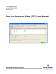
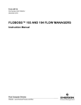
Flow Computer Division V-CONE METERING PROGRAM User Manual Form A6104 March 2002 V-Cone Metering Program User Manual Revision Tracking Sheet March 2002 This manual may be revised from time to time to incorporate new or updated information. The revision level of each page is indicated at the bottom of the page opposite of the page number. A change in revision level to any page also changes the date of the manual which appears on the front cover. Listed below is the revision level of each page that corresponds to the front cover date. Page All pages Revision 3 FloBoss and ROCLINK are marks of one of the Emerson Process Management companies. The Emerson logo is a trademark and service mark of Emerson Electric Co. All other marks are the property of their respective owners. Fisher Controls International, Inc. 2000-2002. All rights reserved. Printed in the U.S.A. While this information is presented in good faith and believed to be accurate, Fisher Controls does not guarantee satisfactory results from reliance upon such information. Nothing contained herein is to be construed as a warranty or guarantee, express or implied, regarding the performance, merchantability, fitness or any other matter with respect to the products, nor as a recommendation to use any product or process in conflict with any patent. Fisher Controls reserves the right, without notice, to alter or improve the designs or specifications of the products described herein. ii Rev 3 V-Cone Metering Program User Manual Table of Contents Page 1 Introduction ............................................................................................................................................ 1 2 Operation................................................................................................................................................ 2 2.1 V-Cone Flow Calculations ...................................................................................................... 2 3 Downloading the V-CONE Metering Program...................................................................................... 3 3.1 Program Download Requirements .......................................................................................... 3 3.2 Firmware Compatibility .......................................................................................................... 3 3.3 Program Download Procedure ................................................................................................ 3 4 V-CONE Metering Program Configuration........................................................................................... 7 4.1 V-Cone Outputs User Point .................................................................................................... 8 5 Flow History......................................................................................................................................... 12 Rev 3 iii V-Cone Metering Program User Manual [This page is intentionally left blank.] iv Rev 3 V-Cone Metering Program User Manual 1 INTRODUCTION The V-Cone Metering Program is designed for the ROC300-Series (with FlashPAC) and FloBoss 407 Remote Operations Controllers (ROCs). The program allows a Fisher ROC to calculate flow rates, integrate volumes, and historicalize values when the differential input (AI or MVS) for a gas flow calculation comes from a McCrometer V-Cone meter rather than an orifice plate. Gas compressibility calculations are implemented using Fisher firmware NX-19, AGA8-85, or AGA8-92 standards. The program is configured and downloaded to the ROC by using the ROCLINK Configuration Software (Version 2.20 or greater) or ROCLINK for Windows (Version 1.01 or greater). The program can be installed in ROC300-Series units with a FlashPAC. The program can also be installed into ROC407 FloBoss memory. The program runs at the same time with firmware AGA calculations for any flow in a given ROC, and allows V-cone configuration of any existent flow in a ROC. The fluids the program is designed for, and composition ranges, are natural gas and other related hydrocarbons as defined in NX-19 and AGA Report #8, 1985 and 1992 editions. The components of 00Q011 are: ♦ A McCrometer V-Cone Meter that outputs 1 analog differential pressure signal. ♦ Optional Fisher AI or/and MVS Modules. ♦ The V-Cone Metering user program that loads into ROC memory to provide support for the McCrometer V-Cone flow calculations. For a ROC312 the V-Cone Metering program allows up to 3 combinations of AGA and V-Cone flows to be configured and ran at a time, for a FloBoss 407 it allows up to 4 combinations of AGA and V-Cone flows, and for a ROC364 it allows up to 5 combinations of AGA and V-Cone flows to run at a time. This manual assumes that the user is familiar with the ROC and its configuration. For more information, refer to the ROCLINK Configuration Software User Manual. Rev 3 1 V-Cone Metering Program User Manual 2 OPERATION The ROC reads flow inputs (differential pressure, temperature, and static pressure) once every second, and at a user configured scan period performs an NX-19, AGA8-85 or AGA8-92 detail calculation, and a McCrometer V-Cone or AGA3 Instant Flow calculation, followed by volume integration. Each flow can be individually configured as AGA flow or V-Cone flow. For each flow the configuration is done through the AGA interface, and the calculated values are retrieved through both AGA interface and VCone User Point 29 for AGA flows, and through V-Cone User Point 29 for V-Cone flows. 2.1 V-Cone Flow Calculations The purpose of the V-Cone Flow calculation is to provide an instantaneous flow rate that is adjusted to contract pressure and temperature, as defined by the user through the AGA interface. The V-Cone calculations, equations and flowcharts are detailed in “Flow Calculations for the V-Cone Flowmeter” manual, ©2000, McCrometer Inc., Hemet, CA. 2 Rev 3 V-Cone Metering Program User Manual 3 DOWNLOADING THE V-CONE METERING PROGRAM NOTE: A PC-compatible computer must be connected to the ROC Operator Interface port before downloading is started, and RAM must be available in the intended download area. 3.1 Program Download Requirements The V-Cone Metering program is downloaded to, and then run from Flash and RAM memory in the ROC/FloBoss. The following information shows the requirements for downloading and running the software (00Q011): Program Vco3d8bc.h00 Vco2d0b4.h00 Vco2b064.h00 Vco3c874.h00 ROC Device ROC300-Series with Flashpac v.2.12 ROC300-Series with Flashpac v.2.12 ROC 407 FloBoss v.1.08 ROC 407 FloBoss v.1.08 Task Code at: Data at: UDPs USER 3 D800 BC00 29 USER 2 D000 B400 29 USER 2 USER 3 B000 C800 6400 7400 29 29 Figure 1. Program Versions All versions use 16KB memory for code (1 block) and 16kB memory for data (1 block). For information on viewing the memory allocation of user programs loaded in the ROC or FloBoss, refer to the ROCLINK Configuration Software User Manual. 3.2 Firmware Compatibility The V-Cone Metering Program is compatible ONLY with FlashPAC Version 2.12 and greater, and with FloBoss 407 version 1.08 and greater. 3.3 Program Download Procedure This section provides instructions for installing the V-Cone Metering Program into ROC/FloBoss memory. Make sure to read Section 3.1 of this manual for program and memory requirements. To download the V-Cone Program using ROCLINK: 1. Connect the ROC/FloBoss to your computer through the LOI port. 2. Logon to ROCLINK software. Rev 3 3 V-Cone Metering Program User Manual 3. Select Utilities from the ROCLINK menu bar. 4. Select User Programs. 5. Press the Download pushbutton. The Open File dialog box appears as shown in Figure 2. This display lists the names of all the files that have the .H00 extension and are located in the default Drive and Directory. Use the mouse or the Up Arrow (↑) and Down Arrow (↓) to select the desired file in the Files list. You may change the path or location using the Directory/Drive field. Figure 2. Open File Dialog Box 6. When the desired V-cone Program appears in the File Name field, press OK. 7. You may press the More Files pushbutton (see Figure 3) to select additional User Programs for installation. Press the Download pushbutton again to begin loading the V-cone Program. When the program has been downloaded, the following occurs: 4 • The program is automatically turned ON. • A Warm Start is automatically initiated. • The configurable data fields are located under the ROCLINK Meter - Meter Setup, Meter - Gas Quality, and User Data – V-Cone Outputs features. • A record is created in the Event Log. Rev 3 V-Cone Metering Program User Manual Figure 3. ROCLINK User Program Installation 8. To restart the program in the event the program becomes inactive such as after a cold start, select Flags from the System menu to display the ROC Flags screen similar to the screen shown in Figure 4. Figure 4. ROC Flags for a ROC 300-Series with a FlashPAC Rev 3 5 V-Cone Metering Program User Manual 9. Set the respective User Program flag to Active (Calc User Program is for all USER task programs). 10. Set the Write to EEPROM or Write to Internal Config Memory flag to Yes. This ensures that when a Cold Start is performed, the User Program automatically starts. 11. Press (F8)Save. Refer to the ROCLINK Configuration Software User Manual for additional information concerning User Programs. 6 Rev 3 V-Cone Metering Program User Manual 4 V-CONE METERING PROGRAM CONFIGURATION After the user program is loaded (see Section 3), the V-Cone program can be configured using the ROCLINK Configuration Software. The default AGA configuration is loaded into the ROC the first time the V-Cone Metering Program is installed and started. The configuration of a V-Cone meter run is accomplished through the standard ROCLINK meter run setup screens (general, advanced, gas quality, and history). The V-Cone specific configuration is configured through the V-Cone user-defined display for each meter run. NOTE: When configuring a meter run for V-Cone calculation, the meter type should be set to AGA3 in the standard meter setup. Rev 3 7 V-Cone Metering Program User Manual 4.1 V-Cone Outputs User Point V-Cone Outputs User Point displays calculated values for both AGA and V-Cone flows. It is accessed from the main ROCLINK screen under the “Data” menu, “User Data-V-Cone Outputs” item. Figure 5. V-Cone Outputs Data Access (00Q011 shown) 8 Rev 3 V-Cone Metering Program User Manual Figure 6. V-Cone Outputs Configuration Screen – ROCLINK for Windows Shown (00Q011 shown) General: - Selecting “Metric” or “US” changes the unit system. For each parameter the Fisher units are detailed for both cases. Point Tag – User Point Tag. Recommended to be different from AGA Points Tag in order to allow correct history logging, which is done on a tag basis. For instance, if AGA1 is the AGA tag, AGA_U1 might be used as the V-Cone outputs User point Tag. Instant Flow – Instant Flow, mcf/Day for US Units, or mm3/Day if Metric. Instant Energy – Instant Energy, mmbtu/Day for US Units, or GJ/Day if Metric. Flow Today – Volume accumulated today, mcf for US Units, or mm3 if Metric. Energy Today – Energy accumulated today, mmbtu for US Units, or GJ if Metric. Flow Yesterday – Volume accumulated the previous contract day, mcf for US Units, or mm3 if Metric. Energy Y’day – Energy accumulated the previous contract day, mmbtu for US Units, or GJ if Metric. Equivalent HWPF – hwpf for AGA flows, Equivalent hwpf for V-Cone Flows, always US units. V-Cone formula: Y * Sqrt ( DPpsf / DensFlow ), Y being the expansion factor. C Prime – C Prime for AGA flows, Equivalent C Prime for V-Cone Flows, always US units. Rev 3 9 V-Cone Metering Program User Manual V-Cone formula: Cacfs x 86.4 ( for Cacfs description see V-Cone documentation, 86.4 factor translates cft/sec to mcf/Day ) Sample Time – Sample time, seconds. Beta – Beta factor, diameter ratio for AGA flows, calculated with V-Cone formula for V-Cone flows. No units. Formulas: d/D - for AGA, both diameters at Tf Sqrt(1-d^2/D^2) – for V-Cone, both diameters at Tf Vel Approach – Velocity of approach factor. No units. Formula: 1 / sqrt ( 1 – Beta^4 ) Reynolds – Reynolds Number calculated with AGA formula for AGA and with V-Cone formula for VCone. No units. V-Cone Formula: Reynolds = 123.9 x velocity(ft/sec) x D at Tf (inches) x Density (lbm/cft) / viscosity ( cP ) Pressure Loss – Pressure Loss calculated with V-Cone formula for V-Cone flows, forced to 0.0 for AGA flows. % of Upstream Static Pressure Units. Expansion Factor – Expansion Factor calculated with AGA formula for AGA and with V-Cone formula for V-Cone. No units. V-Cone Formula: see V-Cone documentation. Velocity – Linear gas velocity with V-Cone formula for V-Cone flows, forced to 0.0 for AGA flows. Ft/sec for US Units, M/s for Metric Units. V-Cone Formula: Velocity = 4 x Qacfs(cft/sec) / ( Pi x D at Tf(ft) ^2 ), Qacfs being the uncorrected flow. Corr To Contract – Correction to contract conditions with V-Cone formula for V-Cone flows, forced to 0.0 for AGA flows. Always US Units. V-Cone Formula: ( PL / Pb ) x ( Tb / TL ) x ( Zb / ZL )- b index refers to contract while L index refers to flow/line conditions. Thermal Corr – Thermal correction for V-Cone calculated with V-Cone formula, forced to 0.0 for AGA flows. No units. Export To Soft Pt – Number of the soft point to which to export the previous calculated values. An export will be done each Scan Period, if configured to a valid soft point number (1 to 32). Needed for generic Fisher SCADA drivers which are not able to access User Points. Works for both AGA and V-Cone Flows. Enable V-Cone Calc – Non-zero value in this field enables the V-Cone calculation for the meter run. A 0 (zero) value allows standard AGA3/AGA7 calculation to execute for the meter run. 10 Rev 3 V-Cone Metering Program User Manual Correction Factor – Value of the correction factor in the McCrometer V-Cone meter. NOTE: C Prime and Equivalent HWPF are used for back calculation purposes, and are consistent with Fisher’s AGA implementation. Multiplying C Prime with HWPF one gets the uncorrected flow rate, and multiplying further with Corr To Contract the corrected flow rate for any archived period (minute, hour, day). For metric units the result is multiplied with a MCF to MM3 factor. Rev 3 11 V-Cone Metering Program User Manual 5 FLOW HISTORY For both AGA and V-Cone flows, history points 1 to 4 and 6 to 8 in flow history should be configured as follows: Hist Point 1 2 3 4 6 7 8 Point Type ERN (Extra Run Params) FLW (Flow Calcs) FLW (Flow Calcs) FLW (Flow Calcs) FLW (Flow Calcs) FLW (Flow Calcs) FLW (Flow Calcs) Parameter Minutes Today Current DP Current PF Current TF hwpf Instant Flow Instant Energ Archive Type Totalize Average Average Average Average Flow Accum Flow Accum For AGA flows and V-Cone flows (in ROC300-Series with FlashPAC version 2.20 or greater), history point 5 in flow history should be configured as follows: Hist Point 5 Point Type FLW (Flow Calcs) Parameter C Prime Archive Type Average For V-Cone flows (in ROC300-Series with FlashPAC version 2.12 or earlier or in FloBoss 407 version 1.08 or earlier), history point 5 in flow history should be configured as shown below. AGA reports capability will be available for AGA flows and for V-Cone flows with the exception of C prime value. Hist Point 5 Point Type U#29(User Pt.29) Parameter C Prime Archive Type Average Earlier versions of ROC300 FlashPAC and FB407 firmware will not allow disabling the C prime calculation by the standard AGA task. Archiving U#29 C prime parameter will save the correct value to ROC history, but the C prime value will not be pulled into AGA reports. If you have comments or questions regarding this manual, please direct them to your local sales representative or contact: Emerson Process Management Flow Computer Division Marshalltown, IA 50158 U.S.A Houston, TX 77065 U.S.A. Pickering, North Yorkshire UK Y018 7JA Website: www.EmersonProcess.com/flow 12 Rev 3