1
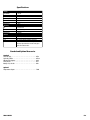
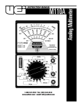
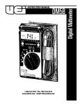
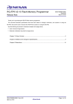
INSTRUCTION MANUAL
M75A
1-800-547-5740 • Fax: (503) 643-6322
www.ueitest.com • email: [email protected]
Introduction
The M75A has the features you need for testing electrical and HVAC/R
systems. Its voltage ranges are scaled to keep typical readings in the
middle of the scale for increased accuracy and resolution. It also
includes a low ohm scale to test critical connections as well as
microamps and millivolts functions to verify heat anticipator and flame
safeguard circuits.
Features include
• 17 ranges
• 1000 Volts AC and DC
• Resistance 50 kilohm
• DC micro/milli amps
• DC millivolt scale allows use of adapters
• Color-coded and mirrored scale plate
3. Mechanical Zero Adjust: Is a plastic screw located on the
meter face just beneath the green “FUSE PROTECTED OHM
CIRCUIT” label. This adjustment is used to set the pointer to the
zero index mark at the left side of the scale plate.
4. Input Jacks:
COM (-): The black test lead is used to connect this jack to the
negative, or common, side of the circuit under test.
VΩM (+): This adjustment is used to set the pointer to the zero
index mark at the left side of the scale plate.
Operating Instructions
WARNING!
Observe all safety precautions when measuring higher voltages.
Turn off power to the circuit under test. Set the M75A controls,
connect the test leads to the meter and then to the circuit under
test. Reapply power. If the pointer does not move, make sure that
the protective fuse is not open.
Safety Notes
Before using this meter, read all safety information carefully. In
this manual the word "WARNING" is used to indicate conditions
or actions that may pose physical hazards to the user. The word
"CAUTION" is used to indicate conditions or actions that may
damage this instrument.
Color Coding
The meter scale plate and front panel are color coded. The DC Voltages
and DC Current meter scale and “SELECTOR” switch positions are in
black. The OHMS meter scale and “SELECTOR” switch positions are in
green. The AC Voltage meter scales and “SELECTOR” switch positions
are in red.
Controls and Indicators
3
2
1
4
To provide an uncrowded easy-to-read meter scale plate a single meter
scale may be used for more than one position of the “SELECTOR”
switch. For example, the meter scale numerals 0 - 50 are used for the
following positions of the “SELECTOR” switch: 50V DC, 50µA DC, 50V
AC and 500V AC. To take a reading at any of the above “SELECTOR”
switch positions the 0 - 50 scale numerals are either read directly or
divided by 10. Example: (1) If the “SELECTOR” switch is set on 50V DC
then read the numerals directly. (2) If the “SELECTOR” switch is set on
500V AC then multiply the 0 - 50 numerals by 10 (this will give a scale
of 0 - 500).
Measuring DC Voltage
Set the “SELECTOR” switch to the appropriate range. Always start with
the 1000V DC position if unsure of the magnitude of voltage present.
Connect the black test lead to the “COM” jack and to the negative side
of the circuit under test. Connect the red test lead to the “+VΩM” jack
and to the positive side of the circuit under test. Read the voltage on the
black meter scale corresponding to the “SELECTOR” switch setting.
Note: the 250mV DC and the 50µA DC readings are taken at the same
position of the “SELECTOR” switch.
1. Selector Switch: Is used to select the circuit function and range.
it is good practice to start with the highest range setting of the
selector switch for a particular function if the magnitude of the
function is unknown.
2. ΩADJ: Is used only on the OHMS function. The purpose of this
control is to calibrate the M75A on the particular range selected
(Rx1, Rx10, etc.)
M75A-MAN
P. 1
Measuring DC Current
Set the “SELECTOR” switch to the appropriate range. Always start
with the 250 mA DC position if unsure of the magnitude of current
present. When taking current measurements the meter must be
connected in SERIES with the circuit, or circuit element, under test.
Break the connection at which current is to be measured. Place the
M75A in series with the circuit be connecting the black test lead to the
“COM” jack and to the lower voltage side of the circuit. Connect the
red test lead to the “+VΩM“ jack and to the higher voltage side of the
circuit. Read the current on the black meter scale corresponding to the
“SELECTOR” switch. The symbol “µ” is the standard symbol for the
word “MICRO”. Hence, 50 µA DC = 50 DC microamp.
Measuring Resistance
WARNING!
Remove all power to the circuit under test when making resistance
measurements. If any voltage is present in the test circuit an erroneous
reading will result and the 1/4A fuse may open.
Set the “SELECTOR” switch to the appropriate range. Connect one test
lead to the “COM” jack and the other test lead to the “+VΩM“ jack.
Touch the free ends of the test leads together. The pointer will swing to
the right hand side of thee scale. Adjust the “Ω ADJ“ control until the
pointer is set on the green numeral 0. (Note: If this adjustment cannot
be made refer to the “MAINTENANCE” section). Re-zero the M75A each
time the OHMS setting of the “SELECTOR” switch is changed. To make
the resistance measurement, connect the free ends of the test leads
across the element to be measured. The measured resistance value
will be the green numeral indicated on the OHMS scale times the
multiplier on the “SELECTOR” switch. For example, if the pointer is
on the numeral 4, and the “SELECTOR” switch is set on Rx 10, the
resistance is 40 ohms (4Ω x 10 = 40Ω).
Continuity tests are normally made to test a wire, or element, to see if it
is unbroken. Because continuity tests involve low values or resistance,
the “SELECTOR” switch should be set on the Rx1 position.
Testing Diodes / Transistors
A simple check of diode or transistor quality may be made with the
M75A. Using the same test procedure as for measuring resistance,
connect one test lead to one end of the diode and the other end of the
diode. Note the resistance reading. Then reverse the test leads and
again note the reading. If the two readings differ by a factor of ten then
the diode, (or transistor junction) is probably good. If the readings are
approximately the same then the diode is shorted. If a reading cannot
be obtained in either direction, the diode is probably open. Transistor
junction measurements should be taken between the base and emitter
leads, or between the base and collector leads.
Measuring AC Voltage
Set the “SELECTOR” switch to the appropriate range. Always start
with the 1000V AC position if unsure of the magnitude of voltage
present. Connect the test leads to the “COM” jack and the “VΩM“
jack and to the circuit under test. Read the voltage on the red meter
scale corresponding to the “SELECTOR” switch setting.
M75A-MAN
Maintenance
Periodic Service
WARNING!
Repair and service of this instrument is to be performed by qualified
personnel only. Improper repair or service could result in physical
degradation of the meter. This could alter the protection from
electrical shock and personal injury this meter provides to the
operator. Perform only those maintenance tasks that you are
qualified to do.
These guidelines will help you attain long and reliable service from
your meter:
• Calibrate your meter annually to ensure it meets original
performance specifications
• Keep your meter dry. If it gets wet, wipe dry immediately.
Liquids can degrade electronic circuits
• Whenever practical, keep the meter away from dust and
dirt that can cause premature wear
• Although your meter is built to withstand the rigors of daily
use, it can be damaged by severe impacts. Use reasonable
caution when using and storing the meter
Cleaning
Periodically clean your meter’s case using a damp cloth. DO NOT use
abrasive, flammable liquids, cleaning solvents, or strong detergents as
they may damage the finish, impair safety, or affect the reliability of the
structural components.
Battery Replacement
The purpose of the batteries is to supply power to the circuit under test
while making resistance measurements. Eventually the batteries will age
to the point where it will not be possible to zero the meter with the
“ΩADJ” control. When this happens the batteries should be replaced.
The two 1.5V size “AA” batteries are used only on the Rx1, Rx10, and
Rx100 setting of the “SELECTOR” switch and should be replaced as a
pair. Observe the proper battery polarity when replacing batteries. It is
recommended that all batteries be removed if the M75A is not to be
used for a long period of time. Remove the single screw in the rear of
the case for access to the batteries.
Fuses
The 1/4A, 2.0 ohm, fuse is in series with the “+VΩM“ input jack. If this
fuse is open none of the circuit functions will work. When replacing the
fuse be sure to replace it with a fuse of the same current rating and
internal resistance. The use of a fuse with a different internal resistance
may cause the accuracy of the OHMS scale to be off. Remove the single
screw in the rear of the case for access to the fuse.
Mechanical Zero Adjustment
The pointer is set to register 0 at the left hand edge of the scale when
there is no input to the M75 and it is laying face up on a flat surface. If
the pointer does not register 0, it may be reset to that position by carefully adjusting the plastic screw in the meter face, just below the green
“FUSE PROTECTED OHMS CIRCUIT” label.
P. 2
Specifications
Ranges
DC Millivolts
DC Volts
DC Microamps
DC Milliamps
OHMS
AC Volts
Temperature
Accuracy
DC
OHMS
AC
Temperature
General
Input Impedance
Batteries
Fuse
0 - 250 mV
0 - 2.5, 10, 50, 250, 1000 V
0 - 50 µA
0 - 25, 250 mA
0 - 500Ω, 5K, 50K
0 - 10, 50, 250, 500, 1000 V
0 - 250˚F
±3% of full scale
±3% of scale length
±4% of full scale
±2 divisions
20KΩ / V DC, 10KΩ / V AC
Two 1.5V, size AA (NEDA #15D) batteries
1/4A (2.0 ohm internal resistance) 3AG series
Note: To maintain calibration accuracy and instrument
protection, replacement fuse must be of the proper
current and resistance value.
Standard and Optional Accessories
Standard
Test leads (set) . . . . . . . . . . . . . . . . . . . . . . . . . . . . . . . . . . . . . . .ATL3
Test leads, rubber . . . . . . . . . . . . . . . . . . . . . . . . . . . . . . . . . . . . .ATL25
Alligator clip adapters . . . . . . . . . . . . . . . . . . . . . . . . . . . . . . . . . .AAC
Fuse 1/4A, 2Ω . . . . . . . . . . . . . . . . . . . . . . . . . . . . . . . . . . . . . . . .AF2
Battery 1.5V, size AA . . . . . . . . . . . . . . . . . . . . . . . . . . . . . . . . . . .AB1
Optional
Temperature adapter . . . . . . . . . . . . . . . . . . . . . . . . . . . . . . . . . .TA2K
M75A-MAN
P. 3
M75A
Analog Multimeter
Limited Warranty
The M75A is warranted to be free from defects in materials and workmanship for a period of
three years from the date of purchase. If within the warra n ty period your instrument should
become inoperative from such defects, the unit will be repaired or replaced at UEi’s option.
This warra n ty covers normal use and does not cover damage which occurs in shipment or
failure which results from alteration, tampering, accident, misuse, abuse, neglect or improper
maintenance. Batteries and consequential damage resulting from failed batteries are not
covered by warra n ty.
Any implied warranties, including but not limited to implied warranties of merchantability
and fitness for a particular purpose, are limited to the express warranty. UEi shall not be
liable for loss of use of the instrument or other incidental or consequential damages,
expenses, or economic loss, or for any claim or claims for such damage, expenses or
economic loss. A purchase receipt or other proof of original purchase date will be required
before warra n ty repairs will be rendered. Instruments out of warra n ty will be repaired (when
repairable) for a service charge. Return the unit postage paid and insured to:
1-800-547-5740 • FAX: (503) 643-6322
www.ueitest.com • Email: [email protected]
This warranty gives you specific legal rights. You may also have other rights which vary from
state to state.
PLEASE
RECYCLE
Copyright © 2007 UEi
M75A-MAN 1/07