1
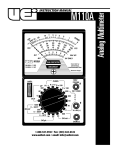
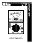
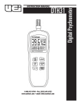
INSTRUCTION MANUAL
DM5B
1-800-547-5740 • Fax: (503) 643-6322
www.ueitest.com • email: [email protected]
Introduction
The DM5B digital multimeter is a pocket sized, hand held, battery
operated, voltage, current and continuity measurement instrument. It
provides the accuracy and numerous functions typically found in full
sized multimeters.
Features include
• 750 Volts AC & DC
• 5 Amps AC & DC
• Continuity
• Resistance to 30
• Megohms
• Autoranging
• Analog bar-graph
• Data hold
• Fuse protected current ranges
Safety Notes
Before using this meter, read all safety information carefully. In
this manual the word "WARNING" is used to indicate conditions
or actions that may pose physical hazards to the user. The word
"CAUTION" is used to indicate conditions or actions that may
damage this instrument.
• Always follow industry standard safety practices including protective
clothing, gloves and safety glasses when appropriate
• Do not attempt to measure any voltage that exceeds 1000 volts AC or
DC with this meter.
• Do not attempt to use this meter if either the meter or the test
leads have been damaged. Turn it in for repair at a qualified
repair facility
• Ensure meter leads are fully seated by making a quick continuity
check of the leads prior to making voltage measurements
• Keep your fingers away from the test lead’s metal probe
contacts when making measurements. Always grip the leads behind
the finger guards molded into the probes
• Use a current clamp adapter when measuring current that may
exceed 10 amps. See the accessories in UEi’s full-line catalog
• Do not open the meter to replace batteries or fuses while the
probes are connected
DM5B-MAN
WARNING!
Exceeding the specified limits of this meter is dangerous and can
expose the user to serious or possibly fatal injury.
• Always turn off power to a circuit (or assembly) under test
before cutting, unsoldering, or breaking the current path Even small amounts of current can be dangerous
• Always disconnect the live test lead before disconnecting the
common test lead from a circuit
• In the event of electrical shock, ALWAYS bring the victim to
the emergency room for evaluation, regardless of the victim’s
apparent recovery - Electrical shock can cause an unstable heart
rhythm that may need medical attention
• Higher voltages and currents require greater awareness of
physical safety hazards - Before connecting the test leads; turn
off power to the circuit under test; set the meter to the desired
function and range; connect the test leads to the meter first, then to
the circuit under test. Reapply power
• If any of the following indications occur during testing, turn off
the power source to the circuit under test:
• Arcing
• Flame
• Smoke
• Extreme Heat
• Smell of Burning Materials
• Discoloration or Melting of Components
CAUTION!
Do not attempt to remove the meter leads from the circuit under test. The
leads, the meter, or the circuit under test may have degraded to the point
that they no longer provide protection from the voltage and current
applied. If any of these erroneous re a d i n gs are observed, disconnect
power immediately and recheck all settings and connections.
International Symbols
P. 1
Operating Instructions
V:
Volts
Ω:
Ohms
: Resistor (schematic symbol)
:
Continuity mode (4.1 kilohertz tone)
:
Diode (schematic symbol)
mA:
Milliamps DC or AC
5A:
Five Amp DC or AC
Meter Lead Connections
WARNING!
Grip leads behind finger guards when making measurements.
The meter leads will be connected in this manner regardless of
the measurement:
Connect the black test lead to the terminal marked “COM” and
the red test lead to the terminal marked “V/mA/A/Ω”.
DC/AC Voltage Measurement
WARNING!
Electric shock, instrument damage, or equipment damage may result if
input voltages exceed 1000 Volts DC or AC RMS. Do not attempt to take
any unknown voltage measurement that may be in excess of 1000 Volts
DC or AC RMS.
1. Set the rotary switch to the “V” function (DC V or AC V). The
meter will default to the voltage source, press the “DC/AC”
push-button to switch to AC. The meter indicates which mode you
have selected at the far left of the display.
2. Touch the probes to the circuit under test and read the display.
NOTE: If the input voltage exceeds this meter’s range the indicator will
display the overload symbol “O.L.”. If a negative DC voltage is being
measured the “-” symbol will appear on the left side of the display.
Resistance Testing
Ensure your circuit is isolated from other circuit paths to prevent testing
the wrong path. The DM5B can measure up to 30 megohms.
1. Set the function switch to the resistance position “Ω/
“ and
note the overload symbol “O.L.” on the display. Megohms “MΩ”
is displayed in the lower right.
2. Touch the red lead to one side of the circuit (i.e. resistor) and the
black lead to the other side and read the display.
Continuity Testing
1. Set the function switch to the Continuity/Diode position “ / “.
The continuity symbol “ “ will be displayed in the upper left of
the display, the overload symbol “O.L.” in the center, and ohms
“Ω“ in the lower right.
2. Touch the red lead to one side of the circuit (i.e. wire) and the
black lead to the other side. If the circuit resistance is approximately
20 ohms or less a continuous tone will sound, indicating continuity.
Diode Testing
1. Set the function switch to the Continuity/Diode position “
/
“.
2. Press the “ / “ push-button immediately below and to the left
of the LCD. The diode symbol “ “ will be displayed in the lower
left of the display, the overload symbol “O.L. “ in the center, and
volts “V” in the upper right.
3. Isolate the diode from other circuit components, and connect the
red test lead to the diode, and the black to the other. A black band
is normally printed around the end of the cathode side of the
component. Note the displayed value.
4. Reverse the red and black test leads and again note the
displayed value.
If the reading in the first (forward biased) direction indicates some
measurable value and the reading in the reversed direction shows an
overload “O.L.” the diode is good. If the displayed value is low, or even
measurable, in both directions, the diode is probably shorted. If the
display indicated an overload “O.L.” in both directions, the diode is
probably open. Some diodes, however, require a higher biasing voltage
than this meter supplies. See UEi’s catalog to purchase an economical
high-power diode test lead adapter set if necessary.
Amperage Measurement
CAUTION!
The resistance, continuity and diode modes are protected to a maximum
of 500 volts. To avoid personal injury or damage to the instrument, do
not make measurements in these modes when open circuit voltage may
exceed 500 volts DC or AC.
WARNING!
The current functions are protected by a 150 volt rated fuse. To avoid
personal injury or damage to the instrument, do not measure current
sources having open circuit voltage greater than 250 volts DC or AC.
Current measurements are made in SERIES with the circuit (or circuit
element) under test. NEVER CONNECT THE TEST LEADS ACROSS A
VOLTAGE SOURCE when an amps measuring position is selected. This
can cause damage to the circuit under test or this meter.
DM5B-MAN
P. 2
To measure current, you must break the circuit under test (cut a wire
for example) and make the meter part of the circuit. This creates two
connection points. On one side is the power source and the other is the
load. If DC current is being measured, a minus sign will be displayed
when current is flowing opposite to the connection polarity.
1. Ensure power is off to the circuit to be tested.
2. Set the rotary switch to the mA or 5A position (depending on the
maximum possible amperage you will be measuring). The meter
will default to the DC current setting. If you have an AC current
source, press the “DC/AC” push-button to switch to AC. Th meter
i n d i cates which mode you have selected at the far left of the display.
3. Create a break in the circuit as described earlier and connect the
meter leads to the two points created at the break.
4. Apply power to the circuit and note your measurement value.
WARNING!
Do not remove the leads from the circuit until power is disconnected.
Battery and Fuse Replacement
When the battery icon appears in the upper right of the display, the
batteries must be replaced immediately. Low battery voltage can cause
incorrect readings and consequential damage.
1. To replace the batteries, remove the meter from its carrying case.
2. Slide the battery cover plate (on the back of meter) out.
3. Replace both batteries at once with type listed in the specifications.
4. Reassemble the meter.
Fuse Replacement
WARNING!
Replace fuses with the type listed in the specifications (also printed on
the circuit board) only.
1. To replace the fuses, remove the meter from its ca r rying case.
2. Slide the battery cover plate out (on the back of meter).
3. Remove the three back panel retaining screws and separate the
two halves.
Maintenance
Periodic Service
4. Locate and replace expended fuse.
• 5A near the bottom
• .5A near the middle
5. Reassemble the meter.
WARNING!
Repair and service of this instrument is to be performed by qualified
personnel only. Improper repair or service could result in physical
degradation of the meter. This could alter the protection from
electrical shock and personal injury this meter provides to the
operator. Perform only those maintenance tasks that you are
qualified to do.
These guidelines will help you attain long and reliable service from
your meter:
• Calibrate your meter annually to ensure it meets original
performance specifications
• Keep your meter dry. If it gets wet, wipe dry immediately Liquids can degrade electronic circuits
• Whenever practical, keep the meter away from dust and dirt
that can cause premature wear
• Although your meter is built to withstand the rigors of daily use,
it can be damaged by severe impactsUse reasonable caution
when using and storing the meter
Specifications
NOTE: Accuracy is stated as ± (% of reading + number of least
significant digits) at 32 to 104˚F, with relative humidity up to 80%.
Stated accuracy is valid for a period of one year after calibration. AC
conversions of this meter are average responding and calibrated to
the RMS value of a pure sine wave input.
DC Voltage
Range
Resolution
Accuracy
300 mV
0.1 mV
±(1.2% + 2 digits)
3V
.001 V
±(0.5% + 2 digits)
30 V
.01 V
±(1.2% + 2 digits)
300 V
.1 V
750 V
1V
±(1.5% + 3 digits)
Resolution
Accuracy
Protections
1000 V
AC Voltage
Cleaning
Periodically clean your meter’s case using a damp cloth. DO NOT use
abrasive, flammable liquids, cleaning solvents, or strong detergents as
they may damage the finish, impair safety, or affect the reliability of the
structural components.
Range
3V
.001 V
30 V
.01 V
300 V
.1 V
750 V
1V
Protections
±(2.0% + 3 digits)
1000 V
±(2.0% + 4 digits)
Clean the input terminals as follows:
1. Turn the meter off and remove all test leads.
2. Shake out any dirt that may be in the terminals.
3. Soak a new swab with alcohol and work the swab around in
each terminal.
DM5B-MAN
P. 3
DC Current
Range
Resolution
30 mA
.01 mA
300 mA
.1 mA
5A
.01 A
Accuracy
Protections
±(1.5% + 2 digits)
500 mA, 250 V
±(2.5% + 3 digits)
5 A, 250 V
AC Current
Range
Resolution
30 mA
10 mA
300 mA
100 mA
5A
Accuracy
Protections
±(2.0% + 4 digits)
500 mA, 250 V
10 A
±(3.0% + 4 digits)
5 A, 250 V
Range
Resolution
Accuracy
Protections
300
0.1
3K
1
30 K
10
±(1.2% + 3 digits)
500 V
300 K
100
3M
1K
30 M
10 K
Resistance
±(3.0% + 5 digits)
Diode Test
Resolution
Max Current
Max Voltage
Protection
0.8 mA
3.3 V
500 V
1 mV
Continuity
Frequency 4.1 K Hz tone when <20 Ω ± 10 Ω, Protected to 500 V
Feature Summary
Maximum voltage between any
750 V
terminal and earth ground
Digital display
3-3/4 digits, 3200 counts with automatic
polarity indication
Input impedance
10 Meg Ohms
Storage temperature
14˚ to 122˚F (-10˚ to 50˚C)
Operating temperature
32˚ to 104˚F (0˚ to 40˚C)
Battery type
Two 1.5 V L11554 Button Cell (GPATG) UEi # AB13
5 Amp fuse
250 V, 5 A, 5x15 mm (2AG) UEi # AF250
500 mA
250V, 0.5 A, 5x15 mm (2AG) UEi # AF251
DM5B-MAN
P. 4
DM5B
Digital Multimeter
Limited Warranty
The DM5B is warranted to be free from defects in materials and workmanship for a period of
one year from the date of purchase. If within the warra n ty period your instrument should
become inoperative from such defects, the unit will be repaired or replaced at UEi’s option.
This warra n ty covers normal use and does not cover damage which occurs in shipment or
failure which results from alteration, tampering, accident, misuse, abuse, neglect or improper
maintenance. Batteries and consequential damage resulting from failed batteries are not
covered by warra n ty.
Any implied warranties, including but not limited to implied warranties of merchantability
and fitness for a particular purpose, are limited to the express warranty. UEi shall not be
liable for loss of use of the instrument or other incidental or consequential damages,
expenses, or economic loss, or for any claim or claims for such damage, expenses or
economic loss. A purchase receipt or other proof of original purchase date will be required
before warra n ty repairs will be rendered. Instruments out of warra n ty will be repaired (when
repairable) for a service charge. Return the unit postage paid and insured to:
1-800-547-5740 • FAX: (503) 643-6322
www.ueitest.com • Email: [email protected]
This warranty gives you specific legal rights. You may also have other rights which vary from
state to state.
PLEASE
RECYCLE
Copyright © 2007 UEi
DM5B-MAN 1/07