1
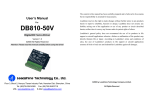
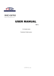
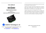
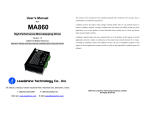
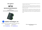
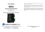
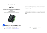
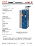
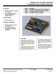
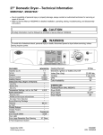
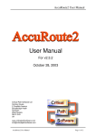
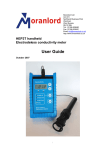
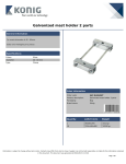
The content in this manual has been carefully prepared and is believed to be accurate, but no responsibility is assumed for inaccuracies. User’s Manual For DCS920 Analog DC Servo Driver Version 1.0 ©2009 All Rights Reserved Attention: Please read this manual carefully before using the driver! 3/F, Block 2, Nanyou Tianan Industrial Park, Nanshan Dist, Shenzhen, China Tel: (86)755-26434369 Fax: (86)755-26402718 URL: www.leadshine.com E-Mail: [email protected] Leadshine reserves the right to make changes without further notice to any products herein to improve reliability, function or design. Leadshine does not assume any liability arising out of the application or use of any product or circuit described herein; neither does it convey any license under its patent rights of others. Leadshine’s general policy does not recommend the use of its products in life support or aircraft applications wherein a failure or malfunction of the product may directly threaten life or injury. According to Leadshine’s terms and conditions of sales, the user of Leadshine’s products in life support or aircraft applications assumes all risks of such use and indemnifies Leadshine against all damages. ©2009 by Leadshine Technology Company Limited. All Rights Reserved DCS920 Brush DC Servo Drive Contents DCS920 Brush DC Servo Drive Table of Contents 1. Introduction ............................................................................................................. 1 2. Features ................................................................................................................... 1 3. Applications............................................................................................................. 1 4. Block Diagrams....................................................................................................... 2 5. Specifications .......................................................................................................... 2 6. Pin Assignment and Description ............................................................................. 4 7. Servo Setup ............................................................................................................. 7 7. Typical Connections and Settings ........................................................................... 9 7. Wiring Notes ......................................................................................................... 12 8. Order Information ................................................................................................. 13 APPENDIX ............................................................................................................... 14 1. Introduction The DCS920 PWM servo drive is designed to drive brush type DC motors at a high switching frequency. The drive can interface with digital controllers or be used stand-alone and requires only a single unregulated DC power supply. Input (Ref) gain, Tach Gain, Loop gain, Integrator Frequency and Offset can be adjusted using 26-turn potentiometers. The offset adjusting potentiometer can also be used as an on-board input signal for testing purposes. Furthermore, 3 red/green LEDs indicate operating status for faster setup. The drive is fully protected against over-voltage, under voltage, over-current, short-circuits from output to output, and over-temperature. Power Range Supply Voltage Peak Current Continuous Current 20 – 80 VDC 20A 10A 2. Features l High Performance and Cost-effective l 3 kHz bandwidth l Wide load inductance range: 0.2 - 40 mH l Flexibility! Internal 40-pin socket configures amp with no soldering l Separate and adjustable current Limits: Continuous, Peak and Peak-time l No integrator windup when disabled l Differential Input: ±10 V Analog l Current Monitor Output l 3 LED Indicators for Faster Setup: Normal/Enable, Power-OK, Fault (Short-circuits or over temperature) l Over/Under-voltage, over-current, short-circuits, over temperature protection l Surface Mount Technology Modes of Operation l Current l Tachometer Velocity l Voltage l IR Compensation 3. Applications l X-Y Stages l Robotics Tel: (86)755-26434369 I Web site: www.leadshine.com Tel: +086 0755-26434369 l Automated assembly machinery l Automatically guided vehicles 1 Web Site: www.leadshine.com DCS920 Brush DC Servo Drive DCS920 Brush DC Servo Drive Control Specifications 4. Block Diagrams Parameters Units Value Command Sources V Differential, 100K between inputs, 20V maximum Feedback Supported - Tachometer Modes of Operation - Current, Tachometer velocity, Voltage with IR compensation Motors Supported - Brushed, Voice coil Load Inductance mH Selectable with components on header socket: 200 µH to 40mH Current mode: 3kHz with 200µH load at maximum supply Bandwidth kHz voltage, varies with load inductance and RH20, CH18 values. Voltage-feedback mode: 200Hz max. - Hardware Protection Over voltage, Under voltage, Over current, Over temperature, Short circuit (Phase-Phase & Phase-Ground) Mechanical Specification Parameters Units Agency Approvals - Value CE Compliance to 89/336/EEC; Recognized Component to UL 508C Size (H*W*D) mm 83.3 x 129.3 x 36.3 Weight kg/lb 0.27 kg / 0.59 lb Storage Temperature Figure 1: Block diagram of the DCS920 ºC -20 - 65 Mechanical Specifications (unit:mm, 1 inch = 25.4 mm) 5. Specifications Power Specifications Parameters Supply Voltage Input Output Voltage Units VDC V Value 24 - 90 Vout = ±VDC*(0.97) - (Ro)*(Io) Over Voltage Limit VDC 92 Under Voltage Limit VDC 22 Peak Output Current A 20 A 10 kHz 25 Continuous Output Current Switching Frequency Tel: +086 0755-26434369 Ro=0.2 Figure 2: Mechanical specifications *Recommend use side mounting for better heat dissipation 2 Web Site: www.leadshine.com Tel: +086 0755-26434369 3 Web Site: www.leadshine.com DCS920 Brush DC Servo Drive DCS920 Brush DC Servo Drive Notes: TTL level (+5 V) inhibit/enable input. 1. Test conditions: 25°C ambient, Load = 200µH. in series with 1W. +VDC = 90VDC. 2. Lower inductance is acceptable for bus voltages well below maximum. Use external inductance to meet requirements. 3. Additional cooling and/or heatsink may be required to achieve rated performance. With S1 OFF, all Enable inputs must be grounded for the drive to operate. For operation with cards that output +5V to enable the 11 /ENABLE 1 +5V @ 5mA 2 GND 3 -5V @ -5mA ON. Delay on /Pos and /Neg enables is <1ms. Description I/O ±5 V @ 5 mA auxiliary power supply for customer use. Short circuit protected. Reference ground common with signal ground. 12 /POS ENAB 13 /NEG ENAB O GND O REF+ Maximum Input). Connect both Ref inputs to control card: Ref(+) I 14 +FAULT to card output, Ref(-) to card ground. Using both inputs will reject REF- twisted-pair cable to minimize noise pickup between drive and TACH- 7 (GND)TACH+ CURR MON Negative tachometer input (Maximum ±60 V). Use signal ground I Positive tachometer input and signal ground I current output. This pin has a maximum output of 6V when the drive outputs maximum peak current. Measure relative to signal R-C filter) pin has a maximum output of 6V when the drive outputs maximum peak current. Measure relative to signal ground. 6V @ O demands Ipeak 10 VOLT MON Tel: +086 0755-26434369 /RESET I disabled due to at least one of the following conditions: inhibit, output short circuit, over voltage, over temperature, power-up I Vout / 10, Bandwidth = 200 Hz 4 O Web Site: www.leadshine.com or until the /Reset input is grounded. For self-reset from such I conditions, wire /Reset to ground and the drive will reset every 50ms. 16 AUX O Measures the command signal to the internal current-loop. This CURR REF 15 for positive input. ground. 6V @ Ipeak (1kΩ, 33nF 9 /ENABLE. temperature will latch off the drive until power is cycled off & on, Current Monitor. Analog output signal proportional to the actual 8 Negative Direction Inhibit. See related description about I With the /RESET input open, output shorts or heatplate over I controller. 6 /ENABLE. reset. ground noise between control card and drive. Use shielded, 5 Positive Direction Inhibit. See related description about TTL level (+5V) output becomes high when power devices are Differential Reference Input (±10 V Operating Range, ±20 V 4 I Note: There is a 50ms delay /between Enable TRUE and drive P1 – Signal Connector Name grounding inputs will inhibit and +5V (or open) will enable. S1 flips polarity of all enable inputs. 6. Pin Assignment and Description Pin drive, turn S1 ON. Enable active level is now reversed so that Auxiliary analog input for test/offset. See block diagram please. I P2 – Power Connector Pin Name 1 MOTOR+ Positive Motor Output O 2 MOTOR- Negative Motor Output O 3 GND 4 GND 5 +VDC Tel: +086 0755-26434369 Description I/O Power Ground (Common with signal ground) DC Power Input GND GND I 5 Web Site: www.leadshine.com DCS920 Brush DC Servo Drive Switch Functions: S1: ENAB LO/HI S2: Integrator ON/OFF S1 OFF: Ground enables, open or +5V inhibits (/Enable, /Pos & /Neg enable) S1 ON : Open or +5V enables, ground inhibits (/Enable, /Pos & /Neg enable) S2 ON: Torque mode ( integrator off, flat-gain ), OFF: velocity mode ( integrator on, tachometer mode ) Potentiometer Functions: REF GAIN TACH GAIN LOOP GAIN INTEG FREQ OFFSET/TEST Attenuates Ref input from x1 to 0; controls overall amplifier gain ( amps / volt, rpm / volt, or volts / volt ) Tach feedback gain: sets basic rpm / volt ratio; also used as IR comp feedback control Servo preamp DC gain: increases amps / volt gain in torque mode; controls bandwidth in velocity mode Integrator frequency control: not used in torque mode/; controls stiffness and speed stability in velocity mode DCS920 Brush DC Servo Drive 7. Servo Setup Setup Sequence 1) Set RH15, RH16, and RH17 for motor current-limits to protect motor during setup. Disconnect motor and monitor CURR Ref signal at P1-9 while making settings. 2) Set CH18, RH20 on header for armature inductance. 3) Connect enable inputs. Set S1 for your enable signal polarity. 4) Connect motor and (if used ) tachometer. 5) Connect drive to transformer-isolated DC power supply. 6) Adjust pots and switch S2 according to operating mode. Component Header Use to set output current or rpm to zero. RH9 = 10 M for OFFSET function, RH9 = 100k for Test function Logic Inputs: Input voltage range Logic threshold voltage ( LO to HI transition ) Input resistance 0 to +24V 2.5V ( Schmitt trigger inputs with hysteresis ) 10K pull-up to +5V, R-C filters to internal logic Logic Outputs: +Fault ( /Normal ) HI = Overtemp OR output short OR power NOT-OK, OR NOT-Enabled; LO = Operating normally AND enabled; HI output voltage LO output voltage 2.4V min at -5.2 mA max., +5V maximum 0.5V max at 5.2 mA max. Figure 3: Component header Armature Inductance (CH18 & RH20): Indicators (LED’s): Normal Green: ON = Drive Enabled AND Normal ( power OK, no output shorts, no overtemp ) Power OK Fault Green: ON = Power OK ( +VDC >22V AND ( +VDC <92V) Red: ON = Output short-circuit or over-temperature condition Tel: +086 0755-26434369 6 Web Site: www.leadshine.com Load (mH) 0.2 - 0.5 2 - 5.9 6 - 19 20 - 40 0.6 - 0.9 Component CH18 (nF) 4.7 4.7 4.7 4.7 4.7 RH20 (kΩ) 10 49.9 150 330 470 Note: Values in bold & italics are factory installed standard. Values shown are for 90V. At lower supply voltages RH20 may be increased and CH18 decreased. To customize values: short CH18, Tel: +086 0755-26434369 7 Web Site: www.leadshine.com DCS920 Brush DC Servo Drive select RH20 for best step response in current-mode, next select CH18 for lowest value that does not degrade step response. Values from table work well for most applications. To optimize compensation with custom values: 1) Turn S2 ON. Disconnect tachometer if used. Set REF GAIN pot fully CW, Loop Gain pot fully CCW. 2) Replace CH18 with a jumper (short). 3) Apply 20Hz square wave input to Vref. Adjust for ±0.25V at CURR Mon (P1-8). 4) Choose value for RH20 that gives best step response without oscillation. 5) Replace CH18 with 4.7nF. 6) If waveform shows >10% overshoot, try larger capacitor until overshoot is 10% or less. If no change is seen, try smaller value for CH18 until overshoot appears. Peak Current Limit (RH15): DCS920 Brush DC Servo Drive Peak Current Limit (s) 1 0.8 0.6 0.4 0.2 RH17 (MΩ) open 10 2.2 1 330 Note: Values in bold & italics are factory installed standard. Peak times double after polarity reversal. 7. Typical Connections and Settings A complete servo system should include servo motor, servo driver, power supply, controller and feedback device. Typical connections of three operation modes are shown as the following Figure4 to figure6. Current (Torque) Mode Drives are shipped with no part installed in RH15. This delivers the drives peak rated current. For lower settings use values from the table. Peak Current Limit (%) 100 80 60 40 20 RH15 (kΩ) open 68 33 15 6.2 Note: Values in bold & italics are factory installed standard. Peak current limit should be set greater than continuous current limit. If Ipeak < Icont then peak overrides continuous limit and Icont = Ipeak. Minimum setting for peak current is 0% Minimum setting for continuous current is 16%.with RH16 = 0 W. Continuous Current Limit (RH16): Choose RH16 based on the motor manufacturers specification for your motor. Table values give basic settings. This setting keeps the motor within its thermal limits. Note that this limit measures average current and will not work on symmetrical waveforms such as might occur during system oscillation. Use an external thermal circuit breaker for protection from such over-current faults. Continuous Current Limit (%) 100 80 60 40 20 RH16 (kΩ) open 100 39 15 1 Note: Values in bold & italics are factory installed standard. Continuous current sense is for average current. Symmetrical waveforms with zero average value may cause over-temperature shutdown of drive or motor damage due to high I2R losses. Peak Current Time-Limit (RH17): Header component RH17 controls the length of time for which the drive will output peak current. When peak currents that are less than the drives peak rated current, this time will increase, eventually becoming infinite as you reach the continuous current. After a polarity reversal, the peak time will be twice that of a unipolar current change. Tel: +086 0755-26434369 8 Web Site: www.leadshine.com Figure 4: Typical connection of torque mode For transconductance: ( Iout / Vref ) = Ipeak / 10V 1) Set S2 ON. 2) Set Ref Gain fully CW. 3) Set Loop Gain fully CCW. 4) To increase gain, turn Loop Gain CW. To decrease gain, turn Ref Gain CCW. Tel: +086 0755-26434369 9 Web Site: www.leadshine.com DCS920 Brush DC Servo Drive Velocity Mode with Brush Tachometer DCS920 Brush DC Servo Drive Voltage Feedback & IR Comp In voltage mode, the voltage that is output to the motor is fed back to close a voltage loop. Since the voltage across the motor is proportional to the speed of the motor, this will allow coarse control of the motor speed, suitable for AGV’s, conveyors, or a Mars Lander. Operation will be much like a tachometer. Figure 5: Typical connection of velocity mode Disconnect motor from machinery during setup! Tachometer reversal will cause uncontrolled run-away! Set Tach Gain, Loop Gain and Integ. Freq. pots fully CCW. 1) Set S2 ON. Connect motor and tach and DC power, enable drive and spin shaft. If motor runs away, reverse tachometer connections. 2) Apply 5Hz square wave to Ref inputs. Adjust for ±0.25V at Tach input ( P1-6 ). 3) Adjust Loop Gain pot CW until oscillation begins, then back-off 2 turns. If oscillation cannot be eliminated, reduce RH12 until adjustment is possible. 4) Set S2 OFF. Turn Integ Freq CW until overshoot exceeds 10%, or oscillation begins. Back off for best step response. If overshoot is excessive with pot CCW, change CH2 to 0.47mF and retry. Use value of CH2 that gives good adjustment range for Integ Freq pot. 5) Adjust Tach Gain pot for desired Vtach / Vref ratio. Repeat steps 2-4. Ref Gain pot will reduce Vtach / Vref ratio without affecting tuning. If oscillation occurs when motor is connected to load, repeat steps 2-4. Figure 6: Typical connection of voltage feedback with IR comp Voltage mode with no IR comp Procedure Determine the voltage gain required. Example: If 24V output is required with 10V input then, Gain = Output Voltage / Input Voltage = 24V/10V = 2.4 Use the table for RH10 if the gain is common or use the formula to calculate uncommon gains. Install the resistor in the amplifier header Position RH10. Gain RH10 (kΩ) 1.2 12 2.4 24 7.5 75 15 150 Use exact or next larger value. (RH3 must be factory default 100K Ohms) See functional diagram. Set S2 OFF, Ref Gain, Integ Freq & Tach Gain pots fully CW, Loop Gain pot fully CCW. Connect oscilloscope to P1-10, Output Voltage monitor. Apply ±1V, 10Hz square wave to Ref inputs. Check for oscillation. If oscillation occurs, decrease RH12 to 10kΩ. Oscillation should now be gone. Tel: +086 0755-26434369 10 Web Site: www.leadshine.com Tel: +086 0755-26434369 11 Web Site: www.leadshine.com DCS920 Brush DC Servo Drive The Loop Gain and Integration Gain can be adjusted to effect the step response. Critical damping is recommended. See the Step Response diagram. DCS920 Brush DC Servo Drive 3. For best noise immunity, use twisted shielded pair cable for reference and tachometer inputs. 4. For EMI reduction and CE compliance, use shielded cable for motor and DC power. Grounding & Power Supplies Connect positive terminal of power supply to P2-5, negative terminal to P2-4. For best results do not ground power supply, but ground each drive with heavy wire from P2-3 to equipment ‘star’ ground point. If power supply is >1m from drives, add local filter capacitor near drives (250µF minimum per drive). Figure 7: Step response Note: If the motor has a large resistance, refer to the following section for the IR compensation procedure. However, for most motors with low motor resistance and a normal back-EMF range, no IR compensation will be required. 8. Order Information DCS920 20A peak, 10A continuous, 24-90 VDC brush motor drive Example: Motor resistance R = 0.5 Ohm, Back-Emf constant Ke = 10V/krpm Note: What is the speed lost at 3000rpm if 5Amps of current is continuously delivered? 1. For “no-pots” or custom component configurations, contact Leadshine [email protected]. Answer: 5Amps * 0.5ohms = 2.5V / 10V/krpm = 0.25krpm or 250rpm loss of speed, not bad regulation. Voltage mode with IR comp Voltage mode with no IR comp is used with position loops that have no “D” term, or that output a position error signal only. IR comp is used mostly with open-loop speed control systems. Procedure 1) (Skip this step if no IR comp.) Jumper P1-6 to P1-8. Tach Gain pot now functions as IR comp adjustment (full CW = no IR comp). 2) Select RH10. Use exact or next larger value. 3) Set S2 OFF, Ref Gain, Integ Freq & Tach Gain pots fully CW, Loop Gain pot fully CCW. 4) Connect oscilloscope to P1-10, Output Voltage monitor. 7. Wiring Notes IMPORTANT! ALWAYS REMOVE POWER WHEN CHANGING HEADER PARTS!! 1. All drive grounds are common (P2-3,4 & P1-2,7) Case is isolated from drive circuits. 2. For ground-active enable inputs, set S1 OFF For +5V active enables, set S2 ON (open inputs will enable drive via internal pullups to +5V). Tel: +086 0755-26434369 12 Web Site: www.leadshine.com Tel: +086 0755-26434369 13 Web Site: www.leadshine.com DCS920 Brush DC Servo Drive DCS920 Brush DC Servo Drive SHIPPING FAILED PRODUCT APPENDIX TWELVE MONTH LIMITED WARRANTY Leadshine Technology Co., Ltd. warrants its products against defects in materials and workmanship for a period of 12 months from shipping date. During the warranty period, Leadshine will either, at its option, repair or replace products which proved to be defective. If your product should fail during the warranty period, e-mail customer service at [email protected] to obtain a returned material authorization number (RMA) before returning product for service. Please include a written description of the problem along with contact name and address. Send failed product to distributor in your area or: Leadshine Technology Co., Ltd. Floor 3, Block 2, Tianan Industrial Park, Nanshan Dist, Shenzhen, China. Also enclose information regarding the circumstances prior to product failure. EXCLUSIONS The above warranty shall not apply to defects resulting from: improper or inadequate handling by customer; improper or inadequate customer wiring; unauthorized modification or misuse; or operation beyond the electrical specifications of the product and/or operation beyond environmental specifications for the product. OBTAINING WARRANTY SERVICE To obtain warranty service, a returned material authorization number (RMA) must be obtained from customer service at e-mail: [email protected] before returning product for service. Customer shall prepay shipping charges for products returned to Leadshine for warranty service, and Leadshine shall pay for return of products to customer. WARRANTY LIMITATIONS Leadshine makes no other warranty, either expressed or implied, with respect to the product. Leadshine specifically disclaims the implied warranties of merchantability and fitness for a particular purpose. Some jurisdictions do not allow limitations on how long and implied warranty lasts, so the above limitation or exclusion may not apply to you. However, any implied warranty of merchantability or fitness is limited to the 12-month duration of this written warranty. Tel: (86)755-26434369 14 Web site: www.leadshine.com Tel: +086 0755-26434369 15 Web Site: www.leadshine.com