1
Trux Configuration
Guide
Tx700 / Tx800
User Manual Tx800
Notice:
LXE Inc. reserves the right to make improvements or changes in the products described in this manual at any time
without notice. While reasonable efforts have been made in the preparation of this document to assure its accuracy,
LXE assumes no liability resulting from any errors or omissions in this document, or from the use of the
information contained herein. Further, LXE Incorporated, reserves the right to revise this publication and to make
changes to it from time to time without any obligation to notify any person or organization of such revision or
changes.
Copyright Notice:
This manual is copyrighted. All rights are reserved. This document may not, in whole or in part, be copied,
photocopied, reproduced, translated or reduced to any electronic medium or machine-readable form without prior
consent, in writing, from LXE Inc.
Copyright © 2009 by LXE Inc. An EMS Technologies Company.
125 Technology Parkway, Norcross, GA 30092 U.S.A. (770) 447-4224
Trademarks:
LXE® and Spire® are registered trademarks of LXE Inc. RFTerm® is a registered trademark of EMS Technologies,
Norcross, GA.
Microsoft, Windows and the Windows logo are registered trademarks of Microsoft Corporation in the United States and/or
other countries.
RAM® and RAM Mount™ are both trademarks of National Products Inc., 1205 S. Orr Street, Seattle, WA 98108.
Intel and Pentium are trademarks or registered trademarks of Intel Corporation or its subsidiaries in the United States and other
countries.
WLinq is a trademark of FreeFloat, AB. Information in Appendix C, “FreeFloat WLinq”, is copyright 1998-2007 FreeFloat
AB and is used with permission from FreeFloat AB.
The Bluetooth® word mark and logos are owned by the Bluetooth SIG, Inc. and any use of such marks by LXE, Inc. is under
license.
All other brand or product names are trademarks or registered trademarks of their respective companies or organizations.
When this manual is in PDF format: “Acrobat® Reader® Copyright © 2009 Adobe Systems Incorporated. All rights reserved.
Adobe®, the Adobe logo, Acrobat®, and the Acrobat logo are registered trademarks of Adobe Systems Incorporated.” applies.
Revision Notice
Revision
Section
Explanation
C
3.4.1 Configuration
Added reference to FreeFloat WLinq documentation.
C
5.2 Custom OS Installation
Revised section.
B
2 Installation
Added new section “Install Mounting Brackets”.
B
4.2 Bluetooth
Added new section “LXE 8652 Bluetooth Ring Scanner”.
C
Notices and copyrights
Updated for 2009.
C
6. FreeFloat WLinq
Added new section.
Revision A, Initial Release, October 2008
Revision B, January 2009
Revision C, February 2009
2
E-EQ-TRUXCONFIG-C
Table of Contents
1
INTRODUCTION AND INSTALLATION
9
1.1
Who should read this manual ......................................................................... 9
1.2
Notices .............................................................................................................. 9
1.3
General Information ......................................................................................... 9
1.4 How to use this manual ................................................................................. 10
1.4.1
Symbols used............................................................................................................10
2
INSTALLATION
2.1
11
Personal safety............................................................................................... 11
2.2 Product safety ................................................................................................ 11
2.2.1
Supplying power ......................................................................................................11
2.2.2
Humidity, moisture, cold and heat ...........................................................................11
2.2.3
Interference...............................................................................................................11
2.2.4
Vibrations .................................................................................................................11
2.3 Typical usage.................................................................................................. 11
2.4 Connections and adapters ............................................................................ 12
2.4.1
Interfaces and connections, Tx800...........................................................................12
2.4.1.1
Under the Tx800 service-lid.............................................................................................. 13
2.4.2
Interfaces and connections, Tx700...........................................................................14
2.4.3
Peripherals and accessories ......................................................................................15
2.5 Electrical installation ..................................................................................... 16
2.5.1
Connecting to power source .....................................................................................16
2.5.2
Connecting electrical cables to power sources.........................................................16
2.5.2.1
2.5.2.2
2.6
DC to DC Converter.......................................................................................................... 19
DC to DC Converter with Blackout Screen Box............................................................... 20
Mounting the Tx800 port lid........................................................................... 21
2.7 Best practice recommendations ................................................................... 21
2.7.1
Ergonomics...............................................................................................................21
2.7.2
Cable Protection .......................................................................................................21
2.7.3
Conductors, Terminals and Strain Relief .................................................................22
2.7.4
Bundle Band (UV- and Oil resistant) .......................................................................22
2.7.5
Conduit Entries and Cable Ports ..............................................................................22
2.7.6
DC/DC Placement and Mounting ............................................................................22
2.7.7
DC/DC Electrical Installation ..................................................................................23
2.7.8
Power Cables to Printers and Scanners ....................................................................23
2.8 Install Mounting Brackets.............................................................................. 24
E-EQ-TRUXCONFIG-D-ARC
3
Table of Contents
2.8.1
2.8.2
2.8.2.1
2.8.2.2
2.8.2.3
2.8.2.4
User Manual Tx800
RAM Mount System ................................................................................................24
Mounting Procedure.................................................................................................25
Step 1 – Mount Vehicle RAM Ball(s)............................................................................... 25
Step 2 – Prepare Tx700 or Tx800 ..................................................................................... 26
Step 3 – Attach Keyboard to Bracket................................................................................ 28
Step 4 – Attach Tx700 or Tx800 and Keyboard Assembly to RAM Base........................ 29
2.8.3
Completed Assembly ...............................................................................................29
2.9 Installation of peripherals.............................................................................. 30
2.9.1
Supplying power to peripherals................................................................................30
3
SYSTEM CONFIGURATION
31
3.1
Introduction .................................................................................................... 31
3.2
Soft Keyboards............................................................................................... 31
3.3 Trux Manager.................................................................................................. 32
3.3.1
Trux Manager for Tx700..........................................................................................32
3.3.1.1
3.3.1.2
3.3.1.3
3.3.1.4
3.3.1.5
3.3.2
3.3.2.1
3.3.2.2
3.3.2.3
3.3.2.4
3.3.2.5
Main Tab ........................................................................................................................... 32
General Settings Tab ......................................................................................................... 33
UPS Tab ............................................................................................................................ 35
Display Backlight Tab....................................................................................................... 36
Advanced Tab ................................................................................................................... 37
Trux Manager for Tx800..........................................................................................38
Main Tab ........................................................................................................................... 38
General Settings Tab ......................................................................................................... 39
UPS Tab ............................................................................................................................ 41
Display Backlight Tab....................................................................................................... 42
Advanced Tab ................................................................................................................... 43
3.4 Wedge.............................................................................................................. 44
3.4.1
Configuration ...........................................................................................................44
3.5 Touchscreen ................................................................................................... 45
3.5.1
Using the stylus to select screen objects ..................................................................45
3.5.2
Calibrating the touchscreen ......................................................................................45
4
WIRELESS NETWORK CONFIGURATION
47
4.1 802.11 Radio ................................................................................................... 47
4.1.1
802.11b/g Radio .......................................................................................................47
4.1.1.1
4.1.1.2
4.1.1.3
4.1.1.4
4.1.1.5
4.1.1.6
4.1.1.7
4.1.1.8
4
Wireless Zero Config ........................................................................................................ 47
Using the BWU ................................................................................................................. 48
No Security........................................................................................................................ 48
WEP .................................................................................................................................. 49
LEAP................................................................................................................................. 50
WPA-PSK ......................................................................................................................... 51
PEAP/MS-CHAP .............................................................................................................. 52
PEAP-GTC........................................................................................................................ 53
E-EQ-TRUXCONFIG-D-ARC
User Manual Tx800
Table of Contents
4.1.1.9 EAP-TLS........................................................................................................................... 54
4.1.1.10 WPA LEAP..................................................................................................................... 56
4.1.1.11 EAP-FAST ...................................................................................................................... 57
4.1.2
4.1.2.1
4.1.2.2
4.1.2.3
4.1.2.4
4.1.2.5
4.1.2.6
4.1.2.7
4.1.2.8
4.1.2.9
4.1.2.10
4.1.2.11
802.11a/b/g Radio ....................................................................................................58
Wireless Zero Config ........................................................................................................ 58
Using the ACU.................................................................................................................. 59
No Security........................................................................................................................ 60
WEP .................................................................................................................................. 61
LEAP................................................................................................................................. 63
WPA-PSK ......................................................................................................................... 65
PEAP/MS-CHAP .............................................................................................................. 66
PEAP-GTC........................................................................................................................ 68
EAP-TLS........................................................................................................................... 70
WPA LEAP..................................................................................................................... 72
EAP-FAST ...................................................................................................................... 74
4.1.3
Certificates ...............................................................................................................77
4.2 Bluetooth......................................................................................................... 78
4.2.1
Devices Tab..............................................................................................................78
4.2.2
Options Tab ..............................................................................................................80
4.2.3
COM Ports Tab ........................................................................................................81
4.2.4
Hardware Tab...........................................................................................................82
4.2.5
LXE 8652 Bluetooth Ring Scanner..........................................................................82
4.3 WAN................................................................................................................. 83
4.3.1
Overview ..................................................................................................................83
4.3.2
Requirements............................................................................................................83
4.3.3
SIM card installation ................................................................................................83
5
OPERATING SYSTEM
87
5.1 System Recovery ........................................................................................... 87
5.1.1
Recovery Media .......................................................................................................87
5.1.2
Recovery Process .....................................................................................................87
5.1.2.1
5.1.2.2
5.2
6
Startup ............................................................................................................................... 88
Wizard walk-through ........................................................................................................ 88
Custom OS Installations ................................................................................ 89
FREEFLOAT WLINQ
E-EQ-TRUXCONFIG-D-ARC
91
5
Table of Contents
User Manual Tx800
Illustrations
Figure 1 Overview connections and interfaces, Tx800.....................................................................................12
Figure 2 Overview: connections and interfaces under the service-lid ..............................................................13
Figure 3 Overview connections and interfaces, Tx700.....................................................................................14
Figure 4 Connection for power supply .............................................................................................................16
Figure 5 Wiring Diagram, Without Blackout Screen Box ................................................................................19
Figure 6 Wiring Diagram, With Blackout Screen Box .....................................................................................20
Figure 7 Sample RAM Ball Mounting Options ................................................................................................25
Figure 8 Screw Installation, Tx700 or Tx800 ...................................................................................................26
Figure 9 Attach Keyboard to Mounting Plate ...................................................................................................28
Figure 10 Completed RAM Mount Assembly ..................................................................................................29
Figure 11 Sample Soft Keyboard......................................................................................................................31
Figure 12 Tx700 Trux Manager Main Tab .......................................................................................................32
Figure 13 Tx700 Trux Manager General Settings Tab .....................................................................................33
Figure 14 Tx700 Trux Manger UPS Tab ..........................................................................................................35
Figure 15 Tx700 Trux Manager Display Backlight Tab...................................................................................36
Figure 16 Tx700 Trux Manager Advanced Tab ...............................................................................................37
Figure 17 Tx800 Trux Manager Main Tab .......................................................................................................38
Figure 18 Tx800 Trux Manager General Settings Tab .....................................................................................39
Figure 19 Tx800 Trux Manger UPS Tab ..........................................................................................................41
Figure 20 Tx800 Trux Manager Display Backlight Tab...................................................................................42
Figure 21 Tx800 Trux Manager Advanced Tab ...............................................................................................43
Figure 22 WLinq Communication tab ..............................................................................................................44
Figure 23 WLinq Data Editing Tab ..................................................................................................................44
Figure 24 BWU, No Security............................................................................................................................48
Figure 25 BWU, WEP ......................................................................................................................................49
Figure 26 BWU, LEAP.....................................................................................................................................50
Figure 27 BWU, WPA-PSK .............................................................................................................................51
Figure 28 BWU, PEAP/MS-CHAP ..................................................................................................................52
Figure 29 BWU, PEAP-GTC............................................................................................................................53
Figure 30 BWU, EAP-TLS Client Identity.......................................................................................................54
Figure 31 BWU, EAP-TLS Server Identity ......................................................................................................55
Figure 32 BWU, WPA LEAP...........................................................................................................................56
Figure 33 BWU, EAP-FAST ............................................................................................................................57
Figure 34 ACU, General Tab............................................................................................................................59
Figure 35 ACU, No Security ............................................................................................................................60
Figure 36 ACU, WEP .......................................................................................................................................61
Figure 37 ACU, WEP Key................................................................................................................................62
Figure 38 ACU, LEAP......................................................................................................................................63
Figure 39 ACU, LEAP Credentials...................................................................................................................64
Figure 40 ACU, WPA-PSK ..............................................................................................................................65
Figure 41 ACU, Preshared Key ........................................................................................................................65
Figure 42 ACU, PEAP/MS-CHAP ...................................................................................................................66
Figure 43 ACU, PEAP/MS-CHAP Credentials ................................................................................................67
Figure 44 ACU, PEAP-GTC.............................................................................................................................68
Figure 45 ACU, PEAP-GTC Credentials .........................................................................................................69
Figure 46 ACU, EAP-TLS................................................................................................................................70
Figure 47 ACU, EAP-TLS Credentials.............................................................................................................71
Figure 48 ACU, WPA LEAP............................................................................................................................72
Figure 49 ACU, WPA LEAP Credentials.........................................................................................................73
Figure 50 ACU, EAP-FAST .............................................................................................................................74
Figure 51 ACU, EAP-FAST Authentication ....................................................................................................75
Figure 52 ACU, EAP-FAST Credentials ..........................................................................................................76
6
E-EQ-TRUXCONFIG-D-ARC
User Manual Tx800
Figure 53
Figure 54
Figure 55
Figure 56
Figure 57
Figure 58
Figure 59
Figure 60
Figure 61
Figure 62
Figure 63
Figure 64
Figure 65
Figure 66
Figure 67
Table of Contents
Install Certificate Chain....................................................................................................................77
Request Certificate ...........................................................................................................................77
Bluetooth Devices Tab .....................................................................................................................78
Add Bluetooth Device Wizard .........................................................................................................79
Discovered Bluetooth Devices .........................................................................................................79
Bluetooth Options Tab .....................................................................................................................80
Bluetooth COM Ports Tab................................................................................................................81
Bluetooth Hardware Tab ..................................................................................................................82
Open the Trux Computer..................................................................................................................83
PC Card Eject Button .......................................................................................................................84
Install SIM Card ...............................................................................................................................84
PIN Code Prompt .............................................................................................................................84
WAN System Tray Icon ...................................................................................................................85
WAN Network Configuration ..........................................................................................................85
WAN Disconnect..............................................................................................................................85
E-EQ-TRUXCONFIG-D-ARC
7
Table of Contents
8
User Manual Tx800
E-EQ-TRUXCONFIG-D-ARC
1 Introduction and Installation
This manual covers the mounting and configuration of the Tx700 and Tx800 computers.
1.1
Who should read this manual
Use this manual if you are responsible for installing and configuring, Trux Solutions. It is assumed the
reader of this document is familiar with Microsoft Windows operating systems. Manuals directed to the
general user are:
1.2
•
Tx700 User’s Guide
•
Tx800 User’s Guide.
Notices
This manual describes the physical mounting and system administration functions for the Trux computer.
1.3
General Information
Like any personal computer, there are many aspects to the setup and configuration of the Trux Tx700 or
Tx800. Much of the setup and configuration of the Truux computer is dependent upon the optional features
(both hardware and software) installed on the computer. Since the Trux computer uses a Microsoft
Windows Plug and Play operating system, much of the hardware setup is automatic. The examples found
in this document are to be used as samples only; the configuration of your specific computer may vary.
The following sections provide a general reference for the configuration of the Trux computer and its
optional features.
Please refer to commercially available Microsoft Windows user guides or to Windows on-line
Help application for more information on Windows’ options for system configuration.
E-EQ-TRUXCONFIG-D-ARC
9
How to use this manual
1.4
Trux Configuration Guide
How to use this manual
To…
Prepare for installation
Software and configuration
802.11 radio, Bluetooth and WAN radios
Use system recovery DVD
Read Chapter…
2 Installation
3 System Configuration
4 Wireless Network Configuration
5 System Recovery
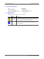
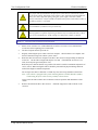
1.4.1 Symbols used
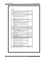
This manual contains these symbols, abbreviations, and terms:
Symbol
10
Heading
Description
Warning
Warns about risk of damage to people or property. Always follow the
instructions provided in conjunction with this symbol.
Note
Calls your attention to problems that may arise if a measure is not taken
or is taken incorrectly.
E-EQ-TRUXCONFIG-D-ARC
2 Installation
2.1
Personal safety
The TX700 User’s Guide and the Tx800 User’s Guide contain important cautions and warnings for
installation and operation of the Trux computer. Please refer to the appropriate manual to review these
cautions and warnings.
2.2
Product safety
2.2.1 Supplying power
Please refer to the “Electrical Installation” section for proper power supply connection. This section can
be found later in this manual as well as in the Tx700 and Tx800 User’s Guides.
2.2.2 Humidity, moisture, cold and heat
Make sure the operating environment is within the standards described in the Tx700 User’s Guide or the
Tx800 User’s Guide.
2.2.3 Interference
Ensure that:
•
Any nearby electrical cabling is run so that interference does not occur.
•
The immediate environment meets requirements stated in the specified standards in the User’s
Guide regarding interference
2.2.4 Vibrations
The Trux computer should be mounted in a way that vibrations do not exceed the limits it is designed for
(see Tx700 User’s Guide or Tx800 User’s Guide).
2.3
Typical usage
Typical usage areas for Trux computers include:
•
Mounted in forklifts, operating in warehouses connected to a logistic system via a wireless
network,.
•
In trucks using global positioning system (GPS) navigation, routes, maps, and picking lists.
•
In forestry machines using GPS-navigation, maps and felling instructions.
E-EQ-TRUXCONFIG-D-ARC
11
Connections and adapters
2.4
Trux Configuration Guide
Connections and adapters
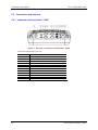
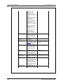
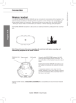
2.4.1 Interfaces and connections, Tx800
Figure 1 Overview connections and interfaces, Tx800
Connections and interfaces (port lid)
12
Position
Function
1
2
3
4
5
6
7
8
9
10
11
12
Power supply (12V DC 50W)
Mic. in
Audio out
COM2 RS232 +12V
COM1 RS232 +5V
VGA (external monitor)
Multipurpose connector (USB 2.0, RS232, +12 V)
RJ-45 Ethernet 10/100 (LAN)
2x USB 2.0
PS/2 Mouse
PS/2 Keyboard
Bluetooth antenna connector
E-EQ-TRUXCONFIG-D-ARC
Trux Configuration Guide
Connections and adapters
2.4.1.1 Under the Tx800 service-lid
Figure 2 Overview: connections and interfaces under the service-lid
Position
1
2
3
4
5
6
Function
USB 2.0
Harddrive
Compact Flash slot (behind HD cable)
Battery/UPS
Mini PCI slot
PC Card slot (option)
E-EQ-TRUXCONFIG-D-ARC
13
Connections and adapters
Trux Configuration Guide
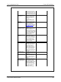
2.4.2 Interfaces and connections, Tx700
Figure 3 Overview connections and interfaces, Tx700
Connections and interfaces
Position
1
2
3
4
5
6
7
8
9
10
11
12
14
Function
Connection for external aerial
Power supply
COM2 (serial port 2) Yellow light indicates 12V out from pin 9
COM1 (serial port 1) Green light indicates 5V out from pin 9
Keyboard/mouse
RJ-45 10/100 LAN
1 х USB 2.0
Connection for multi purpose usage
Audio Out 3.5 mm
Mic In 3.5 mm
Connection for external aerial
Power supply
E-EQ-TRUXCONFIG-D-ARC
Trux Configuration Guide
Connections and adapters
2.4.3 Peripherals and accessories
Listed below are some of the peripherals which can be connected to the Trux computer. More details can
be found in the Tx700 User’s Guide or the Tx800 User’s Guides.
Peripheral
Keyboard
Mouse
Printer
Barcode reader
External monitor
GPS-system
Mobile communication
Headset/Audio out
Microphone
Antennas
E-EQ-TRUXCONFIG-D-ARC
15
Electrical installation
2.5
Trux Configuration Guide
Electrical installation
Always exercise caution when working with electricity!
2.5.1 Connecting to power source
Always exercise caution when working with electricity.
2.5.2 Connecting electrical cables to power sources
The Trux computer comes with a four-meter, four- wired power cable; brown for positive and white for
negative, and 2 conductors; yellow and green, to enable the screen black-out function.
If the black out screen function is not used, see section 2.5.2.1. If the black out function is used, see
section 2.5.2.2.
Connect the brown part of this cable to positive and the white part to negative on the DC/DC converter
power source, and fuse it according to these specifications shown below:
Specifications for electrical supply
Always observe input voltage range specified on the DC to DC power supply
and the optional screen blackout box.
Voltage
12 VDC ± 10% always use insulated DC/DC transformers
Power
50 W
Fuse
5 A (slow blow fuse)
3 A (for optional screen blackout box.
Fuses ARE NOT supplied by Åkerströms.
Then connect the power cable to the computer’s power supply outlet; see Figure 4.
Never connect power to pins 5 or 6, which are for the screen’s black-out function.
Figure 4 Connection for power supply
16
E-EQ-TRUXCONFIG-D-ARC
Trux Configuration Guide
Electrical installation
For proper and safe installation, the input power cable must be connected to a fused
circuit on the vehicle. This fused circuit requires a user supplied 5 Amp maximum time
delay (slow blow) high interrupting rating fuse. If the supply connection is made
directly to the battery, the fuse should be installed in the positive lead within 5 inches of
the battery positive (+) terminal.
For installation by trained service personnel only.
Risk of ignition or explosion. Explosive gas mixture may be vented from battery. Work
only in well ventilated area. Avoid creating arcs and sparks at battery terminals.
How To: Connect Vehicle Electrical Connection
1.
Please review section 2.5.2.1 (without blackout screen box) or section 2.5.2.2 (with blackout
screen box) before beginning power cable install.
2.
The Trux computer must be powered off.
3.
Begin by connecting the power cable to the Trux computer. Work from the Trux computer with
the last connection being to the vehicle’s power source.
4.
Route the cable from the Trux computer to the DC to DC converter and, optionally, the blackout
screen box. Cut the cable to length and strip the wire ends. If the blackout screen box is not
used, do not strip the green and yellow wires.
Route the power cable the shortest way possible. The cable is rated for a maximum temperature of
105°C (221°F). When routing this cable it should be protected from physical damage and from
surfaces that might exceed this temperature.
Do not expose the cable to chemicals or oil that may cause the wiring insulation to deteriorate.
Note: If the vehicle is equipped with a panel containing Silicon Controller Rectifiers (SCR’s),
avoid routing the power cable in close proximity to these devices.
Always route the cable so that it does not interfere with safe operation and maintenance of the
vehicle.
5.
Remove the lid from the DC to DC converter. Attach the stripped wire ends to the DC to DC
converter.
E-EQ-TRUXCONFIG-D-ARC
17
Electrical installation
Trux Configuration Guide
A
DC Input
B
DC Output
C
Looms to secure wiring
The input and output blocks each have two + and two – minus connectors. Either connector in
the block can be used to connect the matching polarity wire.
Use the looms and wire ties to secure all wiring then reattach the cover with the screws.
6.
If the blackout screen box is used, attach the stripped wire
ends to the box. Refer to section 2.5.2.2 and the label on
the blackout screen box for proper wiring connection.
7.
Connect the DC to DC converter to the vehicle’s electrical system.
8.
While observing the fuse requirements specified above, connect the power cable as close as
possible to the actual battery terminals of the vehicle. When available, always connect to
unswitched terminals in vehicle fuse panel, after providing proper fusing.
ATTENTION:
9.
18
For uninterrupted power, electrical supply connections should not be made at
any point after the ignition switch of the vehicle.
If used, connect the wiring for the blackout screen box.
10.
Use proper electrical and mechanical fastening means for terminating the cable. Properly sized
“crimp” type electrical terminals are an accepted method of termination. Please select electrical
connectors sized for use with 18AWG (1mm2) conductors.
11.
Provide mechanical support for the cable by securing it to the vehicle structure at approximately
one foot intervals, taking care not to over tighten and pinch conductors or penetrate outer cable
jacket.
E-EQ-TRUXCONFIG-D-ARC
Trux Configuration Guide
Electrical installation
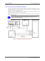
2.5.2.1 DC to DC Converter
Connect the brown part of this cable to positive and the white part to negative on the power source
(DC/DC converter), and fuse it as shown below:
Figure 5 Wiring Diagram, Without Blackout Screen Box
E-EQ-TRUXCONFIG-D-ARC
19
Electrical installation
Trux Configuration Guide
2.5.2.2 DC to DC Converter with Blackout Screen Box
The power supply chassis connector contains two pins that are dedicated to dimming the screen for
example when the vehicle is set in motion (when the gas pedal is pressed). The screen then lights up when
the vehicle stops (when the gas pedal is released).
Connect pins 5 (green conductor) and 6 (yellow conductor) to the vehicle’s gas pedal relay via a
galvanically (electrically) isolated, open/close relay contact.
If the screen’s black-out function is not selected and installed, isolate the end of the green and yellow parts
in the open end of the cable.
You can set this function in the Trux Computer Manager application; see “Trux
Manager” in the following chapter..
Figure 6 Wiring Diagram, With Blackout Screen Box
20
E-EQ-TRUXCONFIG-D-ARC
Trux Configuration Guide
2.6
Mounting the Tx800 port lid
Mounting the Tx800 port lid
Cut the provided openable cable protection tube to the appropriate length. Put the cables in one half of it
and then put the other half on, according to fig. 9.
2.7
Best practice recommendations
2.7.1 Ergonomics
The computer with touch screen shall be mounted in such way that it provides an optimal working
position, without unnecessary physical strain. Ergonomic concern should also be taken to mounting of
peripherals e.g. label printers and bar-code readers. Sometime specific brackets may need to be forged in
order to reach an optimal solution, but commonly various brackets provided by Åkerströms are sufficient.
A configuration with the display in line of sight and easy access to the touch screen is recommended, see
below.
If an external antenna is used, it shall be placed high and not concealed in order to as much as possible
allow free line of sight. Cables shall be as short as possible for minimum losses
2.7.2 Cable Protection
Use a flexible plastic conduit with Chemical resistance to fuels, mineral oils, fats, alkalies, weak acids and
bases etc. to protect the cables. If all cables (new and factory installed) do not fit in the plastic conduit,
fasten them in the conduit with black UV durable bundle bands.
E-EQ-TRUXCONFIG-D-ARC
21
Best practice recommendations
Trux Configuration Guide
2.7.3 Conductors, Terminals and Strain Relief
It is important to use adequate tools in order to be able to make proper termination, cutting and crimping.
Cables and terminals needs to be properly relieved from strains with e.g. bundle bands, in order not to
vibrate loose and cause risk for hardware and personal damage.
2.7.4 Bundle Band (UV- and Oil resistant)
The bundle bands should be resistant to chemical fuels, oils and UV light (black). Fastening of cables shall
be done in such manner that no risk of damage of surrounding equipment is at stake. It is recommended to
attach bundle bands and cables with existing cable to ensure stability and durability.
2.7.5 Conduit Entries and Cable Ports
It is recommended to protect cables in transitions with cable ports. A drilled hole may be very crude and
could inflict severe damage on cables and in the long run the electrical equipment. Depending on
transition, bend radius and material various types exists.
2.7.6 DC/DC Placement and Mounting
The location of the power converter and screen blanking relay is preferably near the truck’s control wiring.
The placement surface shall be smooth and level and preferably on the metal chassis to ensure cooling. The
DC/DC shall be fastened with screws and washers of correct dimension and length to ensure sustainability
against vibration and bumps. If the DC/DC has a lid to better protect the cable terminations, be sure to
reinstall the lid to protect the wiring.
Other considerations are to not mount the DC/DC too far away from the Trux computer and situated in
such place where it is not in the way of operation for the operator.
22
E-EQ-TRUXCONFIG-D-ARC
Trux Configuration Guide
Best practice recommendations
2.7.7 DC/DC Electrical Installation
Before connecting the DC/DC to the vehicle power, one must carefully investigate from where to best
connect. A rule of thumb is that power shall be sourced as close to the battery as possible and not through
common switches e.g. emergency brake and ignition. Please see section 2.5 for details on power supply
connections and applicable warnings and cautions.
2.7.8 Power Cables to Printers and Scanners
It is always recommended to optimize the cable lengths used, but when using pre-crimped cables, typically
when installing peripheral equipment e.g. printers, scanners and other computer connected devices the
length often differs from optimum. Therefore it may be difficult to hide excessive material. In such
situation it is recommended to nicely bundle the cables with bands and find a suitable place for the
package where it is not at risk of being torn, rubbed, friction or affected of other detriment.
E-EQ-TRUXCONFIG-D-ARC
23
Install Mounting Brackets
2.8
Trux Configuration Guide
Install Mounting Brackets
Caution:
This device is intended to transmit RF energy. For protection against RF exposure
to humans and in accordance with FCC rules and Industry Canada rules, this
transmitter should be installed such that a minimum separation distance of at least
20 cm (7.8 in.) is maintained between the antenna and the general population.
This device is not to be co-located with other transmitters.
Several types of mounts are provided for the Tx700 or Tx800. For a complete listing of mounting kits and
the contents of each kit, please refer to the Tx700 & Tx800 accessory catalog. This catalog is available at
www.lxe.com or by contacting your LXE representative.
Tx700 or Tx800 with single RAM ball option
If the Tx700 or Tx800 is ordered with a single RAM ball, available mounting options include:
•
Truck bracket with a single RAM ball (no keyboard mount provision)
•
Truck bracket with a RAM ball for Tx700 or Tx800 mount plus a RAM ball for
keyboard mount
•
RAM ball base with integrated keyboard bracket for back of Tx700 or Tx800.
Tx700 or Tx800 with dual RAM ball option
If the Tx700 or Tx800 is ordered with dual RAM balls, available mounting options include:
•
Truck bracket with a dual RAM balls (no keyboard mount provision)
•
Truck bracket with dual RAM balls for Tx700 or Tx800 mount plus a RAM ball for
keyboard mount
Keyboard mounting options
They keyboard may be mounted using:
•
Integrated keyboard bracket included in some single RAM ball mounting kits
•
A RAM mount using the keyboard ball on some truck brackets
•
A stand alone keyboard mount using a RAM ball attached to the vehicle
Individual brackets
Many individual mounting brackets are also available.
2.8.1 RAM Mount System
The following RAM balls are used to mount the Tx700 or Tx800:
D-sized (2.25”) balls and arms
Used to mount the Tx700 or Tx800 when a single RAM ball is ordered on the back of the Tx700 or Tx800.
A D-sized ball is also used on the truck.
C-sized (1.5”) balls and arms
Used to mount the Tx700 or Tx800 when dual RAM balls are ordered on the back of the Tx700 or Tx800.
A pair of C-sized balls is also used on the truck.
24
E-EQ-TRUXCONFIG-D-ARC
Trux Configuration Guide
Install Mounting Brackets
Keyboard brackets also use C-sized ball. A corresponding C-sized ball is either included as part of the
Tx700 or Tx800 mounting bracket or mounted independently on the truck for the keyboard assembly.
2.8.2 Mounting Procedure
2.8.2.1 Step 1 – Mount Vehicle RAM Ball(s)
Determine the position for mounting the RAM ball(s). Be sure to position the RAM ball(s) to allow
access to the switches and ports on the bottom of the Tx700 or Tx800.
Depending on the options ordered with the Tx700 or Tx800, the RAM ball may be:
•
A single or dual RAM ball mounted directly to the truck
•
A single or dual RAM ball mounted to a plate. The plate then mounts to the truck.
•
A single RAM ball integrated with a mounting plate
•
A single or dual RAM squeeze clamp style ball
•
A single or dual RAM pipe clamp style ball
Additionally, some mounting plates contain a provision for another RAM ball which is used to mount the
keyboard.
Sample mounting options:
Figure 7 Sample RAM Ball Mounting Options
E-EQ-TRUXCONFIG-D-ARC
25
Install Mounting Brackets
Trux Configuration Guide
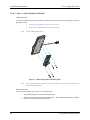
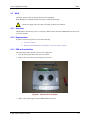
2.8.2.2 Step 2 – Prepare Tx700 or Tx800
The Tx700 or Tx800 is delivered with one or two RAM balls installed depending on the configuration
ordered.
If an integrated keyboard bracket is to be mounted to the rear of the Tx700 or Tx800, follow the procedure
below. Otherwise, skip to the next step.
1.
The Tx700 or Tx800 must be off and the power cord should not be attached during this
procedure.
2.
Place the Tx700 or Tx800 face down on a stable surface.
3.
Remove the RAM ball from the back of the Tx700 or Tx800. The hardware attaching the
RAM ball is not reused.
4.
Install the 2 M5x6 screws in the holes shown below.
Figure 8 Screw Installation, Tx700 or Tx800
26
E-EQ-TRUXCONFIG-D-ARC
Trux Configuration Guide
Install Mounting Brackets
5.
Install the 1.5” (C-size) RAM ball on the keyboard bracket using four M5 locking nuts.
6.
Install the keyboard bracket and the 2.25” (D-Size) RAM ball (removed previously) onto
the back of the Tx700 or Tx800. Use three M5x20 screws with three tapered washers.
E-EQ-TRUXCONFIG-D-ARC
1.
1.5” RAM ball
2.
Locking nut, M5
3.
Integrated keyboard bracket
4.
Screw, M5x20 (DO NOT reuse original screws)
5.
Washer for RAM ball (DO NOT reuse original washers)
27
Install Mounting Brackets
Trux Configuration Guide
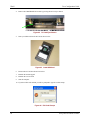
2.8.2.3 Step 3 – Attach Keyboard to Bracket
LXE Keyboards
If using the optional integrated keyboard mount, attach the keyboard to keyboard mounting plate, using the
appropriate screws:
Note:
•
For the 95 key keyboard, use four 8-32x5/8 screws
•
For the 60 key keyboard, use four 10-32x5/8 screws
95-key LXE keyboard shown.
Figure 9 Attach Keyboard to Mounting Plate
Note
Excess keyboard cable length can be looped around the hooks on the bottom of the
keyboard mounting plate.
Other Keyboards
A generic keyboard plate is provided for non-LXE keyboards.
28
1.
Attach the RAM ball to the keyboard mounting plate.
2.
Attach the keyboard to the keyboard mounting plate. The mounting kit DOES NOT include
hardware to attach the keyboard to the plate.
E-EQ-TRUXCONFIG-D-ARC
Trux Configuration Guide
Install Mounting Brackets
2.8.2.4 Step 4 – Attach Tx700 or Tx800 and Keyboard Assembly to RAM Base
Single RAM ball
1.
Use a single D-sized RAM arm to attach the Tx700 or Tx800 assembly to the RAM ball on
the vehicle.
2.
Use a single C-sized RAM arm to attach the keyboard assembly to the C-sized ball on either
the Tx700 or Tx800 keyboard bracket or a C-sized ball on the vehicle.
Dual RAM balls
1.
Use a pair of C-sized arms to attach the Tx700 or Tx800 assembly to the RAM balls on the
vehicle.
2.
Use a C-sized arm to attach the keyboard assembly to a C-sized ball on the vehicle.
2.8.3 Completed Assembly
Samples of completed Tx700 or Tx800 bracket assemblies are shown below
VX89A021KIT21 including
RAM ball base and LXE
keyboard bracket
VX89A025KIT25 including RAM ball base and
generic keyboard bracket
Figure 10 Completed RAM Mount Assembly
E-EQ-TRUXCONFIG-D-ARC
29
Installation of peripherals
2.9
Trux Configuration Guide
Installation of peripherals
Commonly peripherals such as label printers and bar-code readers are used.
Åkerströms Trux AB offers peripherals that facilitate use of the Trux unit. If you order peripherals with the
computer, then the drivers are pre-installed. If you order them later or from a supplier other than
Åkerströms Trux AB, you might have to install the drivers; if so, refer to the peripheral’s documentation.
If you change or re-install the computer’s operating system, you might have to reinstall the pre-installed
drivers.
Examples of keyboard placement on various truck models is found in appendix.
After peripherals are connected, fasten the cables to the bottom of the computer using
cable straps or similar.
2.9.1 Supplying power to peripherals
Some peripherals require power from the computer’s COM or keyboard ports, that is, the scanner and
keyboard with built-in lights.
You can configure the Trux as follow:
•
12 V power is supplied from pin 9 on the COM 2 port
•
5 V power is supplied from pin 9 on the COM 1 port
•
12 V power is supplied from pin 6 on the keyboard/mouse port (Tx700)
•
12 V power is supplied form pin 5 on the multipurpose port (Tx800)
Use the Trux Computer Manager to configure activation of the power supply
For details regarding settings, UPS handling, parameterization of the black-out screen
function and more, please see “Trux Manager” in the following chapter.
30
E-EQ-TRUXCONFIG-D-ARC
3 System Configuration
3.1
Introduction
This chapter provides details on configuring the Trux computer. General Microsoft Windows
configuration options are not covered in this manual. Instead this manual focuses on those aspects of the
Trux computer configuration which may differ from a standard desktop PC.
Refer to this chapter for details on:
•
Soft keyboards
•
Trux Manager Application
•
Wedge
•
Touchscreen.
Wireless configuration, including the 802.11 radio, Bluetooth and WAN, is covered in Chapter 4,
“Wireless Network Configuration”.
3.2
Soft Keyboards
The Tx700 and Tx800 can be ordered with a soft keyboard in a variety of configurations. When the soft
keyboard is ordered, it is installed before the computer is shipped.
Figure 11 Sample Soft Keyboard
E-EQ-TRUXCONFIG-D-ARC
31
Trux Manager
3.3
Trux Configuration Guide
Trux Manager
There are differences in the Trux Manager application depending on the type of Trux computer.
3.3.1 Trux Manager for Tx700
In the Control Panel, click on Other Control Panel Options and then the Trux icon to launch the Tx700
Computer Manager application.
3.3.1.1 Main Tab
The main tab shows the embedded controller’s firmware version and build date as well as the Tx700
computer manager application version and build date. The Åkerströms logo is a clickable hyper link.
There are no user configurable options on this tab.
Figure 12 Tx700 Trux Manager Main Tab
32
E-EQ-TRUXCONFIG-D-ARC
Trux Configuration Guide
Trux Manager
3.3.1.2 General Settings Tab
The General Settings tab provides configuration options for the COM1, COM2 and Multipurpose
Connector ports, Startup and Shutdown options and configuration of the optional defroster.
After making any desired changes, click Apply to apply the new changes or OK to apply the changes and
dismiss the Trux Manager screen.
Figure 13 Tx700 Trux Manager General Settings Tab
COM1 Power
Enable 5VDC power on COM1 pin 9 to power external 5V devices with a maximum power consumption
of 2,5W, 500mA.
If you want the external device to be powered in suspend mode or when the terminal runs on its UPS
battery, you must also select those options.
COM2 Power
Enable 12VDC power on COM2 pin 9 to power external 12V devices with a maximum power
consumption of 6W, 500mA. Options are the same as for COM1.
Mult Purpose Connector
Enable 12VDC power on Multi Purpose Connector COM4 pin 9 to power external 12V devices. Same
power consumption and options as COM2.
COM4 is enabled by default but can be de-selected if necessary.
E-EQ-TRUXCONFIG-D-ARC
33
Trux Manager
Trux Configuration Guide
Startup
Select optional ways to power up the Tx700:
•
by touch panel tap or
•
by applying power to the terminal.
If touch panel tap is selected, you have the possibility to set the tap duration before terminal start time.
Default value is 1 second (1000 ms).
Shutdown
Select touch panel tap as an optional way to shutdown the terminal. You have the possibility to set a tap
duration before terminal shutdown time. Default value is 2 seconds (2000 ms).
Important! When this shutdown option is selected, firmware will issue a power button event. This means
that a touch panel tap performs the same function as the power button. See the Advanced tab of the Power
Options Properties in Windows Control Panel for power button configuration. The default value in a
Tx700 Windows image is shutdown.
Defroster
Enable defroster (heated touch panel). This option is only relevant if the terminal is equipped with an
optional heated touch panel. The default value is defroster enabled.
The defroster will turn off when the temperature goes above 40°C inside the terminal and turn on again
below 39°C (default values).
Note!
Before making any changes to the default values, remember that the temperature outside
the terminal is typically 20°C lower than inside.
Apply Factory Settings
Clicking this button restores all customized settings to their default values after the terminal has been
shutdown and restarted.
34
E-EQ-TRUXCONFIG-D-ARC
Trux Configuration Guide
Trux Manager
3.3.1.3 UPS Tab
The UPS tab contains options for the UPS battery in the Tx700.
After making any desired changes, click Apply to apply the new changes or OK to apply the changes and
dismiss the Trux Manager screen.
Figure 14 Tx700 Trux Manger UPS Tab
UPS Battery
Enable/disable the internal UPS battery. The UPS battery protects the terminal from being shutdown if
there’s a loss of input power.
Configuration
Configure how the terminal should react when/if the input power is lost by enabling UPS functionality:
•
reduce backlight to a certain level after a specified timeout
•
when to safely shutdown the system
UPS Battery Status
Monitor battery states and voltage.
E-EQ-TRUXCONFIG-D-ARC
35
Trux Manager
Trux Configuration Guide
3.3.1.4 Display Backlight Tab
The Display Backlight tab contains options and status for the display backlight.
After making any desired changes, click Apply to apply the new changes or OK to apply the changes and
dismiss the Trux Manager screen.
Figure 15 Tx700 Trux Manager Display Backlight Tab
Blackout-screen Input Signal
Enable Blackout screen functionality.
•
When enabled, the backlight will turn off if there’s a connection between pin 5 and 6 in the
input power connector (yellow and green cable in the power cord.)
•
If the input signal is inverted, enable “Active at input signal low level”.
•
Time delays for backlight on and off is configurable and you can also setup the backlight to
come on again when the signal goes off AND the user taps the touch panel.
•
The touch panel will not send any coordinates to its driver during blackout screen state if
“Quiet touch panel” is enabled.
Backlight Intensity
Monitor backlight intensity 0-100%.
36
E-EQ-TRUXCONFIG-D-ARC
Trux Configuration Guide
Trux Manager
3.3.1.5 Advanced Tab
The Advanced tab provides monitoring for several advanced functions.
There are no user configurable options on this tab.
Figure 16 Tx700 Trux Manager Advanced Tab
On the Advanced tab you can:
•
Monitor the latest POST code sent from the CPU Module BIOS.
•
Monitor driver independent touch panel functionality
•
Monitor the internal temperature at carrier board level.
•
Monitor input and battery power.
E-EQ-TRUXCONFIG-D-ARC
37
Trux Manager
Trux Configuration Guide
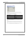
3.3.2 Trux Manager for Tx800
In the Control Panel, click on Other Control Panel Options and then the Trux icon to launch the Tx800
Computer Manager application.
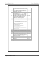
3.3.2.1 Main Tab
The main tab shows the embedded controller’s firmware version and build date as well as the Tx800
computer manager application version and build date. The Åkerströms logo is a clickable hyper link.
There are no user configurable options on this tab.
Figure 17 Tx800 Trux Manager Main Tab
38
E-EQ-TRUXCONFIG-D-ARC
Trux Configuration Guide
Trux Manager
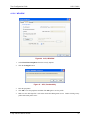
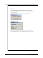
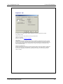
3.3.2.2 General Settings Tab
The General Settings tab provides configuration options for the COM1, COM2 and Multipurpose
Connector ports, Startup and Shutdown options and configuration of the optional defroster.
After making any desired changes, click Apply to apply the new changes or OK to apply the changes and
dismiss the Trux Manager screen.
Figure 18 Tx800 Trux Manager General Settings Tab
COM1 Power
Enable 5VDC power on COM1 pin 9 to power external 5V devices with a maximum power consumption
of 2,5W, 500mA.
If you want the external device to be powered in suspend mode or when the terminal runs on its UPS
battery, you must also select those options.
COM2 Power
Enable 12VDC power on COM2 pin 9 to power external 12V devices with a maximum power
consumption of 6W, 500mA. Options are the same as for COM1.
Multi Purpose Connector
Enable 12VDC power on Multi Purpose Connector COM4 pin 9 to power external 12V devices. Same
power consumption and options as COM2.
COM4 is enabled by default but can be de-selected if necessary.
E-EQ-TRUXCONFIG-D-ARC
39
Trux Manager
Trux Configuration Guide
Startup
Select optional ways to power up the Tx800:
•
by touch panel tap or
•
by applying power to the terminal.
If touch panel tap is selected, you have the possibility to set the tap duration before terminal start time.
Default value is 1 second (1000 ms).
Shutdown
Select touch panel tap as an optional way to shutdown the terminal. You have the possibility to set a tap
duration before terminal shutdown time. Default value is 2 seconds (2000 ms).
Important! When this shutdown option is selected, firmware will issue a power button event. This means
that a touch panel tap performs the same function as the power button. See the Advanced tab of the Power
Options Properties in Windows Control Panel for power button configuration. The default value in a
Tx800 Windows image is shutdown.
Defroster
Enable defroster (heated touch panel). This option is only relevant if the terminal is equipped with an
optional heated touch panel. The default value is defroster enabled.
The defroster will turn off when the temperature goes above 40°C inside the terminal and turn on again
below 39°C (default values).
Note!
Before making any changes to the default values, remember that the temperature outside
the terminal is typically 20°C lower than inside.
Audio
Enable the front speakers. If a louder maximum volume is needed, Enable audio boost will increase the
volume by 5 db.
Apply Factory Settings
Clicking this button restores all customized settings to their default values after the terminal has been
shutdown and restarted.
40
E-EQ-TRUXCONFIG-D-ARC
Trux Configuration Guide
Trux Manager
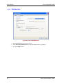
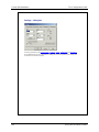
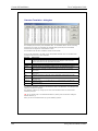
3.3.2.3 UPS Tab
The UPS tab contains options for the UPS battery in the Tx800.
After making any desired changes, click Apply to apply the new changes or OK to apply the changes and
dismiss the Trux Manager screen.
Figure 19 Tx800 Trux Manger UPS Tab
UPS Battery
Enable/disable the internal UPS battery. The UPS battery protects the terminal from being shutdown if
there’s a loss of input power.
Configuration
Configure how the terminal should react when/if the input power is lost by enabling UPS functionality:
•
reduce backlight to a certain level after a specified timeout
•
when to safely shutdown the system
UPS Battery Status
Monitor battery states and voltage.
E-EQ-TRUXCONFIG-D-ARC
41
Trux Manager
Trux Configuration Guide
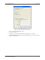
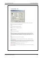
3.3.2.4 Display Backlight Tab
The Display Backlight tab contains options and status for the display backlight.
After making any desired changes, click Apply to apply the new changes or OK to apply the changes and
dismiss the Trux Manager screen.
Figure 20 Tx800 Trux Manager Display Backlight Tab
Blackout-screen Input Signal
Enable Blackout screen functionality.
•
When enabled, the backlight will turn off if there’s a connection between pin 5 and 6 in the
input power connector (yellow and green cable in the power cord.)
•
If the input signal is inverted, enable “Active at input signal low level”.
•
Time delays for backlight on and off is configurable and you can also setup the backlight to
come on again when the signal goes off AND the user taps the touch panel.
•
The touch panel will not send any coordinates to its driver during blackout screen state if
“Quiet touch panel” is enabled.
Light Sensor
Enable the light sensor on the front panel, which will automatically increase or reduce the display
backlight when necessary. Enable lower sensitivity if a smoother behaviour is needed.
Backlight Intensity
Monitor backlight intensity 0-100%.
42
E-EQ-TRUXCONFIG-D-ARC
Trux Configuration Guide
Trux Manager
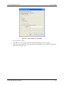
3.3.2.5 Advanced Tab
The Advanced tab provides monitoring for several advanced functions.
There are no user configurable options on this tab.
Figure 21 Tx800 Trux Manager Advanced Tab
On the Advanced tab you can:
•
Monitor the latest POST code sent from the CPU Module BIOS.
•
Monitor driver independent touch panel functionality
•
Monitor the internal temperature at carrier board level.
•
Monitor input and battery power.
E-EQ-TRUXCONFIG-D-ARC
43
Wedge
3.4
Trux Configuration Guide
Wedge
The Trux computer contains a software keyboard wedge that allows scanner input to be treated as
keyboard input by applications.
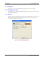
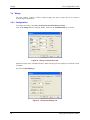
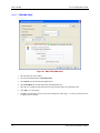
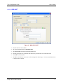
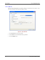
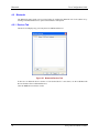
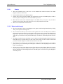
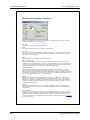
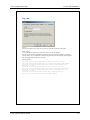
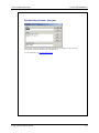
3.4.1 Configuration
To configure the wedge, select Start | All Programs | FreeFloat WLinq | WLinq.
Click on the Settings button to configure WLinq. Make sure the Communication tab is selected.
Figure 22 WLinq Communication tab
Adjust the settings on the communication tab to match the settings for the COM port to which the scanner
is attached.
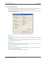
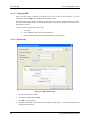
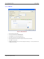
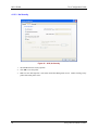
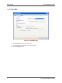
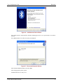
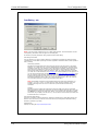
Next click the Data Editing tab.
Figure 23 WLinq Data Editing Tab
44
E-EQ-TRUXCONFIG-D-ARC
Trux Configuration Guide
Touchscreen
Select the proper Data String Termination setting:
•
If the scanner is configured to end a scanned string with a termination character (for example
a CR or LF) click the button for Character(s). Then click the Select.. button and choose the
termination character from the list.
•
If the scanner is not sending a termination character, click the button for Timeout and select
the period in milliseconds.
Click OK to save settings. Click Hide to hide the WLinq information screen.
When WLinq is running, it is indicated by a gray circular icon in the task bar. The icon turns green while
WLinq is processing scanned data or red if there is an error.
To exit the WLinq wedge, click on the taskbar icon then click the Unload button. To restart WLinq,
select Start | All Programs | FreeFloat WLinq | WLinq and click the Hide button.
There are many other options available in WLinq. To learn more, select Start | All Programs |
FreeFloat WLinq | Help for WLinq or review the FreeFloat WLinq documentation included in 6.
FreeFloat WLinq.
3.5
Touchscreen
The Trux computer is equipped with a pressure-sensitive touchscreen. Rather than using a mouse as
pointing device, users select objects by touching the screen with a stylus or a finger.
Always use the accompanying stylus to point, drag or tap the screen. Never use metallic
or sharp-pointed objects.
3.5.1 Using the stylus to select screen objects
To select an object on the interface, gently tap the screen:
•
One time to click.
•
Two times in rapid succession to double-click.
•
Tap on the mouse symbol in the system tray, down in the right corner, the next click will then
be a right click.
3.5.2 Calibrating the touchscreen
Touch-screen accuracy is calibrated using the touch-screen application.
Select Start | All Programs | UPDD | Calibrate.
A series of targets are displayed on screen. Touch the screen at the center of the target. Continue until
the calibration ends. The calibration procedure times out if no user touch is received in 10 seconds.
Configuration options for the touchscreen, as well as online help, can be accessed by selecting Start | All
Programs | UPDD | Settings.
E-EQ-TRUXCONFIG-D-ARC
45
Touchscreen
46
Trux Configuration Guide
E-EQ-TRUXCONFIG-D-ARC
4 Wireless Network Configuration
Several wireless devices may be installed in the Trux computer. The available devices and combinations
may vary by regulatory domain. Available devices include:
4.1
•
An 802.11 radio, either b/g or an a/b/g
•
A Bluetooth radio
•
A WAN card.
802.11 Radio
The 802.11 radio supports several options for wireless security. Select the appropriate section for your
radio type for available configuration and wireless security options.
4.1.1 802.11b/g Radio
The 802.11b/g radio is configured with the Broadcom Wireless Utility (BWU).
accessed by:
The BWU can be
•
Selecting Start | All Programs | Broadcom Wireless | Broadcom Wireless Utility
•
Clicking on the BWU icon in the system tray.
4.1.1.1 Wireless Zero Config
This section assumes the BWU is used to configure the radio. However, it is possible to use the Windows
Wireless Zero Config (WZC) utility to configure the radio.
To use WZC to configure the radio:
•
Start the BWU and select the Wireless Networks tab.
•
Uncheck “Let this tool manage your wireless networks”.
•
Click OK.
The Windows WZC utility can now be used to configure the radio. Please refer to the Help function in
Microsoft Windows XP for more information on using Windows to configure the wireless network
connection.
To return radio control to the BWU, restart the BWU and follow the on screen instructions.
E-EQ-TRUXCONFIG-D-ARC
47
802.11 Radio
Trux Configuration Guide
4.1.1.2 Using the BWU
There are many features contained in the BWU that are not covered in this document.
information, click the Help button displayed on most BWU screens.
For more
The Wireless Network tab displays configuration options and any currently configured connection profiles.
Network profiles display the type of network (infrastructure or ad hoc, the network name) and an icon if
the network is secured.
To create a network profile, follow these steps:
1.
Click Add.
2.
Click “Manually connect to an advanced network”.
3.
Follow the instructions below for the desired network security option.
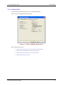
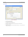
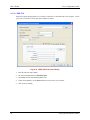
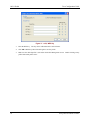
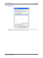
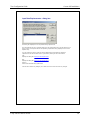
4.1.1.3 No Security
Figure 24 BWU, No Security
48
1.
Enter the Network name (SSID).
2.
Set Network authentication to Open.
3.
Click OK to save the profile.
4.
The BWU automatically connects to the first listed profile within range. Use the Up and Down icons
to adjust the list as desired.
E-EQ-TRUXCONFIG-D-ARC
Trux Configuration Guide
802.11 Radio
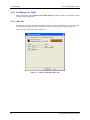
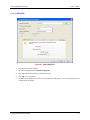
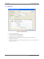
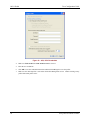
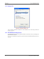
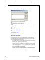
4.1.1.4 WEP
Figure 25 BWU, WEP
1.
Enter the Network name (SSID).
2.
Set Network authentication to Open.
3.
Enter and confirm the network key under Network Key.
4.
Click OK to save the profile.
5.
The BWU automatically connects to the first listed profile within range. Use the Up and Down icons
to adjust the list as desired.
E-EQ-TRUXCONFIG-D-ARC
49
802.11 Radio
Trux Configuration Guide
4.1.1.5 LEAP
Figure 26 BWU, LEAP
50
1.
Enter the Network name (SSID).
2.
Set Network authentication to 802.1X.
3.
Select LEAP from the EAP method pulldown list.
4.
Enter the user credentials and confirm the network password under User Name/Password.
5.
Click OK to save the profile.
6.
The BWU automatically connects to the first listed profile within range. Use the Up and Down icons
to adjust the list as desired.
E-EQ-TRUXCONFIG-D-ARC
Trux Configuration Guide
802.11 Radio
4.1.1.6 WPA-PSK
Figure 27 BWU, WPA-PSK
1.
Enter the Network name (SSID).
2.
Set Network authentication to WPA-Personal (PSK).
3.
Enter and confirm the network key under Network Key.
4.
Click OK to save the profile.
5.
The BWU automatically connects to the first listed profile within range. Use the Up and Down icons
to adjust the list as desired.
E-EQ-TRUXCONFIG-D-ARC
51
802.11 Radio
Trux Configuration Guide
4.1.1.7 PEAP/MS-CHAP
Figure 28 BWU, PEAP/MS-CHAP
52
1.
Enter the Network name (SSID).
2.
Set Network authentication to WPA-Enterprise.
3.
Select PEAP from the EAP method pulldown list.
4.
Select MS-CHAP v2 from the Inner EAP method pulldown list.
5.
Enter the user credentials and confirm the network password under User Name/Password.
6.
Click OK to save the profile.
7.
The BWU automatically connects to the first listed profile within range. Use the Up and Down icons
to adjust the list as desired.
E-EQ-TRUXCONFIG-D-ARC
Trux Configuration Guide
802.11 Radio
4.1.1.8 PEAP-GTC
Figure 29 BWU, PEAP-GTC
1.
Enter the Network name (SSID).
2.
Set Network authentication to WPA-Enterprise.
3.
Select PEAP from the EAP method pulldown list.
4.
Select GTC from the Inner EAP method pulldown list.
5.
Enter the appropriate token username for Logon or identity under Client Identity.
6.
Click OK to save the profile.
7.
The BWU automatically connects to the first listed profile within range. Use the Up and Down icons
to adjust the list as desired.
E-EQ-TRUXCONFIG-D-ARC
53
802.11 Radio
Trux Configuration Guide
4.1.1.9 EAP-TLS
EAP-TLS requires that appropriate server and user certificates are installed on the Trux computer. Please
refer to the “Certificates” section later in this chapter for details.
Figure 30 BWU, EAP-TLS Client Identity
54
1.
Enter the Network name (SSID).
2.
Set Network authentication to WPA-Enterprise.
3.
Select TLS from the EAP method pulldown list.
4.
Under Client Indentify, use the Select button to browse for the user certificate.
5.
Click on Server Identity.
E-EQ-TRUXCONFIG-D-ARC
Trux Configuration Guide
802.11 Radio
Figure 31 BWU, EAP-TLS Server Identity
1.
Check to box to Validate server certificate.
2.
Use the Select button to browse for the server certificate
3.
Click OK to save the profile.
4.
The BWU automatically connects to the first listed profile within range. Use the Up and Down icons
to adjust the list as desired.
E-EQ-TRUXCONFIG-D-ARC
55
802.11 Radio
Trux Configuration Guide
4.1.1.10 WPA LEAP
Figure 32 BWU, WPA LEAP
56
1.
Enter the Network name (SSID).
2.
Set Network authentication to WPA-Enterprise.
3.
Select LEAP from the EAP method pulldown list.
4.
Enter the appropriate user credentials and confirm the password under User Name/Password..
5.
Click OK to save the profile.
6.
The BWU automatically connects to the first listed profile within range. Use the Up and Down icons
to adjust the list as desired.
E-EQ-TRUXCONFIG-D-ARC
Trux Configuration Guide
802.11 Radio
4.1.1.11 EAP-FAST
Figure 33 BWU, EAP-FAST
1.
Enter the Network name (SSID).
2.
Set Network authentication to WPA-Enterprise.
3.
Select EAP-FAST from the EAP method pulldown list.
4.
Enter the appropriate user credentials and confirm the password under User Name/Password.
5.
Click OK to save the profile.
6.
The BWU automatically connects to the first listed profile within range. Use the Up and Down icons
to adjust the list as desired.
E-EQ-TRUXCONFIG-D-ARC
57
802.11 Radio
Trux Configuration Guide
4.1.2 802.11a/b/g Radio
The 802.11b/g radio is configured with the Atheros Client Utility (ACU). The ACU can be accessed by:
•
Selecting Start | All Programs | Atheros | Atheros Client Utility
•
Clicking on the Atheros Client Utility on the desktop
•
Clicking on the ACU icon in the system tray.
Note:
The appearance of the ACU icon in the system tray varies depending on the strength or
lack of an available wireless connection.
4.1.2.1 Wireless Zero Config
This section assumes the ACU is used to configure the radio. However, it is possible to use the Windows
Wireless Zero Config (WZC) utility to configure the radio.
To use WZC to configure the radio:
•
Double click on the network icon in the taskbar.
•
Double click on the wireless connection.
•
Click on View Wireless Networks.
•
Click on Change Advanced Settings.
•
Select the Wireless Networks tab.
•
Check “Let this tool manage your wireless networks”.
•
Click OK.
The Windows WZC utility can now be used to configure the radio. Please refer to the Help function in
Microsoft Windows XP for more information on using Windows to configure the wireless network
connection.
To return radio control to the ACU, uncheck the checkbox.
58
E-EQ-TRUXCONFIG-D-ARC
Trux Configuration Guide
802.11 Radio
4.1.2.2 Using the ACU
There are many features contained in the ACU that are not covered in this document.
information, click the ? button then click on the desired section of the ACU screen.
For more
The Profile Management tab displays any currently configured connection profiles.
To create a network profile, follow these steps:
1.
Click New.
Figure 34 ACU, General Tab
2.
Enter a profile name and an SSID on the General tab.
3.
Click on the Security tab and follow the instructions below for the desired network security option.
E-EQ-TRUXCONFIG-D-ARC
59
802.11 Radio
Trux Configuration Guide
4.1.2.3 No Security
Figure 35 ACU, No Security
60
1.
Select None from Set Security Options.
2.
Click OK to save the profile.
3.
Make sure the desired profile is selected on the Profile Management screen. Double clicking on any
profile makes that profile active.
E-EQ-TRUXCONFIG-D-ARC
Trux Configuration Guide
802.11 Radio
4.1.2.4 WEP
Figure 36 ACU, WEP
1.
Select Pre-Shared Key (Static WEP) from Set Security Options.
2.
Click the Configure button.
E-EQ-TRUXCONFIG-D-ARC
61
802.11 Radio
Trux Configuration Guide
Figure 37 ACU, WEP Key
62
3.
Enter the WEP key. The key can be in Hexadecimal or ASCII format.
4.
Click OK to WEP keys then click OK again to save the profile.
5.
Make sure the desired profile is selected on the Profile Management screen. Double clicking on any
profile makes that profile active.
E-EQ-TRUXCONFIG-D-ARC
Trux Configuration Guide
802.11 Radio
4.1.2.5 LEAP
Figure 38 ACU, LEAP
1.
Select 802.1x from Set Security Options.
2.
Choose LEAP from the 802.1x EAP Type pulldown.
3.
Click the Configure button.
E-EQ-TRUXCONFIG-D-ARC
63
802.11 Radio
Trux Configuration Guide
Figure 39 ACU, LEAP Credentials
64
4.
Make sure Used Saved User Name and Password is selected.
5.
Enter the user credentials.
6.
Click OK to save the credential information and then click OK again to save the profile.
7.
Make sure the desired profile is selected on the Profile Management screen. Double clicking on any
profile makes that profile active.
E-EQ-TRUXCONFIG-D-ARC
Trux Configuration Guide
802.11 Radio
4.1.2.6 WPA-PSK
Figure 40 ACU, WPA-PSK
1.
Select WPA/WPA2 Passphrase from Set Security Options.
2.
Click the Configure button.
Figure 41 ACU, Preshared Key
3.
Enter the passphrase.
4.
Click OK to save the passphrase and then click OK again to save the profile.
5.
Make sure the desired profile is selected on the Profile Management screen. Double clicking on any
profile makes that profile active.
E-EQ-TRUXCONFIG-D-ARC
65
802.11 Radio
Trux Configuration Guide
4.1.2.7 PEAP/MS-CHAP
Figure 42 ACU, PEAP/MS-CHAP
66
1.
Select WPA/WPA2 from Set Security Options.
2.
Choose PEAP (EAP-MSCHAP V2) from the WPA/WPA2 EAP Type pulldown.
3.
Click the Configure button.
E-EQ-TRUXCONFIG-D-ARC
Trux Configuration Guide
802.11 Radio
Figure 43 ACU, PEAP/MS-CHAP Credentials
4.
Make sure User Name and Password is selected.
5.
Enter the user credentials.
6.
Click OK to save the credential information and then click OK again to save the profile.
7.
Make sure the desired profile is selected on the Profile Management screen. Double clicking on any
profile makes that profile active.
E-EQ-TRUXCONFIG-D-ARC
67
802.11 Radio
Trux Configuration Guide
4.1.2.8 PEAP-GTC
Figure 44 ACU, PEAP-GTC
68
1.
Select 802.1x from Set Security Options.
2.
Choose PEAP (EAP-GTC) from the WPA/WPA2 EAP Type pulldown.
3.
Click the Configure button.
E-EQ-TRUXCONFIG-D-ARC
Trux Configuration Guide
802.11 Radio
Figure 45 ACU, PEAP-GTC Credentials
4.
Enter the token User Name.
5.
Click OK to save the credential information and then click OK again to save the profile.
6.
Make sure the desired profile is selected on the Profile Management screen. Double clicking on any
profile makes that profile active.
E-EQ-TRUXCONFIG-D-ARC
69
802.11 Radio
Trux Configuration Guide
4.1.2.9 EAP-TLS
EAP-TLS requires that appropriate server and user certificates are installed on the Trux computer. Please
refer to the “Certificates” section later in this chapter for details.
Figure 46 ACU, EAP-TLS
70
1.
Select WPA/WPA2 from Set Security Options.
2.
Choose EAP-TLS from the WPA/WPA2 EAP Type pulldown.
3.
Click the Configure button.
E-EQ-TRUXCONFIG-D-ARC
Trux Configuration Guide
802.11 Radio
Figure 47 ACU, EAP-TLS Credentials
4.
From the Trusted Root Certification Authorities pulldown, select the appropriate root certification
authority.
5.
From the Select a Certificate pulldown, select the appropriate user certificate.
6.
Click OK to save the certificate information and then click OK again to save the profile.
7.
Make sure the desired profile is selected on the Profile Management screen. Double clicking on any
profile makes that profile active.
E-EQ-TRUXCONFIG-D-ARC
71
802.11 Radio
Trux Configuration Guide
4.1.2.10 WPA LEAP
Figure 48 ACU, WPA LEAP
72
1.
Select WPA/WPA2 from Set Security Options.
2.
Choose LEAP from theWPA/WPA2 EAP Type pulldown.
3.
Click the Configure button.
E-EQ-TRUXCONFIG-D-ARC
Trux Configuration Guide
802.11 Radio
Figure 49 ACU, WPA LEAP Credentials
4.
Make sure Used Saved User Name and Password is selected.
5.
Enter the user credentials.
6.
Click OK to save the credential information and then click OK again to save the profile.
7.
Make sure the desired profile is selected on the Profile Management screen. Double clicking on any
profile makes that profile active.
E-EQ-TRUXCONFIG-D-ARC
73
802.11 Radio
Trux Configuration Guide
4.1.2.11 EAP-FAST
Figure 50 ACU, EAP-FAST
74
1.
Select WPA/WPA2 from Set Security Options.
2.
Choose EAP-FAST from the WPA/WPA2 EAP Type pulldown.
3.
Click the Configure button.
E-EQ-TRUXCONFIG-D-ARC
Trux Configuration Guide
802.11 Radio
Figure 51 ACU, EAP-FAST Authentication
4.
Select MSCHAPv2 User Name and Password from the EAP-FAST Authentication Method
pulldown list.
5.
Check the checkbox for Allow Automatic PAC Provisioning.
6.
Click the Configure button.
E-EQ-TRUXCONFIG-D-ARC
75
802.11 Radio
Trux Configuration Guide
Figure 52 ACU, EAP-FAST Credentials
7.
Make sure Use Saved User Name and Password is selected.
8.
Enter the user credentials.
9.
Click OK to save the credential information, click OK again to save the authentication information
and then click OK again to save the profile.
10. Make sure the desired profile is selected on the Profile Management screen. Double clicking on any
profile makes that profile active.
76
E-EQ-TRUXCONFIG-D-ARC
Trux Configuration Guide
802.11 Radio
4.1.3 Certificates
In order to authenticate with EAP-TLS, the user needs to have the appropriate server and user certificates
installed on the device.
1.
Log into the Certificate Authority webpage.
Figure 53 Install Certificate Chain
2.
Click on Download a CA certificate, certificate chain, or CRL.
3.
Click on install this CA certificate chain.
4.
Go back to the main page.
5.
Click on Request a certificate.
6.
Click on User Certificate.
Figure 54 Request Certificate
7.
Click Submit.
8.
Click Yes on the pop up to request a certificate.
E-EQ-TRUXCONFIG-D-ARC
77
Bluetooth
4.2
Trux Configuration Guide
Bluetooth
The Bluetooth control panel can be accessed either by clicking the Bluetooth icon in the taskbar or by
clicking on the Bluetooth Devices option in the Windows control panel.
4.2.1 Devices Tab
The Devices tab displays any previously discovered Bluetooth devices.
Figure 55 Bluetooth Devices Tab
If there are no Bluetooth devices shown or if the desired device is not shown, use the Add Bluetooth
Device Wizard to discover Bluetooth devices.
Click the Add button to start the wizard.
78
E-EQ-TRUXCONFIG-D-ARC
Trux Configuration Guide
Bluetooth
Figure 56 Add Bluetooth Device Wizard
The wizard cannot be started until the checkbox indicating the device is set up and ready to be found is
checked.
If any Bluetooth devices are discovered, they are displayed.
Figure 57 Discovered Bluetooth Devices
Select the desired Bluetooth device and click Next.
Select the appropriate passkey option.
The Bluetooth device is ready to use.
E-EQ-TRUXCONFIG-D-ARC
79
Bluetooth
Trux Configuration Guide
4.2.2 Options Tab
Figure 58 Bluetooth Options Tab
This tab contains various Bluetooth connection options.
Microsoft Windows help feature.
80
More information can be found using the
E-EQ-TRUXCONFIG-D-ARC
Trux Configuration Guide
Bluetooth
4.2.3 COM Ports Tab
Figure 59 Bluetooth COM Ports Tab
This tab displays the COM ports used by Bluetooth devices, such as the Bluetooth printer illustrated.
More information can be found using the Microsoft Windows help feature.
E-EQ-TRUXCONFIG-D-ARC
81
Bluetooth
Trux Configuration Guide
4.2.4 Hardware Tab
Figure 60 Bluetooth Hardware Tab
This tab hardware information for Bluetooth.
Windows help feature.
More information can be found using the Microsoft
4.2.5 LXE 8652 Bluetooth Ring Scanner
Use the Bluetooth Device Wizard in the Microsoft Windows Control Panel to discover and manager the
Bluetooth scanner connection.
Do not use the ComponentSoft wedge software (provided with the LXE 8650 Bluetooth Ring Scanners) on
the Tx700.
82
E-EQ-TRUXCONFIG-D-ARC
Trux Configuration Guide
4.3
WAN
WAN
Check the contents of the box against the label on the packaging.
Read through these installation instructions before commencing assembly.
!
Connect the supply cable only when everything else has been assembled.
4.3.1 Overview
This document describes the process of inserting a SIM card into the Option GPRS/EDGE/3G PCCard of
your Trux computer.
4.3.2 Requirements
In order to perform this operation you need the following:
•
Torx 20 screwdriver.
•
SIM card with GPRS/EDGE/3G capabilities from your network operator.
4.3.3 SIM card installation
The following procedure describes how to insert a SIM card:
1.
Place the Trux upside down onto a flat clean surface.
2.
Remove the service hatch by loosening the 2 torx screws.
Figure 61 Open the Trux Computer
3.
Remove the antenna pigtail from the GPRS/EDGE/3G PCCard.
E-EQ-TRUXCONFIG-D-ARC
83
WAN
Trux Configuration Guide
4.
Remove the GPRS/EDGE/3G PCCard by pressing the PCCard eject button.
Figure 62 PC Card Eject Button
5.
Insert your SIM card into the PCCard as shown below.
Figure 63 Install SIM Card
6.
Reinsert the PCCard into the PCCard socket.
7.
Reattach the antenna pigtail
8.
Reattach the service hatch.
9.
Start the computer
10. If you have PIN-code enabled you will be prompted to type the code at startup.
Figure 64 PIN Code Prompt
84
E-EQ-TRUXCONFIG-D-ARC
Trux Configuration Guide
WAN
11. Double click the grey/green Option icon in the systray to launch the application
Figure 65 WAN System Tray Icon
12. For some operators the application is automatically configured for the network, if not configure the
settings as advised by your local operator
Figure 66 WAN Network Configuration
13. When all settings are made press the connect button to connect to the preferred network, to disconnect,
press Disconnect.
Figure 67 WAN Disconnect
E-EQ-TRUXCONFIG-D-ARC
85
WAN
86
Trux Configuration Guide
E-EQ-TRUXCONFIG-D-ARC
5 Operating System
If it should become necessary to reload the Microsoft Windows operating system, use the instructions in
the appropriate following section.
5.1
•
To reload the Tx700 or Tx800 with the factory installed operating system, drivers and
utilities, please follow the instructions in section 5.1 System Recovery. You must have the
appropriate Recovery Media for your Trux computer. Please contact your LXE
representative for details.
•
To load a Tx700 or Tx800 with a user installed operating system, please follow the
instructions in section 5.2 Custom OS Installations. You must have Tx700/Tx800 software
drivers CD. Please contact your LXE representative for details.
System Recovery
5.1.1 Recovery Media
System recovery requires the proper recovery media. A DVD containing recovery software is available as
an accessory. The recovery DVD must match the computer type (Tx700 or Tx800), operating system
(Windows XP Professional or Windows XP Embedded) and storage media type (rotating hard drive or
flash).
5.1.2 Recovery Process
The ‘Trux Recovery Solution 2’, hereafter known as TRS, is a method to restore the software on your Trux
to the same state it had when it was shipped from the factory. When TRS is used on your Trux it destroys
any information on your hard disk so please make sure that any information on the hard disk that needs to
be preserved is backed up before using TRS.
In order to use the TRS, the following components are needed:
1.
A Trux capable of booting from a USB mass storage device
2.
A USB DVD player
3.
A TRS DVD suitable for your combination of OS, language and Trux model
The TRS works in the following way:
1.
TRS boots from the TRS DVD via USB
2.
TRS executes the Trux Recovery Wizard 2.0, hereafter known as the Wizard, which guides you
through the rest of the recovery process
3.
TRS partitions and formats the primary disk.
4.
TRS writes an OS image to the primary disk. By default the image from the TRS media is used. In
order to achieve better flexibility and performance, these TRS image files can be put on a network
share instead. To achieve this simply copy the .wim file found in the root on the TRS media to a shared
network folder. Please note that in order to access a shared network folder from TRS you must use
wired Ethernet and the RJ45 port of your Trux and not WLAN.
5.
When the Wizard completes, TRS restarts the system which is now returned to its shipping state in
terms of the installed OS.
E-EQ-TRUXCONFIG-D-ARC
87
System Recovery
5.1.2.1
Trux Configuration Guide
Startup
1.
Attach the USB DVD player to the Trux. Use the standard USB connector instead of the ‘Multi
Purpose Connector’ on Trux 700.
2.
Insert the TRS media into the USB DVD player
3.
Start the Trux. Please note that the BIOS must configured to boot on the USB DVD player. If this is
not the case please modify the boot order in the BIOS of your Trux.
4.
When the Trux boots on the USB DVD player it (the BIOS) asks you to press a key in order to
continue to boot from the TRS media. Please press a key when prompted to boot TRS.
5.
TRS is now booted and the wizard will start
5.1.2.2 Wizard walk-through
88
1.
The first screen shown by the wizard displays some generic and licensing information. By clicking
‘Next’ you accept these licensing terms.
2.
The second screen shown by the wizard is used to gather info on how the TRS process should be
performed. Select the method to be used and the source location of the OS image. By default the OS
image on the TRS media is used. By pressing the button placed on the right side of the field labelled
‘Image File’ you can browse to the preferred OS image if, for instance, it has been placed on a network
share.
3.
The third screen shown by the wizard just lets you confirm the information gathered this far before the
actual TRS process is started. When you click on the ‘Next’ button you will be asked to confirm that
you want to start the TRS process, this is the last chance to abort TRS.
4.
The fourth screen is shown by the wizard during the actual processing and it informs you of what is
going on. This process could take quite a while, up to 30 minutes or more depending on the actual OS
image, USB standard etc.
5.
The last screen of the wizard shows the result of the TRS process. By clicking ‘Finish’ the wizard is
closed. Then press any key to shutdown the computer. Please remove the TRS media when the system
has been shutdown to avoid booting up the Trux into TRS again. You Trux has now gone through the
whole TRS process.
E-EQ-TRUXCONFIG-D-ARC
Trux Configuration Guide
5.2
Custom OS Installations
Custom OS Installations
If desired, a user provided operating system can be installed as opposed to using the LXE supplied
Recovery Media. To use this option, the user must:
•
Provide their own installation source of a supported operating system (Windows XP)
•
Have a valid activation key for that operating system
•
Use the LXE provided drivers CD, TX89A498DRIVERS. It is recommended that the device
drivers CD be available during Microsoft Windows installation and configuration. Since the
Tx700/Tx800 does not have a CD-ROM drive, the device drivers can be copied to a USB
jump drive or accessed via a USB CD drive. The device drivers can also be copied to a
location on the network if a network connection is used to install the Windows OS
E-EQ-TRUXCONFIG-D-ARC
89
Custom OS Installations
90
Trux Configuration Guide
E-EQ-TRUXCONFIG-D-ARC
6 FreeFloat WLinq
The information contained in this appendix is copyright 1998-2007, FreeFloat AB.
E-EQ-TRUXCONFIG-D-ARC
91
Custom OS Installations
Trux Configuration Guide
FreeFloat WLinq
version 3.21
What is WLinq?
WLinq is intended to replace the hardware that is often used in application where data from a
barcode reader should be entered into a program on a pc. The hardware that is often used is called
a decoder (or keyboard wedge).
A decoder converts the signals from a barcode reader to key presses. The decoder is connected
between the keyboard and the CPU with a Y cable. By using WLinq together with a barcode reader
with serial output you get rid of the decoder and the Y cable. WLinq is also easier to set up than a
hardware decoder and makes advanced data editing possible.
Most barcode readers have the capability to send barcode data serially. WLinq uses this fact and is
set up to receive the barcode data on the serial port the barcode reader is connected to. The
received characters are converted to their corresponding keys and are then sent to the active
program's window.
WLinq can be used with other types of hardware that send data serially, like for example scales.
Copyright 1998–2007 FreeFloat AB. All Rights Reserved.
92
E-EQ-TRUXCONFIG-D-ARC
Trux Configuration Guide
Custom OS Installations
Frequently Asked Questions
In this topic we have gathered questions we often get about WLinq. The latest version of this FAQ
is here.
When I read a barcode with 12 characters I would like to add a zero in the beginning of the text.
How do I do it?
How do I do to send Home, End or similar keys?
I want to use ÅÄÖ (or other international characters) in a barcode. How do I do it?
I would like to run two WLinq's, one for COM1 and one for COM2. How do I do it?
In what order does things happen in WLinq?
When I read a barcode with 12 characters I would like to add a zero in the
beginning of the text. How do I do it?
This description assumes you have made all settings in WLinq so you can get the 12 character
code simulated in a program window.
1. Start WLinq if it isn't already running.
2. Click on the Settings button.
3. Click on the Data Editing tab.
4. Click on the Formats button.
5. Click on the Add button.
6. Enter the text Twelwe to thirteen digits in the Name edit box.
7. Enter the text "0" + Input() + "<cr>" in the Data Output Format edit box.
8. Click on the Add button.
9. Make sure Length is selected and that both Min and Max are set to 12.
10. Click on OK until the Data Editing Formats dialog box is displayed.
11. Move the Twelwe to thirteen digits format so it is placed first in the list (use the arrow
buttons to the right of the list to move the selected data editing format).
12. Click on OK in all dialog boxes until the main window is displayed.
13. Test it.
How do I do to send Home, End or similar keys?
Keys in Windows that doesn't have a corresponding character (function keys, arrow keys, Home,
End, and similar) are mapped to ASCII values from 128 and above. In the following example we
show how the Home key can be simulated after each data string:
1. Find out what ASCII value the Home key is mapped to by studying the table Key Codes. We
find that the Home key is mapped to the ASCII value 83 (Note! The codes in the table are
given in hexadecimal notation.)
2. Start WLinq if it isn't already running.
3. Click on the Settings button in the main window.
4. Click on the Data Editing tab.
5
E-EQ-TRUXCONFIG-D-ARC
93
Custom OS Installations
Trux Configuration Guide
5. Click on the Formats button.
6. Select the Default format and then click on the Edit button.
7. Change the text in the Data Output Format edit box to Input() + "\x83". \x83 is a way of
expressing a character ASCII value in hexadecimal instead of writing the actual character.
The character A can for example be written as \x41. When you write codes like these in the
Data Output Format edit box they have to be quoted.
8. Click on OK in all dialog boxes until the main window is displayed.
9. Test it. Note that the Home key is simulated after each data string.
I want to use ÅÄÖ (or other international characters) in a barcode. How do I do
it?
Mostly, international characters can't be encoded in barcodes. Thus you have to use other
characters to represent them and convert them to the correct character in WLinq. An old standard
for encoding the Swedish characters åäö ÅÄÖ is to use the characters }{| ][\. The characters }{|
][\ can the encoded in the bar code type Code 128. The example below show how you can get
WLinq to generate the character å when the character } is received:
1. Start WLinq if it isn't already running.
2. Click on the Settings button in the main window.
3. Click on the Keyboard tab.
4. Click on the Character Translation button.
5. Browse down in the list until you see the character } (ASCII value 125).
6. Select the line for the character }.
7. Click on the Edit button.
8. Click in the Scan Code Tester edit box.
9. Press the key on the keyboard that generates the character å (requires a Swedish keyboard).
10. The text dec 221 hex 0xdd is displayed in the Scan Code Tester edit box. This means that
Windows internally represents the å key with the value 221. Note! This is NOT the ASCII
value for the character å. It is the keyboard scan code. On an english keyboard the same key
generates the [ character.
11. Write 221 in the Key Code edit box.
12. Make sure that the check boxes Active and Affected by Caps Lock are the only ones checked.
13. Click on OK until the main window is displayed.
14. Test by reading a barcode containing the } character.
What we've done above is to tell WLinq that whenever the } character is received it should be
simulated by pressing the key with the keyboard scan code 221. The key with the code 221
generates the å character assuming a Swedish keyboard driver is used in Windows.
I would like to run two WLinq's, one for COM1 and one for COM2. How do I do
it?
WLinq works with what we call profiles. A profile can be given a name and contains all settings you
specify in the Settings dialog box. The settings are com port, the port's speed, string replacement,
data editing formats and so on. Sometimes you want to use a barcode reader on one com port and
some other serial equipment on another port.
94
E-EQ-TRUXCONFIG-D-ARC
Trux Configuration Guide
Custom OS Installations
A common mistake many users do when they want to use more than one profile/com port is to
install WLinq several times. That won't work. Do like this:
1. Create a new profile, give it a name, for example Scanner.
2. Click on the Settings button, select all your settings and then click on OK in the Settings
dialog box.
3. Make sure the profile Scanner is selected, start the Notepad program and test that the
profile is working as intended.
4. Switch back to WLinq and click on Settings. Go to the tab Initialization, check the option
Start WLinq when Windows starts up. Click on OK.
5. Back in the main window of WLinq, create a new profile and give it a new name, for example
Scanner2. Click on the Settings button, select the settings for this profile. At least you
must select a different com port or the two profiles will have a port collision.
6. Test the profile Scanner2 in the same way you tested the profile Scanner.
7. Repeat step 4 except for the profile Scanner2.
8. Restart Windows and check that two instances of WLinq are started automatically. Also check
that WLinq isn't displaying an error message about a com port being busy. Test and see if
both profiles work together.
In what order does things happen in WLinq?
When WLinq receives a data string a lot of checks, replacements and conversions occur. Many
users are interested in understanding the inner workings of WLinq.
Step 1 - Receive the data string from the serial port
How this is done depends on what type of Data String Termination has been selected:
Character: WLinq buffers received characters until the specified termination character is
received. The default termination character is CR (ASCII 13). When WLinq receives the
termination character, WLinq moves to the next step.
Timeout: WLinq buffers received characters until the serial port has been quiet for the
specified period. WLinq will then treat the so far received characters as the data string and
move on to the next step.
Step 2 - Conversion to uppercase/lowercase
In this step letters are converted to uppercase or lowercase according to the setting Case Setting.
Note! Only A-Z and a-z are affected by those conversions.
Step 3 - String replacement
In this step string replacements are done. A string replacement consist of one or more characters
that should be matched and zero or more character the matched string should be replaced with.
You can have several string replacements. They are processed in the order in which they appear in
the Input Data Replacements dialog box. The top-most replacement is processed first.
Step 4 - Matching the data edit format
In this step WLinq will try to find a data edit format that matches the input string. The formats are
processed, beginning with the top-most one, in the order in which they appear in the Data Editing
Formats dialog box. When a format is matched WLinq moves to the next step. Only one format can
be matched.
E-EQ-TRUXCONFIG-D-ARC
95
Custom OS Installations
Trux Configuration Guide
Step 5 - Translation and simulation of key presses
Up to this point all data and expressions are ASCII text. In this step WLinq parses the matched
data edit format's output format. Functions as Left, Mid, and Right are processed to extract parts
of the data string. Please note that the string that were originally received may have been changed
by operations in Step 2 & 3. This step works on the result from those operations.
Text that are to be output has to be converted from ASCII characters to key presses. The
translation is done via the table Character Translation. In the table you can customize what key an
ASCII character should be translated into.
If you've specified one or more window titles in the dialog box Lock Output Window, WLinq will
check if the active window's title matches any of the titles before generating key presses.
96
E-EQ-TRUXCONFIG-D-ARC
Trux Configuration Guide
Custom OS Installations
Platform
The core components of WLinq consist of one .exe file and one DLL file. The DLL file is for Caps
Lock handling. The name of the DLL is CapsLook.dll.
There are some extra components: WLinq Monitor and WLinq Settings Exporter are both used for
troubleshooting. The WLinq File Plugin is an add-on component which enables you to have WLinq's
data stored in text files instead of being simulated as keystrokes.
WLinq can be run in 32-bit Windows environments, that is Windows
95/98/ME/NT/2000/XP/XPe/2003.
E-EQ-TRUXCONFIG-D-ARC
97
Custom OS Installations
Trux Configuration Guide
Changes
Version Change
Date
3.21
Changed the way characters in the range ASCII 32 to
126 are sent. The new way are independent of the
keyboard locale of the PC.
2008-12-11
3.20
Added EAN128 support.
2007-12-03
3.19
Max com port number is now COM256.
2007-10-25
Trigging on a incorrect expression ("<") caused WLinq
to exit with an assertion failure. Now a more user
friendly error message is displayed instead.
If password protection is enabled profiles can't be
deleted.
3.18
Added option for sending prefix and postfix keys before 2007-06-25
and after data (Ctrl+Shift+Alt+1 and
Ctrl+Shift+Alt+2).
3.17
Added logging function. Better for troubleshooting
intermittent problems with configuration/data. Creates
a log file that can be sent to Freefloat for analysis.
2007-03-20
Changed the static text control for OEM into a hyperlink
displaying a text file with OEM information. Credits to
JRTwine Software, LLC for supplying free source code
for this control.
3.16
Added the function Call().
2006-08-16
3.15
Fixed problem with licensing.
2006-08-16
3.14
Internal release
2006-06-01
3.13
When Visual Basic is used to send data out the com
2006-05-19
port via the WLinq message
"WLinq32.SendClipboardContents" it appends two NULL
characters. WLinq stripped one NULL at the end of the
text before, now it strips all trailing NULLs.
3.12
Added blue blinking of tray icon when hardware pin
events are fired.
2006-05-04
3.11
Added the hardware pin events function.
2006-04-18
3.10
Added the messages KeyboardEvents and
NoKeyboardEvents.
2006-03-13
3.9
Added the messages Unsubscribe and
SubscribeExclusively.
2005-12-05
3.8
Added a new clipboard type: "WLinqBinary". It enables
the possibility to send binary data to the com port via
the message "WLinq32.SendClipboardContents".
2005-11-23
Added handling of multiple terminator
characters/string. It is now possible to use for example
"<cr>","<etx>" if you want both <cr> and <etx> to be
terminators of the input data string.
Intercharacter delay is now inter-key delay. If an
intercharacter delay is set, a pause is now made
between each physical key simulated. This was done to
circumvent a bug in Terminal Services which lost
keypresses if they were sent too fast.
3.7
The port was not opened at startup. Fixed.
2005-01-17
3.6
Added the function SubStr().
2004-12-07
Fixed the Hide on startup option.
98
E-EQ-TRUXCONFIG-D-ARC
Trux Configuration Guide
3.5
Custom OS Installations
Using SetProfile verb when WLinq's window was hidden 2004-09-08
caused the active window to lose focus.
The data string terminator can now be more than one
character. There were some minor problems with
scanners using cr/lf as their terminator.
The Initialization String was sent twice at startup. This
error is only present in v3.4.
3.4
Added the File Plugin component.
2004-08-18
Licensing support added for multiple network cards.
WLinq Monitor did not work on Windows 98, fixed. A
small side-effect of the fix is that if a subscriber quits,
WLinq does not go back to keyboard simulation mode.
The help window is no longer modal to the WLinq
window.
The WLinq window now appears in the Taskbar when
the Register dialog is displayed. This makes it easier to
switch to and from the Register dialog.
When logged in as a user with read-only access, it is
possible to switch profile (but not create or change).
WLinq is now installed under the All Users shell context
so an admin can install and configure WLinq and the
user can start WLinq from the Start menu.
When WLinq was started automatically via the option
"Start WLinq when Windows starts up", pressing F1 to
bring up the help file did not work. Fixed.
3.3
Added translation of "<control character name>" and
"<\xNN>" in the match expression for data editing
formats.
2004-05-03
3.2
Removed an internal dependency of a communication
class because it caused problem with a virtual serial
port driver that couldn't handle the port speed of 1200
bps.
2004-01-30
Added extra verification of argument to the function
Mid().
Changed the licensing model.
The real and demo versions are now the same (running
the real version in unregistered mode).
3.1
Added the functions RunApp(), WaitForAppExit(),
2003-04-30
WaitForWindow(), SetFocus(), OpenPort(), ClosePort(),
and SendData() in the data output format.
When WLinq is run by a user, that does not have write
permission in the registry where WLinq saves its
settings, the Settings buttons in the main window is
deactivated. This is to avoid confusion.
3.0
Major changes:
2002-11-14
Faster and smaller installation program.
Added the option Start WLinq when Windows
starts up.
WLinq Monitor, a tool that can be used to
troubleshoot installations. This program displays
E-EQ-TRUXCONFIG-D-ARC
99
Custom OS Installations
Trux Configuration Guide
what is going on in WLinq (input data, string
replacements, data editing format, key
simulations etc.)
WLinq Settings Exporter, a small tool with which
you easily can export WLinq's settings to a text
file. Makes support easier.
Changed the key translation table so it can be
customized also when used with Citrix clients.
Minor changes:
When using the edit box Scan Code Tester the
value is automatically put into the edit box Key
Code.
There is now an alias for the Delay function in the
data output format. It is called Sleep.
2.10
Added the Duplicate String Filter function.
Added an alternative way for WLinq to send data to an
application.
2002-06-17
On the property page Keyboard it was possible to get
two identical error messages if you entered an invalid
value in the edit box Inter-character Delay. Fixed.
2.9
On startup, WLinq erroneously sent a linefeed character 2002-04-03
(ASCII 10) out on the serial port despite that
Initialization String was empty. Certain barcode readers
interpret this as garbage data and can't interpret the
command correctly.
2.8
The function Hide window on incoming data did not
2001-11-20
work. This error was caused by changes in version 2.5.
Added a lite version. In the lite version all data editing
functions has been removed.
2.7
The qualifier keys Shift, Control and Alt did not work in 2001-10-19
Windows 9x/ME. This had the effect that characters
that needed any of the qualifiers did not work. This
fault is present in version 2.5 and 2.6.
Another problem was found and corrected. It had to do
with the Caps Lock keyboard indicator. This was also a
problem only in Windows 9x/ME.
The process of reading the settings from the registry
has been made a lot stricter and when errors occur
very specific error messages are displayed. Hopefully
this will ease troubleshooting and support.
Added the topic Frequently Asked Question.
100
2.6
Added the functions Reboot() and RebootForced() in
the output data format.
2001-09-10
2.5
Added password protection so that users can't change 2001-08-08
the settings or exit WLinq.
Added the possibility to specify a timeout as a data
string terminator.
Added <tab> as an alias to <ht>.
Added control of the signals DTR and RTS.
Added control of the extended status per key to enable
to send a normal Enter and Enter on the numeric
keypad.
A very small memory leak was fixed.
A cosmetic improvement in the dialog box Lock Output
Window.
E-EQ-TRUXCONFIG-D-ARC
Trux Configuration Guide
Custom OS Installations
Fixed a bug that showed itself when running more than
one instance of WLinq and then exited them in a certain
order.
2.4
To solve a problem with older Citrix clients (tested on
4.20.741), hardware scan codes were added to the
characters/keys with the ASCII values 32 to 127, tab,
backspace, shift, control, and alt.
2001-05-07
2.3
The default profile now contains a data editing format
whose single criteria matches all strings. The data
output format is set to Input() + "<cr>". Corrected
some missing translations in the English help. Added
some output data string samples in the help.
2001-04-26
2.2
WLinq stores the setting profiles in the registry under
the key HKEY_LOCAL_MACHINE. Earlier, WLinq
required write-access and could not read in the setting
profiles if a user, that had no write rights to
HKEY_LOCAL_MACHINE, was logged in.
2001-04-06
2.1
Translated help to English.
2001-01-31
2.0
A major update:
2001-01-18
Configurable translation table used for converting
characters to key codes.
String and character replacement.
Data editing formats.
Function for locking output window.
Context-sensitive help.
The tab Special has been removed since it isn't
needed any more.
1.9
Internal version.
2000-10
1.8
Caps Lock support.
2000-08-22
1.7
Never released. Change in project-specific data editing. 2000-08-16
1.6
Yet another project-specific data editing.
2000-08-11
1.5
Project-specific data editing.
2000-06-11
1.4
A change was made so that the internal conversion
2000-05-16
table so that ASCII 29 (GS, group separator) generates
the character "&". Used in EAN128 codes. Function for
sending data back to the hardware equipment
connected to the serial port.
1.3
Smaller changes in the program.
1.2
Support for different profiles. Initialize string and some 1999-06-28
other stuff.
1.1
Serial buffer fix.
1999-02-12
1.0
New version for Win32.
1998-11-16
E-EQ-TRUXCONFIG-D-ARC
2000-05-15
101
Custom OS Installations
Trux Configuration Guide
File Plugin
When you start the File Plugin it subscribes to WLinq's data strings. WLinq stops simulating
keystrokes, instead the File Plugin stores each data string in a separate text file.
The files are stored in the folder selected in the File Plugin. The files are named 1.txt, 2.txt and so
on. No files are overwritten.
If you start the File Plugin when WLinq isn't running you get the following message:
Make sure you start WLinq before starting the File Plugin.
The File Plugin looks like this:
File name, date, time, size, and contents of the last string received from WLinq is displayed.
If you click the button with three dots, you can select the folder where the text files are created.
102
E-EQ-TRUXCONFIG-D-ARC
Trux Configuration Guide
Custom OS Installations
The Main Window
When you start WLinq, the program's main window is displayed:
Profile
Display the currently active profile. To create a new profile, click in the edit box and enter the
name of the new profile. Then click on the Settings button to customize the settings of the profile.
You can automatically select a profile WLinq should use on startup by adding the profile name as
an command line argument to program in the shortcut you use to start WLinq. For example:
"C:\Program\WLinq\WLinq.exe x" where x is the name of the profile.
Delete
Deletes the active profile. The profile Default can't be deleted.
If password protection is enabled, profiles can't be deleted until password protection is turned off.
Unload
Quits the program.
Hide
Hides the main window. WLinq is a program you normally want to run in the background. You can
manually hide the window by using this button. The close button ( ) has the same effect as the
Hide button. So has the Escape key.
Settings
Displays the dialog box Settings, where you customize the active profile.
E-EQ-TRUXCONFIG-D-ARC
103
Custom OS Installations
Trux Configuration Guide
Settings – dialog box
This dialog contains the tabs Communication, Keyboard, Window, Initialization and Data Editing.
On the different tabs you can customize the settings for the currently active profile. WLinq store
the profiles in the Windows registry.
104
E-EQ-TRUXCONFIG-D-ARC
Trux Configuration Guide
Custom OS Installations
Communication – tab
On this tab you specify which serial port WLinq should use and the settings of the serial port.
Port
Specifies the serial port WLinq receive data from.
Speed
Specifies the speed in bps (bits per second).
Data
Specifies the number of data bits per character.
Parity
Specifies the data parity.
Stop
Specifies the number of stop bits.
DTR
Specifies the level of the DTR (Data Terminal Ready) signal. Used in combination with RTS to
signal status (handshaking) to equipment connected to the com port. Certain kinds of hardware
requires that the DTR and RTS are high before any communication will take place. The
communication speed of certain special hardware are configured by different settings of DTR and
RTS.
RTS
Specifies the level of the RTS (Request To Send) signal.
Default
Resets the serial port to COM1 and its settings to 9600, 8, No parity, 1, DTR=High, RTS=High.
Duplicate String Filter
Specifies whether WLinq should filter duplicate data input strings. If this setting is active, WLinq
will check the received data input string and if it is the same as the previous data input string and
the specified time hasn't elapsed, the string will be filtered (removed).
Hardware Pin Events
Configure serial port hardware signals to generate events.
Note! The hardware you connect to the serial port must be set to use the same speed, data bits,
parity, and stop bits.
E-EQ-TRUXCONFIG-D-ARC
105
Custom OS Installations
Trux Configuration Guide
Hardware Pin Events – dialog box
In this dialog you configure which changes on the serial port handshake signals that should
generate events.
The signals that are monitored are CTS, DSR, RI, and DCD. A string can be sent when the signal
goes high or when it goes low or for both types of change.
For each type of change and signal, a certain string is generated:
Signal and Change
CTS High
CTS Low
DSR High
DSR Low
RI High
RI Low
DCD High
DCD Low
String
[CTS_HIGH]
[CTS_LOW]
[DSR_HIGH]
[DSR_LOW]
[RI_HIGH]
[RI_LOW]
[DCD_HIGH]
[DCD_LOW]
You can use the string to trigger a data editing format or use a string replacement to specify the
output you want when the change happens.
Example
Let's say you want WLinq to send the text "CTS went high" when the signal CTS goes high. Click on
the Hardware Pin Events button on the Communication tab and check the CTS High box. Click on
OK.
Now select the Data Editing tab and then on the Replacements button. In the box Search for, enter
"[CTS_HIGH]" (do not include the quotes) and in the box Replace with, enter "CTS went high".
106
E-EQ-TRUXCONFIG-D-ARC
Trux Configuration Guide
Custom OS Installations
Keyboard – tab
On this tab you can adjust various settings that affect how WLinq simulates key presses.
Inter-character Delay
Specifies how long the delay between each key press should be.
Character Translation
Displays the dialog box Character Translation.
Case Setting
Specifies how letters are handled. If set to Normal, the letters are passed through with no special
conversion. For example, if the string aBc is received, WLinq simulates the key presses so aBc will
be entered in the active program. If set to Uppercase the string aBc will be simulated as ABC and if
set to Lowercase the string will be simulated as abc. Please note that this is independent of the
current Caps Lock setting.
Send Pre- and Postfix Keys
Specifies whether WLinq should send a prefix key before data is output and a postfix key after data
is output. The prefix key is Ctrl+Shift+Alt+1 and the postfix key is Ctrl+Shift+Alt+2. This option
can be used in applications customized to recognize when a string is sent from WLinq (barcode
reader or similar).
E-EQ-TRUXCONFIG-D-ARC
107
Custom OS Installations
Trux Configuration Guide
Character Translation – dialog box
The list displayed in this dialog is the translation table. The translation table is used for converting
characters to key codes. By customizing the translation table, special keys and international
characters can be assigned to certain character values.
The translations that has been modified is marked with an asterisk.
There are 256 translations in the table, one for each possible character value. In the table below
the different columns in the list are described.
Column
Character
ASCII
Key Code
Active
Shift
Ctrl
Alt
Caps
Diacritic
Extended
Description
The character the translation is for. For the characters with ASCII values between
0 and 31 the names of the control characters are displayed. This is because
control characters can't be represented as symbol.
The ASCII value of the character. Both decimal and hexadecimal.
The key code the character is translated into.
Specifies whether the translation is active or not. The characters that doesn't
have an active translation is filtered and doesn't generate any key presses.
Specifies if the Shift key should be used in combination with the basic key code
(Key Code ).
Specifies if the Ctrl key should be used in combination with the basic key code
(Key Code ).
Specifies if the Alt key should be used in combination with the basic key code
(Key Code ).
Specifies if the character/key is affected of the Caps Lock key. This is only used
for letter keys.
Specifies if the key is a so called dead key. See Edit Character Translation for
more information.
Specifies if the key should have extended status set.
To customize a translation, select it in the list and then click on the Edit button. The dialog box Edit
Character Translation is displayed.
The OK button confirms any changes you've made in the translation table. The Cancel button
cancels any changes.
Tip! You can quickly jump to a customized translation by clicking in the list and then writing the
asterisk character (*).
When you click on the Default button you get the following question:
108
E-EQ-TRUXCONFIG-D-ARC
Trux Configuration Guide
Custom OS Installations
Click on Yes if you want to reset the translation table to its default setting. Please note that all
customizations of the table will be lost.
E-EQ-TRUXCONFIG-D-ARC
109
Custom OS Installations
Trux Configuration Guide
Edit Character Translation – dialog box
This dialog box displays the settings for the translation you selected before you clicked the Edit
button in the dialog box Character Translation.
Character
The character or the name of the control character.
ASCII
The character's ASCII value. Both in decimal and hexadecimal.
Key Code
Here you enter the key code the character should be translated to. You should enter the key code
in decimal. The key code is dynamically converted and displayed in hexadecimal notation to the
right of the key code input box.
Active
Specifies whether this translations should be active or not.
Shift, Control, and Alt
Specifies whether these keys should be used in combination with the key code. Example: The
translation for the exclamation sign (!) has the key code corresponding to the key marked with a
one and an exclamation sign. Up to the left on the keyboard. But to generate an exclamation sign
the Shift key has to be pressed and held down before the key is pressed.
Affected by Caps Lock
Specifies if the key is affected by the Caps Lock setting. Example: The character A is normally
(Caps Lock=off) generated by pressing the Shift key and then the A key. But if Caps Lock is on
then a lower case a will be generated. The A key is affected by the Caps Lock setting and needs to
have the check box Affected by Caps Lock checked. If not, the character generated will depend on
the Caps Lock settings which mostly is an unwanted effect.
Diacritic
Specifies if the character is a so called dead key. For example, on a Swedish keyboard there are
two dead keys. These are the keys with which one writes the characters ¨^~´`. If you check
Diacritic an extra space is simulated so the diacritic character alone is generated. Otherwise the
diacritic key is used in combination with the next key pressed/simulated. (by pressing ¨ and then
O generates the character Ö).
Extended
Specifies if the key is an extended key. For example, the Return key and the Enter key on the
numeric keyboard has the same key code. The thing that differs between them is that Enter is an
extended key.
Scan Code Tester
If you click in this box and then presses a key on the keyboard, the key code for the key will be
displayed. The code is displayed in both decimal and hexadecimal notation. This does not work for
certain characters. For example, the Escape, Return and Tab key and some other special keys
won't work because they are special system keys or used for navigating in the GUI. See Key Codes
for a list of key codes.
110
E-EQ-TRUXCONFIG-D-ARC
Trux Configuration Guide
Custom OS Installations
Click on OK to confirm any changes you've made or click on Cancel to cancel any changes.
E-EQ-TRUXCONFIG-D-ARC
111
Custom OS Installations
Trux Configuration Guide
Window – tab
On this tab you can customize how WLinq's window behaves and what windows key presses should
be sent to.
Hide on startup
Specifies if you want WLinq's main window to be hidden on startup.
Hide window automatically on incoming data
If this box is check the main window will be hidden when data is received on the serial port.
Lock output window
If this box is check and you specify one or more window titles in the dialog box Lock Output
Window key presses will only be sent to the active window if the window's title matches any of the
specified window titles.
Setup
Displays the dialog box Lock Output Window.
Set password
Displays the dialog box Set password.
112
E-EQ-TRUXCONFIG-D-ARC
Trux Configuration Guide
Custom OS Installations
Lock Output Window – dialog box
Here you can specify one or more window titles. WLinq tries to match the window titles against the
window title of the active program. If any title is matched then WLinq will send key presses to the
window. But if none of the specified titles matches the title of the active program's window, no key
presses will be sent to the window.
You can use the wild card characters * and ?. * matches zero or more characters. ? matches
exactly one character. The expression "*Notepad" matches window titles that end with "Notepad",
for example "Untitled - Notepad". It is necessary to be able to use these kind of expressions if a
program uses the current document name as part of its window title.
You add a new window title by entering it in the edit box and then clicking the Add button. You
delete a window title by selecting it in the list and then clicking on the Remove button.
Click on OK when you're finished.
E-EQ-TRUXCONFIG-D-ARC
113
Custom OS Installations
Trux Configuration Guide
Set Password – dialog box
In this dialog box you can specify a password. The password is used to stop unauthorized users
from changing the settings or quitting WLinq. In other words a function for decreasing the need for
support after installation.
To remove password protection, leave the box Password empty and click on OK.
When you've specified a password, the dialog box Enter Password will be displayed the next time
you click on the button Settings or Unload in the main window.
Click on OK when you've specified a password.
114
E-EQ-TRUXCONFIG-D-ARC
Trux Configuration Guide
Custom OS Installations
Enter Password – dialog box
This dialog box is displayed when you click on the button Settings or Unload in the main window
when password protection is active. You should enter the correct password.
If you enter the wrong password, you can't quit WLinq or change the settings.
Click on OK when you've specified the password.
E-EQ-TRUXCONFIG-D-ARC
115
Custom OS Installations
Trux Configuration Guide
Initialization – tab
Initialization String
The string specified here will be sent out on the serial port when WLinq starts. This might be useful
if the hardware connected to the serial port need some kind of start command before it starts
working.
You can click on the Remove button to empty Initialization String.
Start WLinq when Windows starts up
If you check this box WLinq will be started (with the current profile) when Windows is started. You
can check this box for more than one profile, just make sure the profiles user different com-ports.
For administrators: Start WLinq when Windows starts up creates a key under
HKEY_LOCAL_MACHINE\Software\Microsoft\Windows\CurrentVersion\Run which is used for all
users that logs on to the pc. Any keys created by this function will be removed when uninstalling.
Tip! In Windows NT's file BOOT.INI you can add the option /NoSerialMice. Then Windows NT
won't scan for mice on the serial port. The scanning confuses certain types of hardware. Example:
[boot loader]
timeout=3
default=multi(0)disk(0)rdisk(0)partition(1)\WINNT35
[operating systems]
multi(0)disk(0)rdisk(0)partition(1)\WINNT35="Windows NT Workstation
Version 3.51" /NoSerialMice
multi(0)disk(0)rdisk(0)partition(1)\WINNT35="Windows NT Workstation
Version 3.51 [VGA mode]" /basevideo /sos /NoSerialMice
116
E-EQ-TRUXCONFIG-D-ARC
Trux Configuration Guide
Custom OS Installations
Log – tab
Log File
Enter the full path and name of the file in which you want data and events to be logged.
Enable Logging
If you check this box WLinq will log data and events to the log file specified.
A log file can be used for troubleshooting especially tricky and intermittent problems. The logging
can be turned on to record data and events over long periods of time and hopefully capturing some
data or garbage causing problems in the setup.
Sample log data:
2007-03-08 11:13:30.214
2007-03-08 11:13:30.230
2007-03-08 11:13:30.230
wlinqlog.txt - SciTE
2007-03-08 11:13:31.668
2007-03-08 11:13:31.668
2007-03-08 11:13:31.668
wlinqlog.txt - SciTE
2007-03-08 11:16:15.114
2007-03-08 11:16:15.114
E-EQ-TRUXCONFIG-D-ARC
RAW INPUT DATA: 42 30 38 37 33 31 30 35 35 34 31
Locked Window(s) Not Active: Input String = B0873105541
Locked Window(s) Not Active: Current Window's Title =
RAW INPUT DATA: 42 30 38 37 33 31 30 35 35 34 31
Locked Window(s) Not Active: Input String = B0873105541
Locked Window(s) Not Active: Current Window's Title =
Connected: Program Info = FreeFloat WLinq 3.17
Connected: Active Profile = Default
117
Custom OS Installations
Trux Configuration Guide
Data Editing – tab
Note! In the lite version of WLinq there are no data editing formats. The Formats button and the
corresponding Test button does not appear on this dialog tab.
On this tab you specify settings for string replacement and data editing.
Data String Termination
Here you specify if you want a certain character or characters to terminate the data input string
(Character(s)) or if the data input string should be regarded as terminated after a certain period of
time (Timeout).
Character(s) (default)
Specifies the character that WLinq uses to find the end of a data input string. The default
setting is <cr> (ASCII value 13). CR is an abbreviation of Carriage Return. The data string
terminator can be set to any character value. Note that the terminator must be the same in
WLinq and in the hardware you connect to the serial port. In setup manuals to barcode
scanners this setting is often called post-amble or suffix. To change Data String Terminator
you enter one or more characters (use mnemonics for control characters) in the input box or
you can click the Select button to display the dialog box Select Data String Terminator which
lets you choose a single character. Please note that data string terminator is removed from
incoming data. Example: The string 123<CR><LF> is received on the serial port and the
data string terminator is set to <CR><LF>. WLinq will trim away the <CR><LF> from the
end of the string before any further data processing takes place.
Note! It is possible to specify several characters/strings as a data string terminator. For
example: "<cr><lf>","<etx>". In these cases you enter the string manually in the box
instead of selecting it from the list. You should use quotes around each data string
terminator.
Timeout
Specifies the period of time after which WLinq thinks the data input string is terminated.
When this option is selected the equipment you connect to WLinq should not have any suffix
set. Note! If you specify a too high value (approx. 1000 ms) the user will think the reading
time is slow. If you specify a too low value (< 30 ms) there's a risk the data input string will
be divided into two or more parts.
Filter Unknown Data Strings
If this box is checked, incoming data strings, that aren't matched by any data editing format, are
filtered. This is nice when you want to have control and only let strings that match data editing
formats to generate key presses.
Replacements
Displays the dialog box Input Data Replacements.
118
E-EQ-TRUXCONFIG-D-ARC
Trux Configuration Guide
Custom OS Installations
Test (to the right of the Replacements button)
Displays the dialog box Test Input Data Replacements.
Formats
Displays the dialog box Data Editing Formats.
Test (to the right of the Formats button)
Displays the dialog box Test Data Editing Formats.
E-EQ-TRUXCONFIG-D-ARC
119
Custom OS Installations
Trux Configuration Guide
Select Data String Terminator – dialog box
Here you can select the character that should be used as a data string terminator. Select the value
in the list and then click on the OK button. If you don't want to change the data string terminator,
click on Cancel. For more information about the data string terminator, please see Data Editing –
tab.
Note that if your data string terminator consist of more than one character you need to enter in
manually, you cannot use this dialog for terminators of more than one character.
120
E-EQ-TRUXCONFIG-D-ARC
Trux Configuration Guide
Custom OS Installations
Input Data Replacements – dialog box
This dialog box displays the currently defined string replacements.
The strings WLinq scan for in incoming data are in the column Search for in the list. When such a
string is found, it is replaced with its corresponding replacement string (displayed in the column
Replace with).
You can change the order in which the string replacements are processed by selecting a
replacement in the list and then move it up or down by clicking on the arrow buttons.
Add
Displays the dialog box Add Input Data Replacement.
Edit
Displays the dialog box Edit Input Data Replacement.
Remove
Removes the selected string replacement.
Click on OK to confirm any changes you've made or click on Cancel to cancel any changes.
E-EQ-TRUXCONFIG-D-ARC
121
Custom OS Installations
Trux Configuration Guide
Add Input Data Replacement – dialog box
This dialog is used for adding a string replacement.
Search for
Specify the string you want WLinq to search for. The Search for box can't be left empty.
Replace with
Specify the string you want WLinq to replace search string with.
Click on OK if you want to confirm the new string replacement.
Tip! If you leave the Replace with box empty, the string replacement will work as a filter. Both
substrings and single characters may be filtered in this way.
122
E-EQ-TRUXCONFIG-D-ARC
Trux Configuration Guide
Custom OS Installations
Edit Input Data Replacement – dialog box
This dialog box is used for changing an existing string replacement.
Search for
The string you want WLinq to scan for.
Replace with
The string you want WLinq to replace with.
Click on OK to confirm any changes you've made or click on Cancel to cancel any changes.
E-EQ-TRUXCONFIG-D-ARC
123
Custom OS Installations
Trux Configuration Guide
Test Input Data Replacements – dialog box
In this dialog box you can test the currently defined string replacements. In the example above a
string replacement has been defined. The string replacement searches for the character @ and
replaces it with the string Rob.
Test
Click on this button after you have entered the string to test.
Enter Data String To Test
In this box you should enter the string you want to test.
Number of replacements
Displays the number of replacements done.
Data Output
Displays the result after all defined string replacements has been processed.
Click on the Close button when you're finished testing.
124
E-EQ-TRUXCONFIG-D-ARC
Trux Configuration Guide
Custom OS Installations
Data Editing Formats – dialog box
In this dialog box there's a list over the currently defined data editing formats. You can add, edit,
delete, and change the order in which the data editing formats are processed.
Add
Display the dialog box Add Data Editing Format.
Edit
Display the dialog box Edit Data Editing Format.
Remove
Removes the selected data editing format.
Click on OK to confirm any changes you've made or click on Cancel to cancel any changes.
E-EQ-TRUXCONFIG-D-ARC
125
Custom OS Installations
Trux Configuration Guide
Add Data Editing Formats – dialog box
This dialog is used for defining a new data editing format.
Name
Here you specify the name of the data editing format.
Criteria
This list shows the criterias of the data editing format.
Data Output Format
The data editing formats output format. There are more information about this further down in this
topic.
Add
Displays the dialog box Add Criteria.
Edit
Displays the dialog box Edit Criteria.
Remove
Removes the selected criteria.
Click on OK to confirm any changes you've made or click on Cancel to cancel any changes.
What is a data editing format?
A data editing format has a name, one or more criterias, and one data output format. WLinq uses
the data editing formats to extract, remove and add information to the incoming data strings.
A data editing format must have at least one criteria. There are three types of criterias: length
criterias, expression criterias, and EAN128 criterias.
A length criteria consists of a minimum length and a maximum length. A length criteria is
met when the input data string's length is longer than or equal the given minimum length
AND shorter than or equal to the given maximum length.
An expression criteria consist of a start position and an expression. The start position
specifies the position in the input data string where WLinq will try to match the expression.
The expression consists of the characters that should be present in the input data string
from the start position and forward. You can use the wild card character ? to represent any
one character. The wild card character * matches zero or more characters. Example: start
position = 3, expression = 3?5 will match the strings 12345, 123x5 och AB3Z5 but the
strings 12346, 12A45, and 1235 won't be matched.
An EAN128 critera consists of two lists of field identifiers. One list specifies the fields that
must be present in the data string and the other list specifies the fields that must not be
126
E-EQ-TRUXCONFIG-D-ARC
Trux Configuration Guide
Custom OS Installations
present.
A data editing format has an output format. The output format specifies the information that
should be generated when all the format's criterias are met. The output format is made up of
constant strings and/or string functions that extracts parts of the input data string. In the
examples below, the input data string is 12345ABCDE.
Example
"ABC"
Left( 3 )
Right( 3 )
Mid( 3, 2 )
Mid( "A", 5 )
Mid( 6 )
SubStr( "23", "CD" )
EAN128Field( "02" )
Delay( 1000 )
Sleep( 1000 )
Input()
Date( "%Y-%m-%d"
)
E-EQ-TRUXCONFIG-D-ARC
Description
Constant string with
ordinary characters
Extracts the specified
number of characters from
the beginning of the string.
Extract the specified
number of characters from
the end of the string.
The first digit specifies the
character position and the
second specifies the
number of characters.
Extracts the specified
number of characters
starting at the specified
position.
This is another way of
specifying the starting
position. The substring's
position in the input data
string is used as the
starting position for the Mid
function.
If only the start position is
specified, extracts all
character from the start
position to the end of the
string.
Scans for the first string
and extracts all characters
up to the second string. If
the first string isn't found,
the result is an empty
string.
Extracts the data of the
field 02 from an EAN128
code. If the field doesn't
exist, the expression results
in an empty string.
This is how you insert a
delay in the output data
format. The time is
specified in milliseconds.
Sleep is an alias of Delay.
Represents the entire input
data string.
Inserts the current date in
the specified format. The
supported date and time
formats:
%a Weekday
(abbrevieated)
%A Weekday
%b Name of month
((abbrevieated)
%B Name of month
%d Day in month (01 –
31)
Result
ABC
123
CDE
34
ABCDE
ABCDE
45AB
12345ABCDE
2001-01-23
127
Custom OS Installations
Trux Configuration Guide
Time( "%H.%M" )
"X" + Left( 2 ) +
Right( 2 )
"<cr><tab>"
"\x09"
"\d013"
Input() +
"<tab>1<cr>"
Reboot()
RebootForced()
128
%H Hours in 24 hour
format (00 – 23)
%I Hours in 12 hour
format (01 – 12)
%j Day in year (001 – 366)
%m Month as number (01
– 12)
%M Minute (00 – 59)
%p A.M./P.M.-indicator for
12 hour format
%S Seconds (00 – 59)
%U Week number with
Sunday as the first day of
week (00 – 53)
%w Weekday as decimal
number (0 – 6; Sunday is
0)
%W Week number with
Monday as the first day of
week (00 – 53)
%y Year without century
(00 – 99)
%Y Year with century
(1999, 2000, ... )
%% The percent sign
Other characters, for
example .-/, can be used.
Inserts the current time in
the specified format. Time
is just a synonym for Date.
It is the contents of the
format string that affects
the result.
Different expressions can
be combined.
Control characters are
specified within <>. See
Characters for the codes
that can be used. They are
in the column Abbreviation.
You can specify control
characters and character
codes by entering the \x
prefix followed by their
hexadecimal code (two
digits).
You can specify control
characters and character
codes by entering the \d
prefix followed by their
decimal code (three digits).
The entire input data string,
the Tab key, a one, the
Enter key.
Closes all programs and
restarts the pc. If a
program has a document
that hasn't been saved that
program will display a
question whether you want
to save the document or
not. This stops the reboot
process until you answer
the question.
Closes all programs and
restarts the pc. When this
function is used no unsaved
13.20
X12DE
[ENTER][TAB] (The Enter
key is pressed and then the
Tab key)
[TAB]
[ENTER]
12345ABCDE[TAB]1[ENTER]
E-EQ-TRUXCONFIG-D-ARC
Trux Configuration Guide
RunApp(
"notepad.exe" )
SetFocus(
"*Notepad" )
WaitForWindow(
"*Notepad", 3000 )
WaitForAppExit(
30000 )
OpenPort()
ClosePort()
SendData( "abc" )
SetProfile( "Other" )
Call( "extapp.exe",
"c:\temp\input.txt",
"c:\temp\output.txt"
)
E-EQ-TRUXCONFIG-D-ARC
Custom OS Installations
documents will be saved.
All programs are shut down
in a very abrupt way. Use
this function only if you are
aware of the consequences!
Starts the specified
program. To be sure that
the started application's
window is activated, use
RunApp(),
WaitForWindow(), and
SetFocus() in the given
order.
Activates the first window
that has a caption that
matches the window
caption pattern. Please see
Lock Output Window for a
description on the pattern
format.
Waits until a window with a
matching caption is found.
3000 is a timeout (in
milliseconds) that specifies
how long WLinq will wait for
the window to appear. Zero
means no timeout, that is
WLinq will wait until the
window appears.
Waits until the program
started with RunApp() is
exited. 30000 means that
WLinq will give up waiting
after 30 seconds. Zero
means no timeout, that is
WLinq will wait until the
program is exited.
Opens the serial port.
Closes the serial port.
ClosePort() and OpenPort()
is needed when a data
output format starts a
program that uses the
same serial port as WLinq
does. You can then close
the serial port, start the
program, wait until it exits,
and then open the serial
port again.
Sends the characters abc to
the device connected to the
serial port.
Activates another profile.
Useful if you want to be
able to select dynamically
between two or more
profiles.
Outputs the current input
string to the file input.txt,
then starts the external
application extapp.exe. The
external application reads
the data from input.txt,
processess it and outputs
the result to output.txt.
Then the external
application exits. WLinq
129
Custom OS Installations
Trux Configuration Guide
reads the result from
output.txt which becomes
the value of the function
call.
Note! The first argument
may refer to an executable
file or and executable file
with an argument. For
example: "rubyw script.rb".
130
E-EQ-TRUXCONFIG-D-ARC
Trux Configuration Guide
Custom OS Installations
Add Criteria – dialog box
In this dialog box you define a new criteria. Note that you can define only one length criteria per
data editing format. If you try to define more than one, an error message will be displayed when
you click OK.
Length
Choose this to define a length criteria.
String
Choose this to define an expression criteria.
Min
The minimum length of the input data string.
Max
The maximum length of the input data string.
Start position
The position in the input data string where the scan for the string expression starts.
Expression
The string expression that should be matched. Control character mnemonics and <\xNN> format
can be used.
EAN128
Choose this to define a EAN128 criteria.
Fields that must be present
Specifies the EAN128 fields that must be present in the data string for this criteria to match. Enter
a single field identifier or a list of field identifiers separated by a comma. For example: 20,37
Fields that must NOT be present
Specifies the fields that if they are present, will make the critera not to match the data string. The
same rules apply as for Fields that must be present.
Click on OK to confirm any changes you've made or click on Cancel to cancel any changes.
E-EQ-TRUXCONFIG-D-ARC
131
Custom OS Installations
Trux Configuration Guide
Edit Criteria – dialog box
This dialog box is used when changing an existing data editing format criteria. See Add Criteria for
more information.
132
E-EQ-TRUXCONFIG-D-ARC
Trux Configuration Guide
Custom OS Installations
Edit Data Editing Formats – dialog box
This dialog box is used for changing a data editing format. You can change the name of the data
editing format, specify its criterias and the ouput data format.
For more information, see Add Data Editing Format.
E-EQ-TRUXCONFIG-D-ARC
133
Custom OS Installations
Trux Configuration Guide
Test Data Editing Formats – dialog box
In this dialog you can test the data editing format that are currently defined. In the example
display above, a data editing format has been defined. It has a length criteria with its minimum
length set to 10 and its maximum length also set to 10. It also has an expression criteria where
the starting position is set to 1 (one) and the expression set to B*.
Test
Click on this button when you have entered the string you would like to test with the currently
defined formats.
Enter Data String To Test
Here you type in the string you would like to test.
Matching Data Editing Format
The name of the data editing format for which the criterias were met.
Data Output
In this box the resulting output is displayed. The data output string for the format in the example
above is Left( 5 ) + "<cr>".
Keyboard Ouput
Displays the key simulations WLinq would have used for the string.
Click on the Close button when you're finished testing.
134
E-EQ-TRUXCONFIG-D-ARC
Trux Configuration Guide
Custom OS Installations
The Taskbar
When you start WLinq, an icon is added in the system tray of the taskbar. Here's what it might
look like:
When there is no data activity the icon is grey (
) and when there is data activity it flashes in
green. When data is sent, with for example SendData(), it flashes in yellow. When a hardware pin
event is fired, the icon flashes blue.
If the serial port is unavailable (or inaccessible for other reasons) the icon becomes red (
).
You can display the main window by clicking on the icon. This can be useful if you have clicked the
Hide button in the main window or if you have activated the automatic hide function.
E-EQ-TRUXCONFIG-D-ARC
135
Custom OS Installations
Trux Configuration Guide
Characters
In different places in the program where you can specify any kind of data string you can use an
alternative way of writing characters. You can write \xNN or \dNNN to specify a character's ASCII
value instead of writing the character itself. \xNN is hexadecimal and \dNNN is decimal notation.
For example: The ASCII value of the character A is 65 decimal and 41 hexadecimal. "A", "\x41",
and "\d065" are alternative ways of specifying the A character. Please not that you have to use
exactly two digits for hexadecimal notation and exactly three digits for decimal notation.
Control characters (ASCII value between 0 and 31) can be specified in yet another way. They may
be specified by writing its abbreviated name between angle brackets. For example: The ASCII
value of the Escape character is 27 decimal and 1B hexadecimal. The abbreviation is ESC. The
character can thus be written in the following ways: "\d027", "\x1b" och "<ESC>", or "<esc>". The
table below shows how to specify control character by using their abbreviated names.
Decimal
0
1
2
3
4
5
6
7
8
9
10
11
12
13
14
15
16
17
18
19
20
21
22
23
24
25
26
27
28
29
30
31
136
Hexadecimal
00
01
02
03
04
05
06
07
08
09
0a
0b
0c
0d
0e
0f
10
11
12
13
14
15
16
17
18
19
1a
1b
1c
1d
1e
1f
Abbreviation
<nul>
<soh>
<stx>
<etx>
<eot>
<enq>
<ack>
<bel>
<bs>
<ht> or <tab>
<lf>
<vt>
<ff>
<cr>
<so>
<si>
<dle>
<xon>
<dc2>
<xoff>
<dc4>
<nak>
<syn>
<etb>
<can>
<em>
<sub>
<esc>
<fs>
<gs>
<rs>
<us>
E-EQ-TRUXCONFIG-D-ARC
Trux Configuration Guide
Custom OS Installations
Send data directly to an application
In some cases a more direct communication between WLinq and the receiving program is needed.
In WLinq 2.10 and later there is an alternative way of sending data to a program. Instead of
simulating key presses, the data strings can be sent with the message WM_COPYDATA to the
receiving program.
The advantages for sending data in this way are:
In one test the processing speed was increased by 40 to 70 times compared to sending via
key presses.
The receiving program does not need to have an input field where the data string is received.
Data is not sent to the active window. Only to the program that has registered themselves as
receivers of data from WLinq.
More than one program can receive the same data simultaneously. This makes it possible to
have a monitoring program that eases trouble shooting.
A disadvantage is of course that the receiving program has to be customized to receive data from
WLinq.
There is no setting in WLinq that tells it to send data via the WM_COPYDATA message. Instead
WLinq switches to use WM_COPYDATA as soon as a program registers itself as a receiver. This is
how it works:
WLinq is started and it registers the Windows message "WLinq32.Subscribe". At this time WLinq
will send data as key presses.
The receiving program is started. It also registers the message "WLinq32.Subscribe" and then
looks up the handle to WLinq's window. Then the program send the message "WLinq32.Subscribe"
together with the program's window handle to WLinq's window.
WLinq now registers the program as a subscriber of WM_COPYDATA messages. WLinq switches to
sending data via WM_COPYDATA instead of simulating key presses.
When WLinq receives a data string on the serial port, the usual string processing occurs (string
replacement, data editing and so on), but instead of simulating key presses the resulting data
string is sent via the WM_COPYDATA message to the programs that has registered as subscribers.
It is worth mentioning that it is not possible to send keys like HOME or END via WM_COPYDATA.
Only characters with ASCII-values between 1 and 255 can be sent.
Sample code
All code samples are in the programming language C++.
The following sample shows how to register the Subscribe message:
The code below shows how to find the handle to WLinq's window:
E-EQ-TRUXCONFIG-D-ARC
137
Custom OS Installations
Trux Configuration Guide
The method OnCopyData below is a handler for the WM_COPYDATA message. It receives a
COPYDATASTRUCT structure pointer. The member lpData of that struct contains the data string
from WLinq. lpData is a string pointer. The receiving program must call the function ReplyMessage
as soon as the data string has been saved in a variable because WLinq hangs until either
ReplyMessage is called or the processing of the WM_COPYDATA message is finished. If
ReplyMessage is not called, a data string sent from the receiving program to WLinq will be delayed.
Please note that the COPYDATASTRUCT structure should be considered invalid after the call to
ReplyMessage.
In the sample above, the message WM_COPYDATA is received from WLinq. The data string from
WLinq is saved in the strCode string object. The string "B1\r" is then sent to WLinq (that later
sends it to the serial port). The string "B1\r" is a Beep command for a certain barcode reader.
ReplyMessage is called so WLinq will be released and enable WLinq to process the string "B1\r".
The data string is then added to a list box. This represents a lengthy operation like a database
query, file access or similar.
138
E-EQ-TRUXCONFIG-D-ARC
Trux Configuration Guide
Custom OS Installations
The source code for a sample program using this technique (a Microsoft Visual C++ 6.0 project)
can be supplied to you without charge.
Note! From version 3.9 and later there are two more messages. Unsubscribe and
SubscribeExclusively. They are used in the same way as Subscribe. SubscribeExclusively makes the
client program sending the message the sole subscriber. Unsubscribe unsubscribes any
subscription regardless of whether Subscribe or SubscribeExclusively was used to start the
subscription.
Note! From version 3.10 there are yet two more messages, KeyboardEvents and
NoKeyboardEvents. They control whether WLinq will send data via keyboard events. If WLinq is
tightly integrated with an application via the WM_COPYDATA message and the application
temporarily unsubscribes, the application probably don't want WLinq to switch over to the method
of sending data via keyboard messages. In this situation, send the NoKeyboardEvents to WLinq
(the full global name of the message is "WLinq32.NoKeyboardEvents").
E-EQ-TRUXCONFIG-D-ARC
139
Custom OS Installations
Trux Configuration Guide
Key Codes
This table contains most of the key codes there is in Windows.
The column Mapped ASCII is the ASCII value mapped to the key in the default setup of
WLinq. Those can be used in an output format to generate the key. For example: "\x83"
generates the HOME key.
Symbolic Constant
Name
Value (hex)
Mapped
ASCII
VK_LBUTTON
01
01
Left Mouse Button
VK_RBUTTON
02
02
Right Mouse button
VK_CANCEL
03
03
Control-break
VK_MBUTTON
04
04
Middle Mouse button (three button
mouse)
08
08
BACKSPACE
09
09
TAB
07
VK_BACK
VK_TAB
Undefined
0A–0B
Reserved
VK_CLEAR
0C
0C
CLEAR
VK_RETURN
0D
0D
ENTER
VK_RETURN (Extended)
0D
BC
ENTER (numeric keypad)
0E–0F
Undefined
VK_SHIFT
10
10
SHIFT
VK_CONTROL
11
11
CTRL
VK_MENU
12
12
ALT
VK_PAUSE
13
13
PAUSE
VK_CAPITAL
14
14
CAPS LOCK
VK_KANA
15
IME Kana mode
VK_HANGUL
15
IME Hangul mode
16
Undefined
17
IME Junja mode
VK_FINAL
18
IME final mode
VK_HANJA
19
IME Hanja mode
VK_KANJI
19
IME Kanji mode
VK_JUNJA
1A
VK_ESCAPE
140
Mouse or Keyboard Equivalent
1B
Undefined
1B
ESC
VK_CONVERT
1C
IME convert
VK_NONCONVERT
1D
IME nonconvert
VK_ACCEPT
1E
IME accept
VK_MODECHANGE
1F
VK_SPACE
20
20
SPACEBAR
VK_PRIOR
21
80
PAGE UP
VK_NEXT
22
81
PAGE DOWN
VK_END
23
82
END
VK_HOME
24
83
HOME
VK_LEFT
25
84
LEFT ARROW
VK_UP
26
85
UP ARROW
IME mode change request
E-EQ-TRUXCONFIG-D-ARC
Trux Configuration Guide
Custom OS Installations
VK_RIGHT
27
86
RIGHT ARROW
VK_DOWN
28
87
DOWN ARROW
VK_SELECT
29
88
SELECT
VK_PRINT
2A
89
PRINT
VK_EXECUTE
2B
8A
EXECUTE
VK_SNAPSHOT
2C
8B
PRINT SCREEN
VK_INSERT
2D
8C
INS
VK_DELETE
2E
7F
DEL
VK_HELP
2F
8E
HELP
VK_LWIN
E-EQ-TRUXCONFIG-D-ARC
30
0
31
1
32
2
33
3
34
4
35
5
36
6
37
7
38
8
39
9
3A–40
Undefined
41
A
42
B
43
C
44
D
45
E
46
F
47
G
48
H
49
I
4A
J
4B
K
4C
L
4D
M
4E
N
4F
O
50
P
51
Q
52
R
53
S
54
T
55
U
56
V
57
W
58
X
59
Y
5A
Z
5B
8F
Left Windows key (Microsoft®
Natural® keyboard)
141
Custom OS Installations
Trux Configuration Guide
VK_RWIN
5C
90
Right Windows key (Natural keyboard)
VK_APPS
5D
91
Applications (Natural keyboard)
5E
Reserved
VK_NUMPAD0
60
92
0 (numeric keypad)
VK_NUMPAD1
61
93
1 (numeric keypad)
VK_NUMPAD2
62
94
2 (numeric keypad)
VK_NUMPAD3
63
95
3 (numeric keypad)
VK_NUMPAD4
64
96
4 (numeric keypad)
VK_NUMPAD5
65
97
5 (numeric keypad)
VK_NUMPAD6
66
98
6 (numeric keypad)
VK_NUMPAD7
67
99
7 (numeric keypad)
VK_NUMPAD8
68
9A
8 (numeric keypad)
VK_NUMPAD9
69
9B
9 (numeric keypad)
VK_MULTIPLY
6A
9C
* (numeric keypad)
VK_ADD
6B
9D
+ (numeric keypad)
VK_SEPARATOR
6C
9E
Separator (numeric keypad)
VK_SUBTRACT
6D
9F
- (numeric keypad)
VK_DECIMAL
6E
A0
, or . (numeric keypad)
VK_DIVIDE
6F
A1
/ (numeric keypad)
VK_F1
70
A2
F1
VK_F2
71
A3
F2
VK_F3
72
A4
F3
VK_F4
73
A5
F4
VK_F5
74
A6
F5
VK_F6
75
A7
F6
VK_F7
76
A8
F7
VK_F8
77
A9
F8
VK_F9
78
AA
F9
VK_F10
79
AB
F10
VK_F11
7A
AC
F11
VK_F12
7B
AD
F12
VK_F13
7C
AE
F13
VK_F14
7D
AF
F14
VK_F15
7E
B0
F15
VK_F16
7F
B1
F16
VK_F17
80
B2
F17
VK_F18
81
B3
F18
VK_F19
82
B4
F19
VK_F20
83
B5
F20
VK_F21
84
B6
F21
VK_F22
85
B7
F22
VK_F23
86
B8
F23
VK_F24
87
B9
F24
88–8F
90
BA
NUM LOCK
VK_SCROLL
91
BB
SCROLL LOCK
92–96
142
Not assigned
VK_NUMLOCK
OEM specific
E-EQ-TRUXCONFIG-D-ARC
Trux Configuration Guide
Custom OS Installations
97–9F
Not assigned
A0
Left SHIFT
VK_RSHIFT
A1
Right SHIFT
VK_LCONTROL
A2
Left CONTROL
VK_RCONTROL
A3
Right CONTROL
VK_LMENU
A4
Left MENU (ALT)
VK_RMENU
A5
Right MENU (ALT)
B8-B9
Reserved
VK_ATTN
F6
Attn
VK_CRSEL
F7
CrSel
VK_EXSEL
F8
ExSel
VK_EREOF
F9
Erase EOF
VK_PLAY
FA
Play
VK_ZOOM
FB
Zoom
VK_PA1
FD
PA1
VK_OEM_CLEAR
FE
Clear
VK_LSHIFT
E-EQ-TRUXCONFIG-D-ARC
143
Custom OS Installations
Trux Configuration Guide
Contact Us
If you have any questions, problems, or if you find any errors in the software or the
documentation, please contact us.
Freefloat AB
Forum
E-mail
Web
144
http://forum.freefloat.com
[email protected]
www.freefloat.com
E-EQ-TRUXCONFIG-D-ARC
Trux Configuration Guide
E-EQ-TRUXCONFIG-D-ARC
Custom OS Installations
145
Contact your local LXE representative or:
LXE Headquarters (United States)
LXE International Headquarters
800-664-4593 (Sales)
+32 15 29 28 20
770-447-4224 (General)
[email protected]
[email protected]
Repair and customer service
LXE International Service Center
770-449-0154 (
+31 346 21 70 60
877-493-0947
[email protected]
[email protected]