1
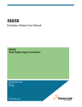
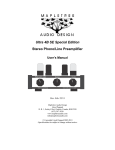
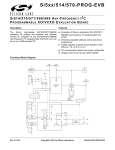
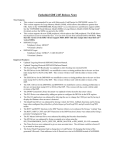
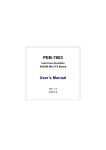
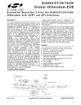
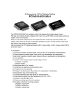
Telecommunications
Daughter Card #1
User Manual
56F800
16-bit Digital Signal Controllers
TDC1UM
Rev. 2
08/2005
freescale.com
TABLE OF CONTENTS
Preface
Chapter 1
Introduction
1.1
1.2
1.3
TDC1 Architecture . . . . . . . . . . . . . . . . . . . . . . . . . . . . . . . . . . . . . . . . . . 1-1
TDC1 Configuration Jumpers . . . . . . . . . . . . . . . . . . . . . . . . . . . . . . . . . . 1-3
TDC1 Connections . . . . . . . . . . . . . . . . . . . . . . . . . . . . . . . . . . . . . . . . . . 1-4
Chapter 2
Technical Summary
2.1
2.1.1
2.1.2
2.2
2.3
2.4
2.5
2.6
2.6.1
2.6.2
2.7
2.8
Audio Codec . . . . . . . . . . . . . . . . . . . . . . . . . . . . . . . . . . . . . . . . . . . . . . . 2-3
Codec Digital Data Path . . . . . . . . . . . . . . . . . . . . . . . . . . . . . . . . . . . 2-3
Codec Analog Data Path . . . . . . . . . . . . . . . . . . . . . . . . . . . . . . . . . . . 2-4
PSTN DAA . . . . . . . . . . . . . . . . . . . . . . . . . . . . . . . . . . . . . . . . . . . . . . . . 2-6
Clock Source . . . . . . . . . . . . . . . . . . . . . . . . . . . . . . . . . . . . . . . . . . . . . . 2-6
Keypad . . . . . . . . . . . . . . . . . . . . . . . . . . . . . . . . . . . . . . . . . . . . . . . . . . . 2-6
LCD . . . . . . . . . . . . . . . . . . . . . . . . . . . . . . . . . . . . . . . . . . . . . . . . . . . . . 2-8
Daughter Card Connectors. . . . . . . . . . . . . . . . . . . . . . . . . . . . . . . . . . . . 2-9
Memory Daughter Card Connector . . . . . . . . . . . . . . . . . . . . . . . . . . . 2-9
Peripheral Daughter Card Connector . . . . . . . . . . . . . . . . . . . . . . . . 2-11
Power Supply . . . . . . . . . . . . . . . . . . . . . . . . . . . . . . . . . . . . . . . . . . . . . 2-12
Test Points . . . . . . . . . . . . . . . . . . . . . . . . . . . . . . . . . . . . . . . . . . . . . . . 2-13
Appendix A
TDC1 Schematics
Appendix B
TDC1 Bill of Material
Appendix C
Keypad & LCD CPLD VHDL Code
Appendix D
Keypad & LCD CPLD Schematic
Table of Contents, Rev. 2
Freescale Semiconductor
i
TDC1 User Manual, Rev. 2
ii
Freescale Semiconductor
LIST OF FIGURES
1-1
Block Diagram of the TDC1. . . . . . . . . . . . . . . . . . . . . . . . . . . . . . . . . . . . . . 1-2
1-2
TDC1 Jumper Reference. . . . . . . . . . . . . . . . . . . . . . . . . . . . . . . . . . . . . . . .1-3
1-3
Connecting the TDC1 to an EVM . . . . . . . . . . . . . . . . . . . . . . . . . . . . . . . . . 1-4
2-1
Block Diagram of Audio Codec Digital Interface . . . . . . . . . . . . . . . . . . . . . . 2-3
2-2
Block Diagram of Microphone Input . . . . . . . . . . . . . . . . . . . . . . . . . . . . . . . 2-4
2-3
Block Diagram of Speaker Output . . . . . . . . . . . . . . . . . . . . . . . . . . . . . . . . . 2-5
2-4
Block Diagram of Line-Level Interface. . . . . . . . . . . . . . . . . . . . . . . . . . . . . . 2-5
2-5
DAA #1 Block Diagram . . . . . . . . . . . . . . . . . . . . . . . . . . . . . . . . . . . . . . . . . 2-6
2-6
Keypad Interface Block Diagram . . . . . . . . . . . . . . . . . . . . . . . . . . . . . . . . . .2-7
2-7
LCD Interface Block Diagram . . . . . . . . . . . . . . . . . . . . . . . . . . . . . . . . . . . . 2-8
2-8
Power Supply Block Diagram . . . . . . . . . . . . . . . . . . . . . . . . . . . . . . . . . . . 2-12
List of Figures, Rev. 2
Freescale Semiconductor
iii
TDC1 User Manual, Rev. 2
iv
Freescale Semiconductor
LIST OF TABLES
1-1
TDC1 Default Jumper Options . . . . . . . . . . . . . . . . . . . . . . . . . . . . . . . . . 1-4
2-1
SSI/ESSI Port Selector Description . . . . . . . . . . . . . . . . . . . . . . . . . . . . . 2-4
2-2
Keypad Row/Column Data Register. . . . . . . . . . . . . . . . . . . . . . . . . . . . . 2-7
2-3
LCD Data Register . . . . . . . . . . . . . . . . . . . . . . . . . . . . . . . . . . . . . . . . . . 2-8
2-4
LCD Control Register . . . . . . . . . . . . . . . . . . . . . . . . . . . . . . . . . . . . . . . .2-9
2-5
External Memory Daughter Card Connector Description . . . . . . . . . . . . . 2-9
2-6
Peripheral Daughter Card Connector Description . . . . . . . . . . . . . . . . . 2-11
List of Tables, Rev. 2
Freescale Semiconductor
v
TDC1 User Manual, Rev. 2
vi
Freescale Semiconductor
Preface
This reference manual describes in detail the hardware on the Telecommunication
Daughter Card #1 (TDC1).
Audience
This document is intended for application developers who are creating software for
devices using the Freescale TDC1 with a 56F826EVM, 56F827EVM, 56852EVM or
56858EVM.
Organization
This manual is organized into two chapters and two appendixes.
•
Chapter 1, Introduction provides an overview of the TDC1 and its features.
•
Chapter 2, Technical Summary describes in detail the TDC1 hardware.
•
Appendix A, TDC1 Schematics contains the schematics of the TDC1.
•
Appendix B, TDC1 Bill of Material provides a list of the materials used on the TDC1
board.
•
Appendix C, Keypad & LCD CPLD VHDL Code contains source code for
keypad and LCD.
•
Appendix D, Keypad & LCD CPLD Schematic includes a schematic of the
keypad and LCD.
Suggested Reading
More documentation on the 56F826EVM, 56F827EVM, 56852EVM and 56858EVM may
be found at URL:
www.freescale.com
Preface, Rev. 2
Freescale Semiconductor
vii
Notation Conventions
This manual uses the following notational conventions:
Term or Value
Symbol
Examples
Active High Signals
(Logic One)
No special symbol
attached to the signal
name
A0
CLKO
Active Low Signals
(Logic Zero)
Noted with an
overbar in text and in
most figures
WE
OE
Hexadecimal Values
Begin with a “$” symbol
$0FF0
$80
Decimal Values
No special symbol
attached to the
number
Binary Values
Begin with the letter
“b” attached to the
number
b1010
b0011
Numbers
Considered positive
unless specifically
noted as a negative
value
5
-10
Blue Text
Linkable on-line
Bold
Reference sources,
paths, emphasis
Exceptions
In schematic drawings, Active
Low Signals may be noted by
a backslash: /WE
10
34
Voltage is often shown as
positive: +3.3V
...refer to Chapter 7,
License
...see: www.freescale.com
TDC1 User Manual, Rev. 2
viii
Freescale Semiconductor
Definitions, Acronyms, and Abbreviations
Definitions, acronyms and abbreviations for terms used in this document are defined
below for reference.
AFE
Analog Front End; an interface used to refer to the high voltage or
PSTN side of a DAA
BOM
Bill of Material; list of parts used on the TDC1.
Codec
COder/DECoder; a part used to convert analog signals to digital
(coder) and digital signals to analog (decoder)
CPLD
Complex Programmable Logic Device
DAA
Data Access Arrangement; interface between telephone line and
codec
DSC
Digital Signal Controller
ESSI
Enhanced Synchronous Serial Interface port on Freescale’s family of
controllers
EVM
Evaluation Module; a hardware platform which allows a customer to
evaluate the silicon and develop his application
FCC
Federal Communications Commission
GPIO
General Purpose Input and Output port on Freescale’s family of
controllers; does not share pin functionality with any other peripheral
on the chip and can only be set as an input, output or level-sensitive
interrupt input
IC
Integrated Circuit
JTAG
Joint Test Action Group; a bus protocol/interface used for test and
debug
LED
Light Emitting Diode
MPIO
Multi Purpose Input and Output port on Freescale’s family of
controllers; shares package pins with other peripherals on the chip
and can function as a GPIO
PCB
Printed Circuit Board
PSTN
Public Service Telephone Network
SSI
Synchronous Serial Interface port on Freescale’s family of controllers
Preface, Rev. 2
Freescale Semiconductor
ix
References
The following sources were referenced to produce this manual:
[1] 56F826 Evaluation Module User Manual, DSP56826EVMUM
[2] 56F827 Evaluation ModuleUser Manual, DSP56827EVMUM
[3] 56852 Evaluation Module User Manual, DSP56852EVMUM
[4] 56858 Evaluation Module User Manual, DSP56858EVMUM
TDC1 User Manual, Rev. 2
x
Freescale Semiconductor
Chapter 1
Introduction
The TDC1, in combination with the 56F826EVM, 56F827EVM, 56852EVM or
56858EVM, can be used to demonstrate the abilities of the 56F826, 56F827, 56852 or
56858 processor in PSTN applications and provide a hardware tool allowing the
development of applications that use these processors.
The TDC1 is a daughter card that includes two global solid state DAA interfaces, a voice
codec, 5x5 push-button keypad, a 20x4 LCD display and a set of daughter card
expansion connectors. The daughter card expansion connectors allow the daughter
card to communicate with the attached EVM.
The TDC1, along with the attached EVM, is designed for the following purposes:
•
Serves as a platform for real-time software development. The TDC1 daughter
card and EVM tool suite enable the user to develop and simulate routines,
download the software to on-chip or on-board RAM, run it, and debug it using a
debugger via the JTAG/OnCE/Enhanced OnCE (EOnCE) port or the on-board
Parallel Host/Target Interface. The breakpoint features of the OnCE/EOnCE port
enable the user to easily specify complex break conditions and to execute
user-developed software at full speed until the break conditions are satisfied. The
ability to examine and modify all user-accessible registers, memory and
peripherals through the OnCE/EOnCE port greatly facilitates the task of the
developer.
•
Serving as a platform for hardware development. The hardware platform enables
the user to connect external hardware peripherals. The on-board peripherals can
be disabled, providing the user with the ability to reassign any and all of the
controller's peripherals. The OnCE/EOnCE port's unobtrusive design means that
all memory on the board and on the chip is available to the user.
Introduction, Rev. 2
Freescale Semiconductor
1-1
1.1 TDC1 Architecture
The TDC1 facilitates the development of various voice and data telephony applications.
The TDC1 block diagram, in Figure 1-1, shows the major blocks of this daughter card.
High Voltage PSTN
SSI/ESSI
GPIO/MPIO
DAA Codec
#1
DAA Interface
#1
RJ11
#1
GPIO/MPIO
DAA Codec
#2
DAA Interface
#2
RJ11
#2
GPIO/MPIO
Telephony
Codec
Microphone In
Speaker Out
Daughter Card
Peripheral Connector
Memory Bus
Memory
Mapped
Registers
20 x 4
LCD
5x5
Keypad
Daughter Card
Memory Connector
Figure 1-1. Block Diagram of the TDC1
The main features of the TDC1 daughter card include the following:
•
Dual PSTN Solid State DAA Interface
— Two separate and unique telephone interfaces
— PSTN High Voltage Isolation
— Ring Detection
— ON-Hook/OFF-Hook Support
— Caller ID Support
— Communicates with the controller over SSI/ESSI bus
TDC1 User Manual, Rev. 2
1-2
Freescale Semiconductor TDC1 Architecture
•
Voice Codec
— Microphone Input
— Microphone Bias Option
— Dual channel Speaker Output
— Line Level Input/Output
— Communicates with the controller over SSI/ESSI bus
•
5 row by 5 column push-button (keypad) matrix
•
20 character by 4 line LCD display
•
Daughter Card Peripheral Expansion Interface connector
— SSI/ESSI signals
— GPIO/MPIO signals
— +3.3V and +5.0V Power (on 56852EVM and 56858EVM)
— Ground
•
Daughter Card Memory Expansion Interface connector
— External Data Bus
— External Address Bus
— External Data/Address Bus control signals
— +3.3V and +5.0V Power (on 56852EVM and 56858EVM)
— Ground
•
+5.0V Power Terminal block (Optional +5.0V power source)
Introduction, Rev. 2
Freescale Semiconductor
1-3
1.2 TDC1 Configuration Jumpers
Six jumper groups, (JG1-JG6), shown in Figure 1-2, are used to configure various
features on the TDC1. Table 1-1 describes the default jumper group settings.
1
3
JG2
JG3
JG1
1
TB1
+5V
Mic
IN
J2
J1
JG5
Speaker
OUT
GND
3
JG2
J3
JG6
LCD
J4
PSTN #1
JG6
JG3
16
JG1
18
JG4
JG5
J104
PSTN #2
JG4
Figure 1-2. TDC1 Jumper Reference
TDC1 User Manual, Rev. 2
1-4
Freescale Semiconductor TDC1 Configuration Jumpers
Table 1-1. TDC1 Default Jumper Options
Jumper
Group
Note:
Comment
Jumpers
Connections
JG1
Selects the use of SSI1/ESSI1 Port signals for the Codecs
2–3, 5–6, 8–9, 11–12,
14–15, 17–18
JG2
Use of the on-board microphone bias voltage
1–2
JG3
Uses Frame Sync from DAA #2 Codec for Voice Codec
2–3
JG4
Enables DAA #2 Codec
1–2
JG5
Uses the +5.0V power from the EVM
1–2
JG6
Uses CS3 to enable the CPLD’s Keypad and LCD registers
1–2
When using the TDC1 board with a 56F826EVM, 56F827EVM, 56852EVM or
56858EVM board, with Processor Expert, the jumper configurations for the
TDC1 board must be changed as follows:
•
JG1 must have the jumpers configured to use SC0 instead of SC1. The jumper
settings need to be changed to 1-2, 4-5, 7-8, 10-11, 13-14, 16-17.
•
JG3 must be configured for Codec Frame Sync 1 instead of Codec Frame Sync 2.
The jumper setting need to be changed to 1-2.
•
JG4 must changed to disable DAA 2. The jumper on JG4 must be removed.
This is due to a limitation in the Processor Expert only supporting the first channel of the
two channel TDC1 board.
The TDC1 attaches to a 56F826EVM, 56F827EVM, 56852EVM or 56858EVM via the
two Daughter Card connectors located on the bottom of the TDC1 handle. An
interconnection diagram is shown in Figure 1-3 for connecting the TDC1 onto the top of
an EVM board.
Note:
If using a 56852EVM or 56858EVM board, the +5.0V used to power the LCD
module can be supplied by the EVM by installing jumper JG5. If a 56F826EVM
or 56F827EVM board is being used, the +5.0V for the LCD module should be
supplied to the TDC1 Daughter Card at TB1 by an external +5.0V DC power
supply.
Introduction, Rev. 2
Freescale Semiconductor
1-5
TDC1 Board
EVM Board
Daughter Card
Connectors
Figure 1-3. Connecting the TDC1 to an EVM
Perform the following steps to connect the TDC1 to an EVM:
1. Align the two daughter card connectors of the bottom on the TDC1 board with the
two daughter card connectors on the top of the EVM board
2. Firmly press the two boards together at these connectors to attach
3. Following the power connection instructions in User’s Manual for the EVM you’re
implementing, connect power to the EVM
4. If +5.0V power is to be provided for the LCD from an external +5.0V power supply:
— Remove the jumper at JG5
— Attach the +5.0V power to the TDC1 at TB1
Note:
Failure to remove JG5 could potentially damage the EVM
5. Apply power to the EVM.
— The TDC1’s green Power-On LED, LED1, will illuminate when +3.3V power is
present
TDC1 User Manual, Rev. 2
1-6
Freescale Semiconductor Chapter 2
Technical Summary
The TDC1, in combination with the 56F826EVM, 56F827EVM, 56852EVM or
56858EVM, can be used to demonstrate the abilities of the 56F826, 56F827, 56852 or
56858 processor in PSTN applications and provide a hardware tool allowing the
development of applications that use these processors.
The TDC1 is a daughter card that includes two global solid state DAA interfaces, a
telecommunications codec, 5x5 push-button keypad, a 20x4 LCD display and a set of
daughter card expansion connectors. The daughter card expansion connectors allow
the daughter card to communicate with the attached EVM.
The main features of the TDC1 Daughter Card, with board and schematic reference
designators, include:
•
PSTN Solid State DAA Interface #1 (U2 & U3)
— RJ11 Telephone interfaces (J4)
— PSTN High Voltage Isolation Interface (U3)
— Ring Detection (U2)
— ON-Hook/OFF-Hook Support (U2)
— Caller ID Support (U2)
— Communicates with the controller over SSI/ESSI bus (U2)
•
PSTN Solid State DAA Interface #2 (U102 & U103)
— RJ11 Telephone interfaces (J104)
— PSTN High Voltage Isolation Interface (U103)
— Ring Detection (U102)
— ON-Hook/OFF-Hook Support (U102)
— Caller ID Support (U102)
— Communicates with the controller over SSI/ESSI bus (U102)
Technical Summary, Rev. 2
Freescale Semiconductor
2-1
•
Voice Codec (U1)
— Microphone Input (J1)
— Microphone Bias Option (JG2)
— Dual-channel Speaker Output (J2)
— Line-Level Input/Output (J3)
— Communicates with the controller over SSI/ESSI bus (U1)
•
5 Row by 5 Column push-button (keypad) matrix (S1-S25)
•
20 character by 4 line LCD display (LCD1)
•
LCD contrast adjustment (R49)
•
Keypad & LCD memory bus register logic (U5)
•
Optional CS3 enable (JG6)
•
Optional +5.0V supplied from 56852EVM or 56858EVM board (JG5)
•
SSI/ESSI Port 0 or Port 1 source selector (JG1)
•
DAA #2 selector (JG4)
•
Audio Codec Frame Sync source selector (JG3)
•
Daughter Card Peripheral Expansion Interface connector (P2)
— SSI/ESSI signals
— GPIO/MPIO signals
— +3.3V and +5.0V Power (on 56852EVM and 56858EVM)
— Ground
•
Daughter Card Memory Expansion Interface connector (P1)
— External Data Bus
— External Address Bus
— External Data/Address Bus control signals
— +3.3V and +5.0V Power (on 56852EVM and 56858EVM)
— Ground
•
+5.0V Power Terminal block. (Optional +5.0V power source) (TB1)
•
+3.3V Power OK LED (LED1)
TDC1 User Manual, Rev. 2
2-2
Freescale Semiconductor Audio Codec
2.1 Audio Codec
The TDC1 uses a Silicon Labs Si3000, designated as U1 on the board and in the
schematics. This Codec provides the Microphone Input analog to digital and digital to
analog Speaker Output interface for the EVM’s controller.
2.1.1 Codec Digital Data Path
The Audio Codec is connected to the SSI/ESSI signals from the Peripheral Daughter
Card connector through the SSI/ESSI Port selector, JG1. SSI0/ESSI0 and SSI1/ESSI1
Port signals are present on JG1, allowing the easy use of either port. To select
SSI0/ESSI0 port, jumper the left pins of the header to the header’s center pins. To select
SSI1/ESSI1 port, jumper the right pins of the header to the header’s center pins;
reference Figure 2-1 and Table 2-1.
Si3000
P2
JG1
STD
SSI0/ESSI0
SDI
SRD
SDO
SCK
SSI1/ESSI1
MCLK
SCx1
Peripheral
Daughter Card
RESET
JG3
FSDAA1
1
FSDAA2
3
FSYNC
Figure 2-1. Block Diagram of Audio Codec Digital Interface
Technical Summary, Rev. 2
Freescale Semiconductor
2-3
Table 2-1. SSI/ESSI Port Selector Description
JG1
Pin #
Signal
Pin #
Signal
Pin #
Signal
1
STD0
2
SDI
3
STD1
4
SRD0
5
SDO
6
SRD1
7
SCK0
8
SCLK
9
SCK1
10
SC00
11
DAARST
12
SC10
13
SC01
14
RST
15
SC11
16
SC02
17
MFSYNC
18
SC12
.
2.1.2 Codec Analog Data Path
The CODEC provides microphone input, speaker output, line-level input and line-level
output analog paths.
2.1.2.1 Microphone Input
The microphone input is via a 1/8” stereo phone jack (J1); reference Figure 2-2. The tip
connection on the jack provides the mono microphone input signal. The ring connection
on the jack provides an optional microphone bias voltage for use with Electret
condenser microphones. The barrel connection on the jack provides the microphone
ground reference signal.
MIC_BIAS
Microphone Bias
Microphone
Input
MIC_IN
A
Figure 2-2. Block Diagram of Microphone Input
TDC1 User Manual, Rev. 2
2-4
Freescale Semiconductor Audio Codec
2.1.2.2 Speaker Output
The speaker output is provided via another 1/8” stereo phone jack (J2); reference
Figure 2-3. The tip connection on the jack provides the Left speaker channel output
signal. The ring connection on the jack provides the Right speaker channel output
signal. The barrel connection on the jack provides the speaker’s ground reference
signal.
SPKR_R
Speaker
Output
SPKR_L
A
Figure 2-3. Block Diagram of Speaker Output
2.1.2.3 Line-Level Analog
The line-level input and output signals are provided via a 3-pin header (J3); reference
Figure 2-4. This header allows easy connection to the line-level output, on pin-1,
line-level input, on pin-2, and ground reference signals, on pin-3.
Line_Out
1
Line_In
2
Line Level
Input/Output
3
A
Figure 2-4. Block Diagram of Line-Level Interface
Technical Summary, Rev. 2
Freescale Semiconductor
2-5
2.2 PSTN DAA
Two PSTN DAAs are used on the TDC1 to provide the high-voltage telephone line
isolation, proper AC and DC telephone line load terminations, On/Off Hook control, Ring
Detection and Caller ID support for two separate PSTN lines.
Each PSTN DAA, Silicon Labs Si3044 chipset, on the TDC1 supports a single telephone
line in various data modem and fax standards, i.e., V.22bis, V.8bis, V.32bis, V.42bis,
V.34bis, V.17, V.21, V.27, V.29 and V.90. The chipset consists of an Analog Front End
(AFE) part, Silicon Labs Si3015, which interfaces to the high voltage PSTN and a Digital
Interface part, Silicon Labs Si3021, which interfaces with the controller and Codec. See
Figure 2-5 for a block diagram of the DAA #0 DAA. The Si3015 and Si3021 parts are
capacitively coupled, providing over 3000 volts of isolation between the PSTN and the
on-board digital electronics.
U2
U3
J4
TIP
C1
AFE
DAA CODEC
RING
RJ11
Peripheral
Daughter Card
Figure 2-5. DAA #1 Block Diagram
2.3 Clock Source
The Master Clock Source for the TDC1 is a 4.000MHz oscillator. This Master Clock
Source is used to drive the Master DAA Codec. Using its on-chip PLL, it can create the
required bit rates for various telecommunication protocols.
TDC1 User Manual, Rev. 2
2-6
Freescale Semiconductor Keypad
2.4 Keypad
The TDC1 provides a 5 x 5 push-button keypad (S1-S25). These push-buttons are
unlabeled and arranged in a 5 row by 5 column matrix. This keypad matrix is connected
to the controller as memory-mapped GPIO via a CPLD (U5). This CPLD connects to the
controller’s address and memory bus providing I/O for row-strobing and column-sensing
keypad detection to the keypad via a memory-mapped register; reference Figure 2-6
and Table 2-2. The CPLD is configured to use CS3 as the chip select for the
memory-mapped registers. The Keypad will be assigned to the first address location in
this CS3 enabled memory map. CS3 can be disabled from the TDC1 to allow other uses
for this chip select by removing the jumper on JG6. This location contains the 5-bit Row
write register and the 5-bit Column read register. This allows the code developer to
strobe the rows and sense the columns.
U5
J1
Row0-4
Address
Keypad/LCD
CPLD
Data
5x5
Keypad
Matrix
Control
CS3
CS
Column0-4
JG6
Daughter Card
Memory Connector
Figure 2-6. Keypad Interface Block Diagram
Table 2-2. Keypad Row/Column Data Register
CS3 Base Address + 0
Bit #
Write Function
Read Function
0
Row 0 Strobe
Column 0 State
1
Row 1 Strobe
Column 1 State
2
Row 2 Strobe
Column 2 State
3
Row 3 Strobe
Column 3 State
4
Row 4 Strobe
Column 4 State
Technical Summary, Rev. 2
Freescale Semiconductor
2-7
2.5 LCD
The TDC1 provides a 20 character by 4 line LCD display. This display has a parallel
interface, allowing the LCD to be connected to a memory-mapped GPIO CPLD. This
CPLD is connected to the controller’s memory bus providing I/O to the LCD via a
memory-mapped register; reference Figure 2-7. The CPLD is configured to use CS3 as
the chip select for the memory-mapped registers. CS3 can be disabled from the TDC1 to
allow other uses for this chip select by removing the jumper on JG6. The LCD is
assigned to the second and third address locations in the CS3-enabled memory map.
The first LCD address location contains the 8-bit read/write LCD Data register; reference
Table 2-3. The second LCD address location contains the 3-bit read/write LCD Control
register; reference Table 2-4.
U5
J1
Address
Data0-7
Keypad/LCD
CPLD
Data
RS, RW, E
20 x 4
LCD
Control
CS3
CS
JG6
Daughter Card
Memory Connector
Figure 2-7. LCD Interface Block Diagram
TDC1 User Manual, Rev. 2
2-8
Freescale Semiconductor LCD
Table 2-3. LCD Data Register
CS3 Base Address + 1
Bit #
LCD Function
0
Data bit 0 to/from LCD
1
Data bit 1 to/from LCD
2
Data bit 2 to/from LCD
3
Data bit 3 to/from LCD
4
Data bit 4 to/from LCD
5
Data bit 5 to/from LCD
6
Data bit 6 to/from LCD
7
Data bit 7 to/from LCD
Table 2-4. LCD Control Register
CS3 Base Address + 2
Bit #
Symbol
LCD Function
0
RS
1 = Data Input to LCD; 0 = Instruction Code Input to LCD
1
R/W
1 = Read Data from LCD; 0 = Write Data to LCD
2
E
Normally 1; Transition from 1 => 0 Enables Transfer
Technical Summary, Rev. 2
Freescale Semiconductor
2-9
2.6 Daughter Card Connectors
Two Daughter Card connectors are provided on the TDC1 Daughter Card. One
Daughter Card connector provides access to the controller’s peripherals. The other
Daughter Card connector provides access to the controller’s external memory bus.
2.6.1 Memory Daughter Card Connector
An External Memory Daughter Card connector provides all of the controller’s address,
data and external memory interface control signals, along with power and ground. Only
the controller signals used by the TDC1 are present on the connector; reference
Table 2-5.
Table 2-5. External Memory Daughter Card Connector Description
P1
Pin #
Signal
Pin #
Signal
1
NC
2
NC
3
NC
4
NC
5
NC
6
NC
7
NC
8
NC
9
NC
10
NC
11
WR
12
NC
13
D0
14
NC
15
D1
16
NC
17
D2
18
NC
19
GND
20
GND
21
D3
22
NC
23
D4
24
NC
25
D5
26
NC
27
D6
28
NC
29
NC
30
NC
31
D7
32
NC
TDC1 User Manual, Rev. 2
2-10
Freescale Semiconductor Daughter Card Connectors
Table 2-5. External Memory Daughter Card Connector Description (Continued)
P1
Pin #
Signal
Pin #
Signal
33
NC
34
NC
35
A0
36
RD
37
A1
38
NC
39
NC
40
GND
41
NC
42
NC
43
NC
44
NC
45
CS3
46
NC
47
+3.3V
48
+3.3V
49
GND
50
GND
51
+5.0V
2.6.2 Peripheral Daughter Card Connector
The peripheral daughter card connector provides the SSI/ESSI and GPIO signals from
the controller, along with power and ground for the TDC1. Only the signals used on the
TDC1 are used on this connector; reference Table 2-6.
Table 2-6. Peripheral Daughter Card Connector Description
P2
Pin #
Signal
Pin #
Signal
1
NC
2
NC
3
NC
4
NC
5
NC
6
NC
7
NC
8
NC
9
NC
10
NC
11
NC
12
NC
13
GND
14
GND
Technical Summary, Rev. 2
Freescale Semiconductor
2-11
Table 2-6. Peripheral Daughter Card Connector Description (Continued)
P2
Pin #
Signal
Pin #
Signal
15
SRD0
16
SRD1
17
SC01
18
SC11
19
NC
20
SCK1
21
GND
22
GND
23
NC
24
SC10
25
NC
26
SC12
27
GND
28
GND
29
NC
30
STD1
31
SC00
32
NC
33
SC02
34
NC
35
NC
36
NC
37
GND
38
GND
39
STD0
40
NC
41
SCK0
42
NC
43
NC
44
NC
45
NC
46
NC
47
+3.3V
48
+3.3V
49
GND
50
GND
51
+5.0V
TDC1 User Manual, Rev. 2
2-12
Freescale Semiconductor Power Supply
2.7 Power Supply
The main power, +3.3VDC, for the TDC1 is provided through the Daughter card
connectors; reference Figure 2-8. This power will be used by most of the components
on the TDC1 board. The secondary power, +5.0V DC, for use by the LCD is provided
through the Daughter Card connectors and, optionally, via a terminal block on the TDC1
board. The analog voltages required by the analog logic on the TDC1 board are to be
created from the +3.3V digital supply.
A Power-On LED illuminates when +3.3V power is provided on the TDC1 board.
Technical Summary, Rev. 2
Freescale Semiconductor
2-13
Daughter Card Connectors
+5.0VDC
+5.0VDC
Power
Condition
+3.3V DC
Analog
+3.3V DC
Power Selector
1
2
+3.3V DC
+5.0V DC
+5.0VDC 1
GND
2
Terminal
Block
Codec
Codec
CPLD
LCD
Figure 2-8. Power Supply Block Diagram
2.8 Test Points
Test points are provided on the TDC1 board to allow voltage and signal reference
measurements for the following test points:
•
•
•
•
•
•
•
•
•
•
•
Codec AOUT
DAA #1 AOUT
DAA #1 RGDT
DAA #1 OFHK,
DAA #1 +3.3VA
DAA #2 AOUT
DAA #2 RGDT
DAA #2 OFHK
+3.3V
+5.0V
GND
TDC1 User Manual, Rev. 2
2-14
Freescale Semiconductor Appendix A
TDC1 Schematics
Appendix A, Rev. 2
Freescale Semiconductor
A-1
TDC1 User Manual, Rev. 2
A-2
Freescale Semiconductor 1
2
3
4
A
A
Daughter Card
Memory Connector
A
Size
Title
LCD
5 x 5
Keypad
Matrix
TDC1.DSN
C
Date: Monday, May 20, 2002
Document
Number
D
D
PSTN LINE 2
PSTN LINE 1
E
E
of
9
1.2
Rev.
FAX: (480) 413-2510
Sheet 1
(480) 413-5090
2100 East Elliot Road
Tempe, Arizona 85284
DSP Standard Products Division
RJ11
RJ11
Designer: D S P D D e s i g n
DAA
HIGH-SIDE
DAA
HIGH-SIDE
TDC1 BLOCK DIAGRAM OVERVIEW
Memory
Mapped
I/O
Registers
CODEC
FS
DAA
LOW-SIDE
FS
DAA
LOW-SIDE
C
Figure A-1. TDC1 BLOCK DIAGRAM OVERVIEW
B
Control
Data
Address
Daughter Card
Peripheral Connector
SSI/ISSI/ESSI
B
1
2
3
4
Appendix A, Rev. 2
Freescale Semiconductor
A-3
1
2
3
4
5.50"
2.5"
J4
A
TB1
4"
HIGH VOLTAGE AREA
HIGH VOLTAGE AREA
J104
A
U103
U3
J1
B
U102
U2
U1
J2
B
8"
TDC1.DSN
C
Date: Monday, May 20, 2002
Document
Number
TDC1 PART PLACEMENT
P2
D
4.15"
D
U5
E
1.5"
E
of
9
1.2
Rev.
FAX: (480) 413-2510
Sheet 2
(480) 413-5090
2100 East Elliot Road
Tempe, Arizona 85284
DSP Standard Products Division
P1 & P2 on bottom of board.
Designer: D S P D D e s i g n
NOTE:
S/N
TELECOMMUNICATIONS
DAUGHTER CARD
COPYRIGHT @ 2002
MOTOROLA, INC
Figure A-2. TDC1 PART PLACEMENT
A
Size
Title
S25
S21
S5
S15
20 X 4 LCD
S11
S1
P3
3.875"
C
P1
1
2
3
4
TDC1 User Manual, Rev. 2
1
2
3
4
R4
47K
12
13
14
JG3 OPTIONS
+3.3V
+3.3VA1
4
5
7
9
6
VD
VA
GND
SDI
SDO
MCLK
Si3000-KS
RESET
FSYNC
U1
HDST
SPKRL
SPKRR
LINE0
LINE1
MIC
MBIAS
SCLK
A
A
Size
1 T P 10
TDC1.DSN
C
Date: Monday, May 20, 2002
Document
Number
C36
10uF
30
R20
0.1uF
C34
2.2K
D
1
2
3
J3
3
11
10
2
1
3
11
10
2
1
J2
E
J1
E
of
9
1.2
Rev.
FAX: (480) 413-2510
Sheet 3
(480) 413-5090
2100 East Elliot Road
Tempe, Arizona 85284
DSP Standard Products Division
30
R21
C38
0.1uF
C37
10uF
C33
0.1uF
R14
Designer: D S P D D e s i g n
LINE_IN
D
C35
10uF
LINE_OUT
SPKR_L
MIC_IN
2
JG2
1
SPKR_R
MIC_BIAS
CODEC AND AUDIO CONNECTIONS
AOUT
SPKR_L
SPKR_R
16
1
3
LINE_OUT
LINE_IN
MIC_IN
MIC_BIAS
15
11
2
10
8
47K
R1
+3.3V
C
Figure A-3. CODEC AND AUDIO CONNECTIONS
B
CODEC DISABLED
N/C
Title
CODEC IN SSI CHAIN AFTER DAA #2
2-3
1-2
SDI
SDO
SCLK
2
CODEC IN SSI CHAIN AFTER DAA #1
3
FSD2
/RST
1
JG3
FSD1
B
+
+
A
+
A-4
Freescale Semiconductor 1
2
3
4
Appendix A, Rev. 2
1
2
3
15
16
18
SC11
SC02
SC12
17
14
11
8
5
2
A
SSI Signal Selector
13
SC01
10
SC00
12
9
SCK1
SC10
7
SCK0
4
SRD0
6
3
STD1
SRD1
1
STD0
JG1
+3.3V
2
1
4
B
U4
OUT
4.000MHz
GND
EN
VCC
A
Size
Title
3
/DAARST
SCLK
C41
0.1uF
VA
C42
0.1uF
GND
M0
M1
VD
12
14
10
4
13
9
11
16
7
M0
M1
10
TDC1.DSN
C
Date: Monday, May 20, 2002
Document
Number
1 T P 13
DAACOUPLING1
1 TP2
1 TP1
D
1K
R23
1K
R22
10K
R38
10K
R37
+3.3V
Sheet 4
E
of
9
1.2
Rev.
FAX: (480) 413-2510
2100 East Elliot Road
Tempe, Arizona 85284
(480) 413-5090
Designer: D S P D D e s i g n
D
M1
M0
/OFHK
/RGDT
E
DSP Standard Products Division
+3.3VA1
MASTER MODE
+3.3V
+3.3VA1
C39
0.1uF
AOUT
/OFHK
/RGDT
TP7
R3
Si3021KS
RGDT/FSD
RESET
SCLK
AOUT
C1A
DEHK
FC/RGDT
TP3
15
8
3
SDO
SDI
FSYNC
MCLK
U2
D A A L O W V O LTAGE SECTION CHANNEL #1
+3.3V
FSD1
6
SDI
5
2
/MFSYNC
SDO
1
MCLK
C
Figure A-4. DAA LOW VOLTAGE SECTION CHANNEL #1
/MFSYNC
/RST
/DAARST
SCLK
SDO
SDI
10K
R27
+3.3V
B
1
4
A
1
Freescale Semiconductor
A-5
1
2
3
4
TDC1 User Manual, Rev. 2
A-6
Freescale Semiconductor 1
2
3
4
A
A
FSD1
2
DAA #2
ENABLE
1
JG4
B
C141
0.1uF
C142
0.1uF
12
14
10
4
13
9
11
16
7
C139
0.1uF
M0
M1
AOUT
/OFHK
/RGDT
+3.3VA2
SLAVE MODE
+3.3V
+3.3VA2
1 T P 14
DAACOUPLING2
1 TP9
1 TP8
TDC1.DSN
C
Date: Monday, May 20, 2002
Document
Number
D
D
SDO
M0
M1
/FSYNC
/OFHK
/RGDT
47K
R144
1K
R122
1K
R123
10K
R141
10K
R138
10K
R137
+3.3V
E
E
of
9
1.2
Rev.
FAX: (480) 413-2510
Sheet 5
(480) 413-5090
2100 East Elliot Road
Tempe, Arizona 85284
DSP Standard Products Division
Designer: D S P D D e s i g n
D A A L O W V O LTAGE SECTION CHANNEL #2
10
R103
GND
M0
M1
VD
VA
AOUT
C1A
DEHK
FC/RGDT
Si3021KS
RGDT/FSD
RESET
SCLK
SDO
SDI
FSYNC
Size
A
U102
MCLK
Title
15
8
3
5
6
2
1
C
Figure A-5. DAA LOW VOLTAGE SECTION CHANNEL #2
+3.3V
FSD2
/DAARST
SDO
SDI
/FSYNC
SCLK
B
1
2
3
4
Freescale Semiconductor
1
2
3
4
D A A C O U P L I N G1
R7
4.87K
1%
A
1 5 0pF
C1
R8
4.87K
1%
A
R15
4.87K
1%
U3
B
C
E
B
E
C14
0.68uF
R11
10K
1%
R12
78.7
1%
R13
215
1%
C8
C7
Anode
R18
2.2K
15K
R9
15K
R10
C22
1800pF
Cathode
Common
CMPD2004S
1 8 00pF
C18
0.012uF
C19
0.012uF
1 8 00pF
R2
402
1%
0.1uF
C5
C
C
Q4
Z1
ZMM43
R24
150
BCP56T1
R16
4.87K
1%
Q3
R19
4.87K
1%
B
Size
Title
C9
D2
D1
C4
1 5 0pF
R25
10M
R26
10M
FB2
FB1
TDC1.DSN
D
Date: Monday, May 20, 2002
Document
Number
C31
1000pF
TIP
RING
C32
1000pF
E
RJ11
6
5
4
3
2
1
J4
Designer: DSPD Design
E
of
9
1.2
Rev.
FAX: (480) 413-2510
Sheet 6
(480) 413-5090
2100 East Elliot Road
Tempe, Arizona 85284
DSP Standard Products Division
SID1
P3100SB
BLM31A601S
C24
1000pF
C25
1000pF
BLM31A601S
G L OBAL DAA High Voltage Section Channel #1
CMPD2004S
0.01uF
C20
120K
R6
MMBTA92LT1
0.022uF
CMPD2004S
Q2
MMBTA42LT1
MMBTA42LT1
R17
4.87K
1%
R5
100K
1%
Q1
D
Figure A-6. GLOBAL DAA HIGH VOLTAGE SECTION CHANNEL #1
B
C12
1.0uF
C16
0.1uF
C
C6
0.1uF
C
16
15
14
13
12
11
10
9
MMBTA42LT1
MMBTA92LT1
Si3015-KS
TSTA/QE2
TX/FILT2
TSTB/DCT
NC/FILT
IGND
RX
C1B
REXT
RNG1
DCT/REXT2
RNG2
NC/REF
QB
NC/VREG2
QE
VREG
BCP56T1
1
2
3
4
5
6
7
8
C13 +
0.1uF
B
+
Appendix A, Rev. 2
A-7
1
2
3
4
A-8
1
2
3
4
D A A C O U P L I N G2
R 1 07
4.87K
1%
R 1 08
4.87K
1%
A
1 5 0pF
C 1 01
A
R 1 15
4.87K
1%
C 1 16
0.1uF
B
C
E
E
C 1 14
0.68uF
R 1 11
10K
1%
R 1 13
215
1%
R 1 12
78.7
1%
C 1 05
C 1 08
C 1 07
Anode
15K
R 1 09
15K
R 1 10
Cathode
Common
R 1 18
C
2.2K
C 1 22
1 8 00pF
CMPD2004S
1 8 00pF
C 1 18
0.012uF
C 1 19
0.012uF
1 8 00pF
R102
402
1%
0.1uF
C
Q104
Z 1 01
ZMM43
R124
150
BCP56T1
B
Size
Title
R 1 16
4.87K
1%
Q103
R 1 19
4.87K
1%
C 1 09
D 1 02
C 1 04
150pF
R 1 25
10M
R 1 26
10M
TDC1.DSN
D
Date: Monday, May 20, 2002
Document
Number
F B 102
F B 101
S I D 1 01
P3100SB
E
C 1 31
1 0 00pF
C 1 32
1 0 00pF
TIP
RING
RJ11
6
5
4
3
2
1
J 1 04
Designer: DSPD Design
E
of
9
1.2
Rev.
FAX: (480) 413-2510
Sheet 7
(480) 413-5090
2100 East Elliot Road
Tempe, Arizona 85284
DSP Standard Products Division
BLM31A601S
C 1 24
1000pF
C 1 25
1000pF
BLM31A601S
G L OBAL DAA High Voltage Section Channel #2
CMPD2004S
D 1 01
0.022uF
CMPD2004S
0.01uF
C 1 20
120K
R 1 06
MMBTA92LT1
Q102
MMBTA42LT1
MMBTA42LT1
R 1 17
4.87K
1%
R 1 05
100K
1%
Q101
D
Figure A-7. GLOBAL DAA HIGH VOLTAGE SECTION CHANNEL #2
B
B
C
C 1 06
0.1uF
C
16
15
14
13
12
11
10
9
MMBTA42LT1
MMBTA92LT1
Si3015-KS
TSTA/QE2
TX/FILT2
TSTB/DCT
NC/FILT
IGND
RX
C1B
REXT
RNG1
DCT/REXT2
RNG2
NC/REF
QB
NC/VREG2
QE
VREG
C 1 12
1.0uF
BCP56T1
1
2
3
4
5
6
7
8
U 1 03
C 1 13 +
0.1uF
B
+
TDC1 User Manual, Rev. 2
Freescale Semiconductor 1
2
3
4
Appendix A, Rev. 2
Freescale Semiconductor
A-9
1
2
3
4
LCD
CONTRAST
ADJUST
1
2
3
4
5
6
R49
10K
A
+5.0V
15
26
35
9
24
11
10
1
2
3
5
6
7
8
12
13
14
16
18
19
VO
GND
TCK
TDO
TDI
TMS
+3.3V
TDI
TDO
TCK
TMS
XILINX JTAG
J6
+3.3V
D0
D1
D2
D3
D4
D5
D6
D7
A0
A1
/RD
/WR
/CS3
A
U5
GND1
GND2
GND3
IO14
IO15
IO16
IO17
IO18
IO19
IO20
IO21
IO22
IO23
GSR/IO24
IO25
GTS/IO26
IO27
IO28
IO29
IO30
IO31
IO32
GCK2/IO33
GCK3/IO34
P3
1
2
3
4
5
6
7
8
9
10
11
12
13
14
15
16
LCD
DD7
DD6
DD5
DD4
DD3
DD2
DD1
DD0
/E
R/W
RS
ROW0
COL0
ROW1
COL1
ROW2
COL2
ROW3
COL3
ROW4
COL4
B
1 T P 11
1 T P 12
+5.0V
4
17
25
20
21
22
23
27
28
29
30
31
32
33
34
36
37
38
39
40
41
42
43
44
A
Size
Title
ROW2
ROW1
ROW0
1K
+3.3V
TDC1.DSN
C
Date: Tuesday, May 21, 2002
Document
Number
COL4
COL3
COL2
COL1
COL2
S23
S18
S13
S8
S3
D
+3.3V
D
COL3
S24
S19
S14
S9
S4
/CS3
R/W
RS
/E
S25
S20
S15
S10
S5
47K
R146
47K
R62
47K
R61
47K
R60
COL4
E
+3.3V
E
of
9
1.2
Rev.
FAX: (480) 413-2510
Sheet 8
(480) 413-5090
2100 East Elliot Road
Tempe, Arizona 85284
DSP Standard Products Division
1K
R59
1K
R58
1K
R57
1K
R56
Designer: D S P D D e s i g n
5 X 5 KEYPAD MATRIX AND LCD DISPLAY
47K
R55
COL0
R54
47K
R53
R52
ROW4
ROW3
S22
S17
S12
S7
S2
COL1
47K
+3.3V
COL0
S21
S16
S11
S6
47K
R51
47K
R50
ROW4
ROW3
ROW2
ROW1
ROW0
S1
C
Figure A-8. 5 X 5 KEYPAD MATRIX AND LCD DISPLAY
VO
RS
R/W
/E
DD0
DD1
DD2
DD3
DD4
DD5
DD6
DD7
GND
XC9536XL-5-VQ44
VCC1
VCC2
VCC3
TDI
TDO
TCK
TMS
GCK1/IO1
IO2
IO3
IO4
IO5
IO6
IO7
IO8
IO9
IO10
IO11
IO12
IO13
B
1
2
3
4
TDC1 User Manual, Rev. 2
1
2
3
+3.3V
/CS
POWER GOOD LED
A
GND
/CS
GND
GND
GND
+3.3V
STD0
SCK0
SC00
SC02
SRD0
SC01
GND
GND
GND
GND
GND
P2
1
3
5
7
9
11
13
15
17
19
21
23
25
27
29
31
33
35
37
39
41
43
45
47
49
51
B
+5VDC
INPUT
+
1
2
TB1
TP4
A
Size
Title
1
2
+5.0VD
+5.0V
TDC1.DSN
C
Date: Monday, May 20, 2002
Document
Number
GND
GND
GND
GND
GND
+3.3V
PD0
PD3
PD5
PD1
PD4
PD2
D
GND
TP6
TP5
STD1
SC10
SC12
SRD1
SC11
SCK1
E
E
of
9
1.2
Rev.
FAX: (480) 413-2510
Sheet 9
(480) 413-5090
2100 East Elliot Road
Tempe, Arizona 85284
DSP Standard Products Division
Designer: D S P D D e s i g n
D A U G H T E R CARD EXPANSION CONNECTORS
+5.0V
JG5
2
4
6
8
10
12
14
16
18
20
22
24
26
28
30
32
34
36
38
40
42
44
46
48
50
Daughter Peripheral Port Connector
+5.0VD
+3.3V
PC0
PC2
PC3
PC5
PC1
PC4
D
Figure A-9. DAUGHTER CARD EXPANSION CONNECTORS
LED1
GREEN LED
R145
270
+3.3V
/CS3
/RD
C
Daughter Card Connectors are located on Bottom of Board
Daughter Address/Data Connector
+5.0VD
CS Enable
1
2
JG6
A0
A1
D7
D3
D4
D5
D6
GND
2
4
6
8
10
12
14
16
18
20
22
24
26
28
30
32
34
36
38
40
42
44
46
48
50
1
/WR
D0
D1
D2
P1
1
3
5
7
9
11
13
15
17
19
21
23
25
27
29
31
33
35
37
39
41
43
45
47
49
51
B
1
4
A
1
A-10
Freescale Semiconductor 1
2
3
4
Appendix B
TDC1 Bill of Material
Qty.
Description
Ref. Designators
Vendor Part #s
Integrated Circuits
1
Voice Codec
U1
Silicon Labs, Si3000-KS
2
DAA Codec
U2, U102
Silicon Labs, Si3021-KS
2
PSTN FAE
U3, U103
Silicon Labs, Si3015-KS
1
4.0000MHz Oscillator
U4
Epson, SG-531P-4.000MC
1
CPLD
U5
Xilinx, XC9536XL-5-VQ44
Resistors
12
47K :, 5%, 0805
R1, R4, R50 - R54, R60 - R62, R144,
R146
Venkel, CR0805-10W-473JT
2
402 :, 1%, 1206
R2, R102
Venkel, CR1206-8W-4020FT
2
10 :, 5%, 0805
R3, R103
Venkel, CR0805-10W-100JT
2
100K :, 1%, 0603
R5, R105
Venkel, CR0603-16W-104FT
2
120K :, 5%, 0603
R9, R12 - R14, R48
Venkel, CR0603-16W-124JT
12
4.87K :, 1%, 1206
R7, R8, R15 - R17, R19, R107,
R108, R115 - R117, R119
Venkel, CR1206-4W-4871FT
4
15K :, 5%, 0805
R9, R10, R109, R110
Venkel, CR1206-4W-4871FT
2
10K :, 1%, 0603
R11, R111
Venkel, CR0603-16W-1002FT
2
78.7 :, 1%, 0603
R12, R112
Venkel, CR0603-16W-78R7FT
2
215 :, 1%, 0603
R13, R113
Venkel, CR0603-16W-2150FT
3
2.2K :, 5%, 080
R14, R18, R118
Venkel, CR0805-10W-222JT
2
30 :, 5%, 0603
R20, R21
Venkel, CR0603-16W-300JT
Appendix B, Rev. 2
Freescale Semiconductor
B-1
Qty.
Description
Ref. Designators
Vendor Part #s
Resistors (Continued)
9
1K :, 5%, 0805
R22, R23, R55, R56 - R59, R122,
R123
2
150 :, 5%, 0603
R24, R124
Venkel, CR0603-16W-150JT
4
10M :, 5%, 0805
R25, R26, R125, R126
Venkel, CR0805-10W-106JT
6
10K :, 5%, 0805
R27, R37, R38, R137, R138, R141
Venkel, CR0805-10W-103JT
1
270 :, 5%, 0805
R145
Venkel, CR0805-10W-271JT
1
10K : POT CT94W
R49
BC, CT94W103
Venkel, CR0603-16W-2150FT
Inductors
4
BLM31A601S
FB1, FB2, FB101, FB102
Murata, BLM31A601S
LEDs
1
Green LED
LED1
Hewlett-Packard, HSMG-C650
Diodes
4
Dual Diode, SOT-23
2
Zener Diode, SOD-80
D1, D2, D101, D102
Z1, Z101
Central Semi, CMPD2004S
General Semi, ZMM43
Capacitors
4
150pF, 3KV, 1808
C1, C4, C101, C104
2
0.1PF, 50VDC, EIA-A
4
0.1PF, 16V, 0603
C6, C16, C106, C116
Venkel, C0603X7R160-104KNE
4
1800pF, 250V, 0805
C7, C8, C107, C108
Venkel, C0805X7R251-223KNE
2
0.022PF, 250V, 0805
C9, C109
Venkel, C0805X7R251-223KNE
2
1.0PF, 35VDC, EIA-A
C2, C112
Venkel, TA035TCM105-KAL
11
0.1PF, 25V, 0805
2
0.68PF, 1206
4
0.012PF, 16V, 0603
C18, C19, C118, C119
Venkel, C0603X7R160-123KNE
2
0.01PF, 16V, 0603
C20, C120
Venkel, C0603X7R160-103KNE
2
1800pF, 50V, 0603
C22, C122
Venkel, C0603X7R500-182KNE
C5, C105
C13, C33, C34, C38, C39, C41, C42,
C113, C139, C141, C142
C14, C114
Venkel, C1808X7R302-151MNE
Venkel, TA050TCM104-MAL
Venkel, C0805X7R250-104KNE
AVX, 1206YC684KATMA
TDC1 User Manual, Rev. 2
B-2
Freescale Semiconductor Qty.
Description
Ref. Designators
Vendor Part #s
Capacitors (Continued)
8
1000pF, 3KV, 1812
3
10PF, EIA-A
C24, C25, C31, C32, C124, C125,
C131, C132
Venkel, C1808X7R302-102KNE
C35 - C37
Jumpers
1
6 X 3, 0.1” Header
JG1
SAMTEC, TMW-106-07-S-T
4
2 u 1, 0.1” Header
JG2, JG4, JG5, JG6
SAMTEC, TMW-102-03-S-S
1
3 x 1, 0.1” Header
JG3
SAMTEC, TMW-103-07-S-S
Test Points
1
RED TEST POINT
TP4
Keystone, 5005
2
BLACK TEST POINT
TP5, TP6
Keystone, 5006
1
WHITE TEST POINT
TP11
Keystone, 5007
1
YELLOW TEST POINT
TP12
Keystone, 5009
Sidactors
2
Sidactor, SOD-6
SID1, SID101
Teccor, P3100SB
Connectors
2
Daughter Card Connector
P1, P2
BERG, 91910-21151
1
16 x 1, HEADER
P3
SAMTEC, TSW-116-07-S-S
2
1/8” Stereo Jack
J1, J2
Switchcraft, 35RAPC4BHN2
1
3 x 1, 0.1” Header
J3
SAMTEC, TMW-103-07-S-S
2
RJ11
0
6 x 1, 0.1” Header
1
2-Pin Terminal Block
J4, J104
J6
TB1
SAMTEC, TMW-106-07-S-S
On-Shore Technology, ED500/2DS
Switches
25
SPST Pushbutton
S1 - S25
Panasonic, EVQ-PAD05R
Transistors
4
MMBTA42LT1, SOT-23
Q1, Q3, Q101, Q103
Freescale, MMBTA42LT1
2
MMBTA92LT1, SOT-23
Q2, Q102
Freescale, MMBTA92LT1
2
BCP56T1, SOT-223
Q4, Q104
Freescale, BCP56T1
Appendix A, Rev. 2
Freescale Semiconductor
B-3
Qty.
Description
Ref. Designators
Vendor Part #s
Miscellaneous
11
Shunt
SH1 - SH11
4
0.562” STANDOFF POST
SP1 - SP4
4
1/4” 4-40 SCREW
SC1 - SC4
1
RUBBER FOOT
1
20 x 4 LCD MODULE
RF1
LCD1
SAMTEC, SNT-100-BL-T
3M, SJ5018BLKC
Crystal Fontz America,
CFA2004A-NYA-JP
TDC1 User Manual, Rev. 2
B-4
Freescale Semiconductor Appendix C
Keypad & LCD CPLD VHDL Code
Appendix C, Rev. 2
Freescale Semiconductor
C-1
-- Vhdl model created Thu Jun 06 15:03:26 2002
LIBRARY ieee;
LIBRARY UNISIM;
USE ieee.std_logic_1164.ALL;
USE ieee.numeric_std.ALL;
USE UNISIM.Vcomponents.ALL;
ENTITY OBUFT8_MXILINX_key IS
PORT ( I:INSTD_LOGIC_VECTOR (7 DOWNTO 0);
T:INSTD_LOGIC;
O:OUTSTD_LOGIC_VECTOR (7 DOWNTO 0));
end OBUFT8_MXILINX_key;
ARCHITECTURE SCHEMATIC OF OBUFT8_MXILINX_key IS
ATTRIBUTE
ATTRIBUTE
ATTRIBUTE
ATTRIBUTE
ATTRIBUTE
ATTRIBUTE
ATTRIBUTE
ATTRIBUTE
ATTRIBUTE
fpga_dont_touch
fpga_dont_touch
fpga_dont_touch
fpga_dont_touch
fpga_dont_touch
fpga_dont_touch
fpga_dont_touch
fpga_dont_touch
fpga_dont_touch
: STRING ;
OF I_36_33
OF I_36_31
OF I_36_30
OF I_36_35
OF I_36_36
OF I_36_37
OF I_36_32
OF I_36_34
:
:
:
:
:
:
:
:
LABEL
LABEL
LABEL
LABEL
LABEL
LABEL
LABEL
LABEL
IS
IS
IS
IS
IS
IS
IS
IS
"true";
"true";
"true";
"true";
"true";
"true";
"true";
"true";
BEGIN
I_36_33 : OBUFT
PORT MAP (I=>I(3), T=>T, O=>O(3));
I_36_31 : OBUFT
PORT MAP (I=>I(1), T=>T, O=>O(1));
I_36_30 : OBUFT
PORT MAP (I=>I(0), T=>T, O=>O(0));
I_36_35 : OBUFT
PORT MAP (I=>I(6), T=>T, O=>O(6));
I_36_36 : OBUFT
PORT MAP (I=>I(5), T=>T, O=>O(5));
I_36_37 : OBUFT
PORT MAP (I=>I(4), T=>T, O=>O(4));
I_36_32 : OBUFT
PORT MAP (I=>I(2), T=>T, O=>O(2));
I_36_34 : OBUFT
PORT MAP (I=>I(7), T=>T, O=>O(7));
TDC1 User Manual, Rev. 2
C-2
Freescale Semiconductor END SCHEMATIC;
-- Vhdl model created Thu Jun 06 15:03:26 2002
LIBRARY ieee;
LIBRARY UNISIM;
USE ieee.std_logic_1164.ALL;
USE ieee.numeric_std.ALL;
USE UNISIM.Vcomponents.ALL;
ENTITY BUFT8_MXILINX_key IS
PORT ( I:INSTD_LOGIC_VECTOR (7 DOWNTO 0);
T:INSTD_LOGIC;
O:OUTSTD_LOGIC_VECTOR (7 DOWNTO 0));
end BUFT8_MXILINX_key;
ARCHITECTURE SCHEMATIC OF BUFT8_MXILINX_key IS
ATTRIBUTE
ATTRIBUTE
ATTRIBUTE
ATTRIBUTE
ATTRIBUTE
ATTRIBUTE
ATTRIBUTE
ATTRIBUTE
ATTRIBUTE
fpga_dont_touch
fpga_dont_touch
fpga_dont_touch
fpga_dont_touch
fpga_dont_touch
fpga_dont_touch
fpga_dont_touch
fpga_dont_touch
fpga_dont_touch
: STRING ;
OF I_36_34
OF I_36_32
OF I_36_37
OF I_36_36
OF I_36_35
OF I_36_30
OF I_36_31
OF I_36_33
:
:
:
:
:
:
:
:
LABEL
LABEL
LABEL
LABEL
LABEL
LABEL
LABEL
LABEL
IS
IS
IS
IS
IS
IS
IS
IS
"true";
"true";
"true";
"true";
"true";
"true";
"true";
"true";
BEGIN
I_36_34 : BUFT
PORT MAP (I=>I(7), T=>T, O=>O(7));
I_36_32 : BUFT
PORT MAP (I=>I(2), T=>T, O=>O(2));
I_36_37 : BUFT
PORT MAP (I=>I(4), T=>T, O=>O(4));
I_36_36 : BUFT
PORT MAP (I=>I(5), T=>T, O=>O(5));
I_36_35 : BUFT
PORT MAP (I=>I(6), T=>T, O=>O(6));
I_36_30 : BUFT
PORT MAP (I=>I(0), T=>T, O=>O(0));
Appendix C, Rev. 2
Freescale Semiconductor
C-3
I_36_31 : BUFT
PORT MAP (I=>I(1), T=>T, O=>O(1));
I_36_33 : BUFT
PORT MAP (I=>I(3), T=>T, O=>O(3));
END SCHEMATIC;
-- Vhdl model created Thu Jun 06 15:03:26 2002
LIBRARY ieee;
LIBRARY UNISIM;
USE ieee.std_logic_1164.ALL;
USE ieee.numeric_std.ALL;
USE UNISIM.Vcomponents.ALL;
ENTITY IBUF8_MXILINX_key IS
PORT ( I:INSTD_LOGIC_VECTOR (7 DOWNTO 0);
O:OUTSTD_LOGIC_VECTOR (7 DOWNTO 0));
end IBUF8_MXILINX_key;
ARCHITECTURE SCHEMATIC OF IBUF8_MXILINX_key IS
ATTRIBUTE
ATTRIBUTE
ATTRIBUTE
ATTRIBUTE
ATTRIBUTE
ATTRIBUTE
ATTRIBUTE
ATTRIBUTE
ATTRIBUTE
fpga_dont_touch
fpga_dont_touch
fpga_dont_touch
fpga_dont_touch
fpga_dont_touch
fpga_dont_touch
fpga_dont_touch
fpga_dont_touch
fpga_dont_touch
: STRING ;
OF I_36_37
OF I_36_36
OF I_36_35
OF I_36_34
OF I_36_33
OF I_36_32
OF I_36_31
OF I_36_30
:
:
:
:
:
:
:
:
LABEL
LABEL
LABEL
LABEL
LABEL
LABEL
LABEL
LABEL
IS
IS
IS
IS
IS
IS
IS
IS
"true";
"true";
"true";
"true";
"true";
"true";
"true";
"true";
BEGIN
I_36_37 : IBUF
PORT MAP (I=>I(0), O=>O(0));
I_36_36 : IBUF
PORT MAP (I=>I(1), O=>O(1));
I_36_35 : IBUF
PORT MAP (I=>I(2), O=>O(2));
I_36_34 : IBUF
PORT MAP (I=>I(3), O=>O(3));
I_36_33 : IBUF
PORT MAP (I=>I(7), O=>O(7));
TDC1 User Manual, Rev. 2
C-4
Freescale Semiconductor I_36_32 : IBUF
PORT MAP (I=>I(6), O=>O(6));
I_36_31 : IBUF
PORT MAP (I=>I(5), O=>O(5));
I_36_30 : IBUF
PORT MAP (I=>I(4), O=>O(4));
END SCHEMATIC;
-- Vhdl model created Thu Jun 06 15:03:26 2002
LIBRARY ieee;
LIBRARY UNISIM;
USE ieee.std_logic_1164.ALL;
USE ieee.numeric_std.ALL;
USE UNISIM.Vcomponents.ALL;
ENTITY FD_MXILINX_key IS
PORT ( C:INSTD_LOGIC;
D:INSTD_LOGIC;
Q:OUTSTD_LOGIC);
end FD_MXILINX_key;
ARCHITECTURE SCHEMATIC OF FD_MXILINX_key IS
SIGNAL XLXN_4:STD_LOGIC;
ATTRIBUTE fpga_dont_touch : STRING ;
ATTRIBUTE fpga_dont_touch OF U0 : LABEL IS "true";
ATTRIBUTE fpga_dont_touch OF I_36_43 : LABEL IS "true";
BEGIN
U0 : FDCP
PORT MAP (C=>C, CLR=>XLXN_4, D=>D, PRE=>XLXN_4, Q=>Q);
I_36_43 : GND
PORT MAP (G=>XLXN_4);
END SCHEMATIC;
-- Vhdl model created Thu Jun 06 15:03:26 2002
Appendix C, Rev. 2
Freescale Semiconductor
C-5
LIBRARY ieee;
LIBRARY UNISIM;
USE ieee.std_logic_1164.ALL;
USE ieee.numeric_std.ALL;
USE UNISIM.Vcomponents.ALL;
ENTITY FD8_MXILINX_key IS
PORT ( C:INSTD_LOGIC;
D:INSTD_LOGIC_VECTOR (7 DOWNTO 0);
Q:OUTSTD_LOGIC_VECTOR (7 DOWNTO 0));
end FD8_MXILINX_key;
ARCHITECTURE SCHEMATIC OF FD8_MXILINX_key IS
ATTRIBUTE
ATTRIBUTE
ATTRIBUTE
ATTRIBUTE
ATTRIBUTE
ATTRIBUTE
ATTRIBUTE
ATTRIBUTE
ATTRIBUTE
ATTRIBUTE
fpga_dont_touch : STRING ;
KEEP_HIERARCHY : STRING ;
KEEP_HIERARCHY OF Q7 : LABEL
KEEP_HIERARCHY OF Q6 : LABEL
KEEP_HIERARCHY OF Q4 : LABEL
KEEP_HIERARCHY OF Q5 : LABEL
KEEP_HIERARCHY OF Q0 : LABEL
KEEP_HIERARCHY OF Q1 : LABEL
KEEP_HIERARCHY OF Q2 : LABEL
KEEP_HIERARCHY OF Q3 : LABEL
IS
IS
IS
IS
IS
IS
IS
IS
"TRUE";
"TRUE";
"TRUE";
"TRUE";
"TRUE";
"TRUE";
"TRUE";
"TRUE";
COMPONENT FD_MXILINX_key
PORT ( C:INSTD_LOGIC;
D:INSTD_LOGIC;
Q:OUTSTD_LOGIC);
END COMPONENT;
BEGIN
Q7 : FD_MXILINX_key
PORT MAP (C=>C, D=>D(7), Q=>Q(7));
Q6 : FD_MXILINX_key
PORT MAP (C=>C, D=>D(6), Q=>Q(6));
Q4 : FD_MXILINX_key
PORT MAP (C=>C, D=>D(4), Q=>Q(4));
Q5 : FD_MXILINX_key
PORT MAP (C=>C, D=>D(5), Q=>Q(5));
Q0 : FD_MXILINX_key
PORT MAP (C=>C, D=>D(0), Q=>Q(0));
Q1 : FD_MXILINX_key
PORT MAP (C=>C, D=>D(1), Q=>Q(1));
TDC1 User Manual, Rev. 2
C-6
Freescale Semiconductor Q2 : FD_MXILINX_key
PORT MAP (C=>C, D=>D(2), Q=>Q(2));
Q3 : FD_MXILINX_key
PORT MAP (C=>C, D=>D(3), Q=>Q(3));
END SCHEMATIC;
-- Vhdl model created Thu Jun 06 15:03:26 2002
LIBRARY ieee;
LIBRARY UNISIM;
USE ieee.std_logic_1164.ALL;
USE ieee.numeric_std.ALL;
USE UNISIM.Vcomponents.ALL;
ENTITY FD4_MXILINX_key IS
PORT ( C:INSTD_LOGIC;
D0:INSTD_LOGIC;
D1:INSTD_LOGIC;
D2:INSTD_LOGIC;
D3:INSTD_LOGIC;
Q0:OUTSTD_LOGIC;
Q1:OUTSTD_LOGIC;
Q2:OUTSTD_LOGIC;
Q3:OUTSTD_LOGIC);
end FD4_MXILINX_key;
ARCHITECTURE SCHEMATIC OF FD4_MXILINX_key IS
ATTRIBUTE
ATTRIBUTE
ATTRIBUTE
ATTRIBUTE
ATTRIBUTE
ATTRIBUTE
fpga_dont_touch : STRING ;
KEEP_HIERARCHY : STRING ;
KEEP_HIERARCHY OF U3 : LABEL
KEEP_HIERARCHY OF U1 : LABEL
KEEP_HIERARCHY OF U0 : LABEL
KEEP_HIERARCHY OF U2 : LABEL
IS
IS
IS
IS
"TRUE";
"TRUE";
"TRUE";
"TRUE";
COMPONENT FD_MXILINX_key
PORT ( C:INSTD_LOGIC;
D:INSTD_LOGIC;
Q:OUTSTD_LOGIC);
END COMPONENT;
BEGIN
U3 : FD_MXILINX_key
PORT MAP (C=>C, D=>D3, Q=>Q3);
Appendix C, Rev. 2
Freescale Semiconductor
C-7
U1 : FD_MXILINX_key
PORT MAP (C=>C, D=>D1, Q=>Q1);
U0 : FD_MXILINX_key
PORT MAP (C=>C, D=>D0, Q=>Q0);
U2 : FD_MXILINX_key
PORT MAP (C=>C, D=>D2, Q=>Q2);
END SCHEMATIC;
-- Vhdl model created Thu Jun 06 15:03:26 2002
LIBRARY ieee;
LIBRARY UNISIM;
USE ieee.std_logic_1164.ALL;
USE ieee.numeric_std.ALL;
USE UNISIM.Vcomponents.ALL;
ENTITY key IS
PORT ( A0:INSTD_LOGIC;
A1:INSTD_LOGIC;
COLUMN0:INSTD_LOGIC;
COLUMN1:INSTD_LOGIC;
COLUMN2:INSTD_LOGIC;
COLUMN3:INSTD_LOGIC;
COLUMN4:INSTD_LOGIC;
CS3:INSTD_LOGIC;
RD:INSTD_LOGIC;
WR:INSTD_LOGIC;
E:OUTSTD_LOGIC;
ROW0:OUTSTD_LOGIC;
ROW1:OUTSTD_LOGIC;
ROW2:OUTSTD_LOGIC;
ROW3:OUTSTD_LOGIC;
ROW4:OUTSTD_LOGIC;
RS:OUTSTD_LOGIC;
RW:OUTSTD_LOGIC;
D:INOUTSTD_LOGIC_VECTOR (0 TO 7);
LCD:INOUTSTD_LOGIC_VECTOR (0 TO 7));
end key;
ARCHITECTURE SCHEMATIC OF key IS
SIGNAL BD:STD_LOGIC_VECTOR (0 TO 7);
SIGNAL BLCD:STD_LOGIC_VECTOR (0 TO 7);
SIGNAL OD:STD_LOGIC_VECTOR (0 TO 7);
SIGNAL QE:STD_LOGIC;
TDC1 User Manual, Rev. 2
C-8
Freescale Semiconductor SIGNAL
SIGNAL
SIGNAL
SIGNAL
SIGNAL
SIGNAL
SIGNAL
SIGNAL
SIGNAL
SIGNAL
SIGNAL
SIGNAL
SIGNAL
SIGNAL
SIGNAL
SIGNAL
SIGNAL
SIGNAL
SIGNAL
SIGNAL
QRS:STD_LOGIC;
QRW:STD_LOGIC;
RD0:STD_LOGIC;
RD1:STD_LOGIC;
RD2:STD_LOGIC;
XLXN_11:STD_LOGIC;
XLXN_19:STD_LOGIC;
XLXN_28:STD_LOGIC;
XLXN_49:STD_LOGIC;
XLXN_50:STD_LOGIC;
XLXN_51:STD_LOGIC;
XLXN_52:STD_LOGIC;
XLXN_53:STD_LOGIC;
XLXN_61:STD_LOGIC;
XLXN_62:STD_LOGIC;
XLXN_63:STD_LOGIC;
XLXN_64:STD_LOGIC;
XLXN_65:STD_LOGIC;
XLXN_74:STD_LOGIC_VECTOR (7 DOWNTO 0);
XLXN_77:STD_LOGIC;
ATTRIBUTE
ATTRIBUTE
ATTRIBUTE
ATTRIBUTE
ATTRIBUTE
ATTRIBUTE
ATTRIBUTE
ATTRIBUTE
ATTRIBUTE
ATTRIBUTE
ATTRIBUTE
ATTRIBUTE
ATTRIBUTE
ATTRIBUTE
ATTRIBUTE
ATTRIBUTE
ATTRIBUTE
ATTRIBUTE
ATTRIBUTE
ATTRIBUTE
ATTRIBUTE
ATTRIBUTE
ATTRIBUTE
ATTRIBUTE
ATTRIBUTE
ATTRIBUTE
ATTRIBUTE
ATTRIBUTE
ATTRIBUTE
ATTRIBUTE
fpga_dont_touch : STRING ;
fpga_dont_touch OF XLXI_58 : LABEL IS "true";
fpga_dont_touch OF XLXI_48 : LABEL IS "true";
fpga_dont_touch OF XLXI_49 : LABEL IS "true";
fpga_dont_touch OF XLXI_50 : LABEL IS "true";
fpga_dont_touch OF XLXI_56 : LABEL IS "true";
fpga_dont_touch OF XLXI_55 : LABEL IS "true";
fpga_dont_touch OF XLXI_54 : LABEL IS "true";
fpga_dont_touch OF XLXI_52 : LABEL IS "true";
fpga_dont_touch OF XLXI_51 : LABEL IS "true";
KEEP_HIERARCHY : STRING ;
KEEP_HIERARCHY OF XLXI_53 : LABEL IS "TRUE";
KEEP_HIERARCHY OF XLXI_11 : LABEL IS "TRUE";
KEEP_HIERARCHY OF XLXI_12 : LABEL IS "TRUE";
KEEP_HIERARCHY OF XLXI_13 : LABEL IS "TRUE";
KEEP_HIERARCHY OF XLXI_14 : LABEL IS "TRUE";
KEEP_HIERARCHY OF XLXI_9 : LABEL IS "TRUE";
KEEP_HIERARCHY OF XLXI_10 : LABEL IS "TRUE";
fpga_dont_touch OF XLXI_33 : LABEL IS "true";
fpga_dont_touch OF XLXI_34 : LABEL IS "true";
fpga_dont_touch OF XLXI_36 : LABEL IS "true";
fpga_dont_touch OF XLXI_37 : LABEL IS "true";
fpga_dont_touch OF XLXI_38 : LABEL IS "true";
KEEP_HIERARCHY OF XLXI_32 : LABEL IS "TRUE";
KEEP_HIERARCHY OF XLXI_15 : LABEL IS "TRUE";
fpga_dont_touch OF XLXI_46 : LABEL IS "true";
fpga_dont_touch OF XLXI_45 : LABEL IS "true";
fpga_dont_touch OF XLXI_44 : LABEL IS "true";
fpga_dont_touch OF XLXI_43 : LABEL IS "true";
fpga_dont_touch OF XLXI_42 : LABEL IS "true";
Appendix C, Rev. 2
Freescale Semiconductor
C-9
ATTRIBUTE
ATTRIBUTE
ATTRIBUTE
ATTRIBUTE
ATTRIBUTE
ATTRIBUTE
ATTRIBUTE
ATTRIBUTE
ATTRIBUTE
ATTRIBUTE
ATTRIBUTE
fpga_dont_touch OF XLXI_41 : LABEL IS "true";
fpga_dont_touch OF XLXI_40 : LABEL IS "true";
fpga_dont_touch OF XLXI_39 : LABEL IS "true";
KEEP_HIERARCHY OF XLXI_57 : LABEL IS "TRUE";
KEEP_HIERARCHY OF XLXI_59 : LABEL IS "TRUE";
fpga_dont_touch OF XLXI_19 : LABEL IS "true";
fpga_dont_touch OF XLXI_18 : LABEL IS "true";
fpga_dont_touch OF XLXI_23 : LABEL IS "true";
fpga_dont_touch OF XLXI_22 : LABEL IS "true";
fpga_dont_touch OF XLXI_21 : LABEL IS "true";
fpga_dont_touch OF XLXI_20 : LABEL IS "true";
COMPONENT BUFT8_MXILINX_key
PORT ( I:INSTD_LOGIC_VECTOR (7 DOWNTO 0);
T:INSTD_LOGIC;
O:OUTSTD_LOGIC_VECTOR (7 DOWNTO 0));
END COMPONENT;
COMPONENT FD_MXILINX_key
PORT ( C:INSTD_LOGIC;
D:INSTD_LOGIC;
Q:OUTSTD_LOGIC);
END COMPONENT;
COMPONENT FD4_MXILINX_key
PORT ( C:INSTD_LOGIC;
D0:INSTD_LOGIC;
D1:INSTD_LOGIC;
D2:INSTD_LOGIC;
D3:INSTD_LOGIC;
Q0:OUTSTD_LOGIC;
Q1:OUTSTD_LOGIC;
Q2:OUTSTD_LOGIC;
Q3:OUTSTD_LOGIC);
END COMPONENT;
COMPONENT FD8_MXILINX_key
PORT ( C:INSTD_LOGIC;
D:INSTD_LOGIC_VECTOR (7 DOWNTO 0);
Q:OUTSTD_LOGIC_VECTOR (7 DOWNTO 0));
END COMPONENT;
COMPONENT IBUF8_MXILINX_key
PORT ( I:INSTD_LOGIC_VECTOR (7 DOWNTO 0);
O:OUTSTD_LOGIC_VECTOR (7 DOWNTO 0));
END COMPONENT;
COMPONENT OBUFT8_MXILINX_key
PORT ( I:INSTD_LOGIC_VECTOR (7 DOWNTO 0);
T:INSTD_LOGIC;
O:OUTSTD_LOGIC_VECTOR (7 DOWNTO 0));
END COMPONENT;
TDC1 User Manual, Rev. 2
C-10
Freescale Semiconductor BEGIN
XLXI_58 : AND3
PORT MAP (I0=>RD2, I1=>RD1, I2=>RD0, O=>XLXN_77);
XLXI_48 : BUFT
PORT MAP (I=>XLXN_49, T=>RD0, O=>OD(0));
XLXI_49 : BUFT
PORT MAP (I=>XLXN_50, T=>RD0, O=>OD(1));
XLXI_50 : BUFT
PORT MAP (I=>XLXN_53, T=>RD0, O=>OD(2));
XLXI_56 : BUFT
PORT MAP (I=>QE, T=>RD2, O=>OD(2));
XLXI_55 : BUFT
PORT MAP (I=>QRW, T=>RD2, O=>OD(1));
XLXI_54 : BUFT
PORT MAP (I=>QRS, T=>RD2, O=>OD(0));
XLXI_52 : BUFT
PORT MAP (I=>XLXN_52, T=>RD0, O=>OD(4));
XLXI_51 : BUFT
PORT MAP (I=>XLXN_51, T=>RD0, O=>OD(3));
XLXI_53 : BUFT8_MXILINX_key
PORT MAP (I(7)=>XLXN_74(7), I(6)=>XLXN_74(6), I(5)=>XLXN_74(5),
I(4)=>XLXN_74(4), I(3)=>XLXN_74(3), I(2)=>XLXN_74(2), I(1)=>XLXN_74(1),
I(0)=>XLXN_74(0), T=>RD1, O(7)=>OD(0), O(6)=>OD(1), O(5)=>OD(2),
O(4)=>OD(3), O(3)=>OD(4), O(2)=>OD(5), O(1)=>OD(6), O(0)=>OD(7));
XLXI_11 : FD_MXILINX_key
PORT MAP (C=>XLXN_11, D=>BD(4), Q=>XLXN_65);
XLXI_12 : FD_MXILINX_key
PORT MAP (C=>XLXN_19, D=>BD(0), Q=>QRS);
XLXI_13 : FD_MXILINX_key
PORT MAP (C=>XLXN_19, D=>BD(1), Q=>QRW);
XLXI_14 : FD_MXILINX_key
PORT MAP (C=>XLXN_19, D=>BD(2), Q=>QE);
XLXI_9 : FD4_MXILINX_key
PORT MAP (C=>XLXN_11, D0=>BD(0), D1=>BD(1), D2=>BD(2), D3=>BD(3),
Q0=>XLXN_61, Q1=>XLXN_62, Q2=>XLXN_63, Q3=>XLXN_64);
Appendix C, Rev. 2
Freescale Semiconductor
C-11
XLXI_10 : FD8_MXILINX_key
PORT MAP (C=>XLXN_28, D(7)=>BD(0), D(6)=>BD(1), D(5)=>BD(2),
D(4)=>BD(3),
D(3)=>BD(4), D(2)=>BD(5), D(1)=>BD(6), D(0)=>BD(7), Q(7)=>BLCD(0),
Q(6)=>BLCD(1), Q(5)=>BLCD(2), Q(4)=>BLCD(3), Q(3)=>BLCD(4),
Q(2)=>BLCD(5), Q(1)=>BLCD(6), Q(0)=>BLCD(7));
XLXI_33 : IBUF
PORT MAP (I=>COLUMN0, O=>XLXN_49);
XLXI_34 : IBUF
PORT MAP (I=>COLUMN1, O=>XLXN_50);
XLXI_36 : IBUF
PORT MAP (I=>COLUMN3, O=>XLXN_51);
XLXI_37 : IBUF
PORT MAP (I=>COLUMN4, O=>XLXN_52);
XLXI_38 : IBUF
PORT MAP (I=>COLUMN2, O=>XLXN_53);
XLXI_32 : IBUF8_MXILINX_key
PORT MAP (I(7)=>LCD(0), I(6)=>LCD(1), I(5)=>LCD(2), I(4)=>LCD(3),
I(3)=>LCD(4), I(2)=>LCD(5), I(1)=>LCD(6), I(0)=>LCD(7),
O(7)=>XLXN_74(7),
O(6)=>XLXN_74(6), O(5)=>XLXN_74(5), O(4)=>XLXN_74(4), O(3)=>XLXN_74(3),
O(2)=>XLXN_74(2), O(1)=>XLXN_74(1), O(0)=>XLXN_74(0));
XLXI_15 : IBUF8_MXILINX_key
PORT MAP (I(7)=>D(0), I(6)=>D(1), I(5)=>D(2), I(4)=>D(3), I(3)=>D(4),
I(2)=>D(5), I(1)=>D(6), I(0)=>D(7), O(7)=>BD(0), O(6)=>BD(1),
O(5)=>BD(2), O(4)=>BD(3), O(3)=>BD(4), O(2)=>BD(5), O(1)=>BD(6),
O(0)=>BD(7));
XLXI_46 : OBUF
PORT MAP (I=>QE, O=>E);
XLXI_45 : OBUF
PORT MAP (I=>QRW, O=>RW);
XLXI_44 : OBUF
PORT MAP (I=>QRS, O=>RS);
XLXI_43 : OBUF
PORT MAP (I=>XLXN_65, O=>ROW4);
XLXI_42 : OBUF
PORT MAP (I=>XLXN_64, O=>ROW3);
TDC1 User Manual, Rev. 2
C-12
Freescale Semiconductor XLXI_41 : OBUF
PORT MAP (I=>XLXN_63, O=>ROW2);
XLXI_40 : OBUF
PORT MAP (I=>XLXN_62, O=>ROW1);
XLXI_39 : OBUF
PORT MAP (I=>XLXN_61, O=>ROW0);
XLXI_57 : OBUFT8_MXILINX_key
PORT MAP (I(7)=>OD(0), I(6)=>OD(1), I(5)=>OD(2), I(4)=>OD(3),
I(3)=>OD(4), I(2)=>OD(5), I(1)=>OD(6), I(0)=>OD(7), T=>XLXN_77,
O(7)=>D(0), O(6)=>D(1), O(5)=>D(2), O(4)=>D(3), O(3)=>D(4), O(2)=>D(5),
O(1)=>D(6), O(0)=>D(7));
XLXI_59 : OBUFT8_MXILINX_key
PORT MAP (I(7)=>BLCD(0), I(6)=>BLCD(1), I(5)=>BLCD(2), I(4)=>BLCD(3),
I(3)=>BLCD(4), I(2)=>BLCD(5), I(1)=>BLCD(6), I(0)=>BLCD(7), T=>QRW,
O(7)=>LCD(0), O(6)=>LCD(1), O(5)=>LCD(2), O(4)=>LCD(3), O(3)=>LCD(4),
O(2)=>LCD(5), O(1)=>LCD(6), O(0)=>LCD(7));
XLXI_19 : OR4
PORT MAP (I0=>RD, I1=>CS3, I2=>A1, I3=>A0, O=>RD0);
XLXI_18 : OR4
PORT MAP (I0=>WR, I1=>CS3, I2=>A1, I3=>A0, O=>XLXN_11);
XLXI_23 : OR4B1
PORT MAP (I0=>A1, I1=>A0, I2=>CS3, I3=>RD, O=>RD2);
XLXI_22 : OR4B1
PORT MAP (I0=>A0, I1=>A1, I2=>CS3, I3=>RD, O=>RD1);
XLXI_21 : OR4B1
PORT MAP (I0=>A1, I1=>A0, I2=>WR, I3=>CS3, O=>XLXN_19);
XLXI_20 : OR4B1
PORT MAP (I0=>A0, I1=>A1, I2=>WR, I3=>CS3, O=>XLXN_28);
END SCHEMATIC;
Appendix C, Rev. 2
Freescale Semiconductor
C-13
TDC1 User Manual, Rev. 2
C-14
Freescale Semiconductor Appendix D
Keypad & LCD CPLD Schematic
Appendix D, Rev. 2
Freescale Semiconductor
D-1
TDC1 User Manual, Rev. 2
D-2
Freescale Semiconductor D
C
B
A
WR
CS3
A1
A0
A1
A0
WR
CS3
A0
A1
WR
CS3
1
OR4B1
OR4B1
OR4
D(0:7)
BD(2)
BD(1)
C
D
C
D
C
D
C
D
IBUF8
BD(0)
BD(4)
D3
BD(3)
C
D2
D1
BD(1)
BD(2)
D0
BD(0)
2
Q
Q
Q
Q
Q3
Q2
Q1
Q0
FD8
QE
QRW
QRS
C
D[7:0]
OBUF
OBUF
OBUF
Q[7:0]
OBUF
OBUF
OBUF
OBUF
OBUF
E
RW
RS
BLCD(0:7)
QRW
ROW4
ROW3
ROW2
ROW1
ROW0
4
OBUFT8
T
LCD(0:7)
5
OR4
A1
A0
CS3
IBUF
IBUF
IBUF
IBUF
IBUF
RD2
RD1
RD0
T
T
T
T
RD2
IBUF8
T
RD0
BUFT8
OR4B1
LCD(0:7)
OD(0:7)
RD
RD
CS3
A1
A0
COLUMN4
COLUMN3
COLUMN2
COLUMN1
COLUMN0
6
Figure D-1. Keypad & LCD CPLD Schematic
FD
FD
FD
BD(0:7)
FD
FD4
3
QE
QRW
AND3
RD1
BUFT
BUFT
BUFT
BUFT
QRS
T
BUFT
T
T
T
BUFT
BUFT
BUFT
OD(0:7)
OR4B1
OD(4)
OD(3)
OD(2)
OD(1)
OD(0)
7
OD(2)
OD(1)
OD(0)
OBUFT8
T
A0
A1
CS3
RD
D(0:7)
8
D
C
B
A
INDEX
A
J
AFE viii
Analog Front End viii
JTAG ix, 1-1
Joint Test Action Group ix
Jumper Group 1-4
JG1 1-4
JG2 1-4
JG3 1-4
JG4 1-4
JG5 1-4
JG6 1-4
B
BOM viii
Bill of Material viii
C
Codec viii
COder/DECoder viii
CPLD viii
Complex Programmable Logic Device viii
L
D
M
DAA viii
Data Access Arrangement viii
DSP viii
Digital Signal Processor viii
DSP56852 Evaluation Module User’s Manual ix
DSP56858 Evaluation Module User’s Manual ix
DSP56F826 Evaluation Module User’s Manual ix
DSP56F827 Evaluation Module User’s Manual ix
MPIO ix
Multi Purpose Input and Output ix
E
ESSI ix
Enhanced Synchronous Serial Interface ix
EVM ix
Evaluation Module ix
LED ix
Light Emitting Diode ix
P
PCB ix
Printed Circuit Board ix
PSTN ix
Public Service Telephone Network ix
S
SSI ix
Synchronous Serial Interface ix
F
FCC ix
Federal Communications Commission ix
G
GPIO ix
General Purpose Input and Output ix
I
IC ix
Integrated Circuit ix
Index, Rev. 2
Freescale Semiconductor
Index-1
How to Reach Us:
Home Page:
www.freescale.com
E-mail:
[email protected]
USA/Europe or Locations Not Listed:
Freescale Semiconductor
Technical Information Center, CH370
1300 N. Alma School Road
Chandler, Arizona 85224
+1-800-521-6274 or +1-480-768-2130
[email protected]
Europe, Middle East, and Africa:
Freescale Halbleiter Deutschland GmbH
Technical Information Center
Schatzbogen 7
81829 Muenchen, Germany
+44 1296 380 456 (English)
+46 8 52200080 (English)
+49 89 92103 559 (German)
+33 1 69 35 48 48 (French)
[email protected]
Japan:
Freescale Semiconductor Japan Ltd.
Headquarters
ARCO Tower 15F
1-8-1, Shimo-Meguro, Meguro-ku,
Tokyo 153-0064, Japan
0120 191014 or +81 3 5437 9125
[email protected]
Asia/Pacific:
Freescale Semiconductor Hong Kong Ltd.
Technical Information Center
2 Dai King Street
Tai Po Industrial Estate
Tai Po, N.T., Hong Kong
+800 2666 8080
[email protected]
For Literature Requests Only:
Freescale Semiconductor Literature Distribution Center
P.O. Box 5405
Denver, Colorado 80217
1-800-441-2447 or 303-675-2140
Fax: 303-675-2150
[email protected]
Information in this document is provided solely to enable system and
software implementers to use Freescale Semiconductor products. There are
no express or implied copyright licenses granted hereunder to design or
fabricate any integrated circuits or integrated circuits based on the
information in this document.
Freescale Semiconductor reserves the right to make changes without further
notice to any products herein. Freescale Semiconductor makes no warranty,
representation or guarantee regarding the suitability of its products for any
particular purpose, nor does Freescale Semiconductor assume any liability
arising out of the application or use of any product or circuit, and specifically
disclaims any and all liability, including without limitation consequential or
incidental damages. “Typical” parameters that may be provided in Freescale
Semiconductor data sheets and/or specifications can and do vary in different
applications and actual performance may vary over time. All operating
parameters, including “Typicals”, must be validated for each customer
application by customer’s technical experts. Freescale Semiconductor does
not convey any license under its patent rights nor the rights of others.
Freescale Semiconductor products are not designed, intended, or authorized
for use as components in systems intended for surgical implant into the body,
or other applications intended to support or sustain life, or for any other
application in which the failure of the Freescale Semiconductor product could
create a situation where personal injury or death may occur. Should Buyer
purchase or use Freescale Semiconductor products for any such unintended
or unauthorized application, Buyer shall indemnify and hold Freescale
Semiconductor and its officers, employees, subsidiaries, affiliates, and
distributors harmless against all claims, costs, damages, and expenses, and
reasonable attorney fees arising out of, directly or indirectly, any claim of
personal injury or death associated with such unintended or unauthorized
use, even if such claim alleges that Freescale Semiconductor was negligent
regarding the design or manufacture of the part.
Freescale™ and the Freescale logo are trademarks of Freescale Semiconductor,
Inc. All other product or service names are the property of their respective owners.
This product incorporates SuperFlash® technology licensed from SST.
© Freescale Semiconductor, Inc. 2003, 2005. All rights reserved.
TDC1UM
Rev. 2
08/2005