1
Switchos II
™
Advanced Microcolumn Switching Unit
User’s Manual
P/N 162013
www.lcpackings.com
D850R3
Notice: The Switchos™ II Advanced Microcolumn Switching Unit is covered by a
limited warranty. A copy of this warranty is included with this manual. The
customer is required to perform routine maintenance as described in the User’s
Manual on a periodic basis to keep the warranty in effect.
All information in this manual is subject to change without notice and does not
represent a commitment on the part of LC Packings, BV.
The material included in this manual is provided to assist users in the operation,
maintenance and repair of the Switchos II Advanced Microcolumn Switching
Unit. It is assumed that the individual using this manual has sufficient training in
the use of analytical instrumentation and is aware of the potential hazards
including (but not limited to) electrical hazards, chemical solvent hazards and the
exposure to pressurized solvents.
© October 2004, LC Packings, BV - A Dionex Company. All rights reserved. No
part of this manual may be reproduced or transmitted in any form or by any
means without the written permission of LC Packings, BV.
The following are registered trademarks of LC Packings - A Dionex Company:
UltiMate, UltiChrom, FAMOS, Switchos, Probot, µCarrier, Thermos, Acurate, UZView, UV-Booster, FluoBoost, Pepmap, µ-Dumper, µ-Fluidics, Fusica, Nano
Series, Pico Series, µ-Guard, µ-Precolumn, Nano-Precolumn.
Dionex™ is a Trademark of Dionex Corporation.
CHROMELEON™ is a Trademark of Dionex Corporation.
PEEK™ polymer is a Trademark of Victrex plc.
Teflon® is a Registered Trademark of E.I. duPont de Nemours and Company.
Windows® and Microsoft® are Registered Trademarks of Microsoft Corporation.
VICI® and Cheminert® are Registered Trademarks of VICI Valco Instruments Co.
Inc.
Other product names or company names mentioned herein may be the
trademarks of their respective owners.
Printed in the Netherlands.
D850R3
Table of Contents
WARRANTY
v
INSTRUCTIONS FOR RETURNING INSTRUMENTS
vii
WARNINGS AND SAFETY PRECAUTIONS
ix
CE DECLARATION OF CONFORMITY
xi
CHAPTER 1
Introduction
1.1
1.2
1.3
1.4
1.5
1.6
CHAPTER 2
1-1
™
Features of the Switchos II Advanced Microcolumn
Switching Unit
General Design of the Switchos II Advanced Microcolumn
Switching Unit
Front View of Switchos II
Rear View of Switchos II
Contents of this Manual
For Additional Information
1-2
1-4
1-5
1-6
1-7
Installation and Getting Started
2-1
2.1
2-1
2-1
2-2
Installation
2.1.1 Location of Switchos II in the Laboratory
2.2
2.3
Unpacking
Installing the Switchos II with the UltiMate Capillary HPLC
System and the FAMOS Microautosampler
2.3.1
2.3.2
2.3.3
2.3.4
2.3.5
2.3.6
2.4
2.5
Electrical Connections
RS-232 Connectors
COMMUNICATION Connector
INPUTS Connector
Triggering a Mass Spectrometer (or Other Device)
Power Connector
Using the Event Outputs or the FAMOS Auxiliaries
Installing the Switchos with Other HPLC Systems
2.5.1 INPUTS Connector
2.5.2 Power Connector
2.6
Fluidic Connections – Switchos II to the HPLC System
2.6.1
2.6.2
2.6.3
2.6.4
2.7
Preliminary Operations
He Connection
Sparging the Mobile Phase and Flushing the Solvent Lines
Setting up the Fluidics Connections
Routine Operation of the System
2.7.1 Sample and Mobile Phase Considerations
CHAPTER 3
1-1
2-3
2-3
2-4
2-4
2-5
2-5
2-6
2-6
2-7
2-7
2-8
2-9
2-9
2-9
2-10
2-12
2-14
2-14
The User Interface
3-1
3.1
3.2
3.3
3.4
3.5
3-1
3-2
3-3
3-4
3-5
User’s Manual Switchos II
Overview
Powering up the Switchos II
Controls on the Front and Rear Panel
LOCAL Mode vs REMOTE Mode
Basic Operations for the Loading Pump
D850R3
i
Table of Contents
3.5.1
3.5.2
3,5,3
3.5.4
CHAPTER 4
CHROMELEON® Control
4-1
4.1
4.2
4-1
4-2
4-2
4-3
4-4
4-4
4-7
4-7
4-7
4-7
4-8
4-8
4-8
4-12
Overview
Server Configuration
4.2.1
4.2.2
4.2.3
4.2.4
4.3
5-1
5.1
5.2
5-1
5-2
5-2
5-2
5-3
5-4
Overview
Checking System Components
Solvent Bottle Caps and Degassing Unit
Solvent Selection Valve – Basic Test
Solvent Selection Valve and Solvent Lines - Fluid Path Test
Switching Valves – Basic Test
Maintenance and Troubleshooting
6-1
6.1
6.2
6.3
6-1
6-2
6-3
6-3
6-4
6-5
6-6
6-7
6-8
6-9
6-9
6-10
6-11
6-13
6-13
6-13
6-14
6-14
6-14
6-15
Overview
Maintenance
Replacing Major Components
6.3.1
6.3.2
6.3.3
6.3.4
6.3.5
6.3.6
6.3.7
6.3.8
6.3.9
6.4
6.5
Replacing the Sparging/Filter Unit
Replacing the High Pressure In-Line Filter
Removing the Pump Head
Disassembling the Pump Head/Replacing Piston Seals
Replacing the Check Valve Cartridge
Removing the Side Panels
Removing the Loading Pump
Cleaning the 10-Port Valve
Replacing the Main Fuse
Troubleshooting
Spare Parts List
6.5.1
6.5.2
6.5.3
6.5.4
6.5.5
6.5.6
ii
Starting CHROMELEON
The Control Panel
Connecting the Control Panel to a Timebase
Starting the Flow Delivery and the Baseline Monitoring
Creating a Program File – Using the Wizard
Creating a Program- An Example
Changing a Program File
Testing the Switchos II
5.2.1
5.2.2
5.2.3
5.2.4
CHAPTER 6
Adding and Configuring the Switchos
Switchos II controlled by a RS-232 COM Port
Switchos II controlled by Event Outputs
Adding and Configuring the Virtual Channel Driver
UltiMate Event Output Programming
4.3.1
4.3.2
4.3.3
4.3.4
4.3.5
4.3.6
4.3.7
CHAPTER 5
3-5
3-5
3-6
3-6
Setting the Flow Rate
Setting the Maximum Pressure
Starting and Stopping Flow Delivery
Purging the Loading Pump
Major Items
Tubing Fittings and Bottles
10-port Valve
Filters/Tools
Trap Columns and Column Accessories
Control Cables
D850R3
User’s Manual Switchos II
Table of Contents
CHAPTER 7
Specifications
7-1
7.1
7-1
7-1
7-1
7-1
7-2
7-2
7-2
7-2
7-2
Analytical Specifications
7.1.1 10-Port Switching Valves
7.1.2 Solvent Selection Valve
7.1.3 Loading Pump
7.2
General
7.2.1 Physical
7.2.2 Electrical
7.2.3 Communication
7.3
APPENDIX A
Options
Switching Valves
A-1
A.1
A.2
A.3
A-1
A-2
A-2
A-2
A-3
Overview
Maintenance
Disassembly/Reassembly of the Valve
A.3.1 Disassembly of the Valve
A.3.2 Reassembly of the Valve
APPENDIX B
APPENDIX C
APPENDIX D
Network Identification
B-1
B.1
B-1
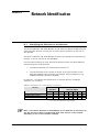
Identifying the Switchos II on the Network
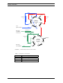
Cleanup of Proteins
C-1
C.1
C-1
Overview
Connecting Fused Silica Capillary
D-1
D.1
D.2
D.3
D.4
D-1
D-2
D-3
D-4
Overview
Fitting Assembly
Using Long PEEK Hex Style Nuts
Spare Parts Lists
I-1
INDEX
User’s Manual Switchos II
D850R3
iii
Table of Contents
[This page intentionally left blank]
iv
D850R3
User’s Manual Switchos II
Warranty
LC Packings (Netherlands) BV, warrants that the products manufactured and sold
by it to be free from defects in material and workmanship for normal use and
service from the date of delivery to original purchaser for a period of one (1) year
from the date of shipment. This limited warranty does not cover, and no
warranty is provided, for parts that by their nature are required to be replaced
periodically as a function of use of the normal operation of the system. These
items include, without limitation: HPLC columns, fuses, tubing, detector sources,
pump piston seals, injector rotors, check valves, filters, any software, etc. In
addition, damage due to corrosion, misuse, negligence, accident, alteration of the
system or repair by an unauthorized individual is not covered by the warranty. It
is understood that the performance characteristics of the instrument require that
the mobile phase be degassed with He as described in the User’s Manual.
This warranty covers products sold under the LC Products trademark. If a
different warranty than the above is indicated in the sales literature, the warranty
indicated in the sales literature will prevail. If the system includes equipment
supplied by LC Packings but manufactured by a third party, LC Packings makes
no warranty of any kind, express or implied, including, without limitation, any
warranty of merchantability or fitness for a particular purpose. LC Packings will
make available to you, to the extent permitted, the warranties of the
manufacturer of the relevant equipment following your timely written request.
If any product covered by this warranty becomes defective during the warranty
period, it will be repaired or replaced by LC Packings at no charge to the
customer (the repair/replace decision is solely at the option of LC Packings). All
warranty requests must be received by LC Packings during the warranty period.
LC Packings will pay for surface transportation to the applicable LC Packings
Office (North America – Sunnyvale CA, Europe and Asia - Amsterdam, the
Netherlands), if the instrument proves defective within thirty (30) days from the
date of shipment (this does not include air freight, drayage, labor, crating
charges, customs clearance charges, etc.). The user should carefully follow the
directions indicated on the Return Goods Instruction Sheet in the User’s Manual.
After thirty days, all transportation costs will be at the expense of the customer.
Software Warranty
If, at any time during the period ending ninety (90) days after delivery of any
product to you, you report and document any error in any software provided
with such product and developed by LC Packings or any failure of any such
software substantially to conform to LC Packings software description that limits
or prevents use of the software by you, we will use reasonable efforts to correct
any such error or failure, will replace such software or will terminate your license
to use the software and refund the price of the related product. In connection
with any such termination and refund, you will return the related product to LC
Packings upon request.
The warranty will apply only to those portions of the software that were
developed by LC Packings and that incorporated all program corrections and
modifications, if any, delivered to you. It will not apply to any error or failure due
to machine error or to the misuse by or negligence of any person or entity other
than LC Packings or to any software, which is modified by any person, or entity
other than LC Packings.
User’s Manual Switchos II
D850R3
v
Warranty
Liability
Under no circumstances shall LC Packings be liable for damage to persons or
property. This warranty is the only warranty given by LC Packings with respect
to products and software provided with the products and is given in lieu of all
other warranties, express or implied, including, without limitation, any warranty
of merchantability or fitness for a particular purpose.
Your exclusive remedies and LC Packings’s sole liability for any non-conformity
or defect in the products and such software will be those expressed herein.
Under no circumstances will LC Packings’s liability arising from the performance
or failure to perform of any product or software, in contract, in tort (including
negligence), or otherwise, exceed the purchase price of the product and
software. In no event will LC Packings be liable, in contract, in tort (including
negligence), or otherwise for special, incidental, consequential or analogous
damages, including, without limitation, damages resulting from loss of use, loss
of profits, loss of business or loss of goodwill, even if LC Packings has been
advised of the possibility of such damages.
This warranty comprises the entire warranty between LC Packings and the
customer. It overrides any warranty related language that may appear in the
customer purchase order or other documentation provided by the customer.
This warranty shall be governed by, and construed and enforced in accordance
with, the laws of the Netherlands. It is non-transferable and shall run to the
benefit of the original purchaser only. Any change, alteration or amendment to
this warranty is not valid unless it has been approved in writing by an officer of
LC Packings.
North America
LC Packings / Dionex
vi
500 Mercury Drive
Sunnyvale, CA 94088-3603
USA
Europe and Asia
LC Packings (Netherlands) BV
A Dionex Company
Abberdaan 114
1046 AA Amsterdam
The Netherlands
Technical Call Center
USA/CA: (800) 346-6390
Phone: + 31 20 683 9768
Fax:
+ 31 20 685 3452
D850R3
User’s Manual Switchos II
Instructions for Returning Instruments
Before you return any item for repair, please contact the nearest LC Packings
office or its local distributor for instructions and obtain a return authorization
number and the ‘Health and Safety Form’ (if applicable).
Pack the equipment carefully, preferably in its original shipping container and
ship it to the LC Packings Service Department, using the appropriate address.
North America
LC Packings / Dionex
500 Mercury Drive
Sunnyvale, CA 94088-3603
USA
Europe and Asia
LC Packings (Netherlands) BV
A Dionex Company
Abberdaan 114
1046 AA Amsterdam
The Netherlands
Technical Call Center
USA/CA: (800) 346-6390
Phone: + 31 20 683 9768
Fax:
+ 31 20 685 3452
IMPORTANT:
1) Make certain that the return authorization number together with the HEALTH
AND SAFETY form (if applicable) is attached outside of the package so that
we can properly track and account for your system.
2) Please include the following
a) Company letterhead with the following information.
1.
Your Name
2.
Complete Mailing Address
3.
Telephone Number, fax number and e-mail address
4.
Return Material Authorization (RMA) Number
5.
A detailed description of the problem.
6.
The name of the LC Packings personnel to whom you have
spoken to regarding the problem
7.
Return Shipping Information (if appropriate)
b) Relevant chromatograms
c) A purchase order (if the system is not in warranty)
Note: The completed and signed HEALTH AND SAFETY form must be returned
to LC Packings service department (fax or mail) prior to the return of any
component, or attached outside the shipping package. In addition, the provided
RMA number must be clearly marked on the outside of the shipping package.
Failure to complete and return this form will result in the package returned
without the parts being inspected or credit issued.
User’s Manual Switchos II
D850R3
vii
Instructions for Returning Instruments
[This page intentionally left blank]
viii
D850R3
User’s Manual Switchos II
Warnings
The Danger sign, Warning sign and the Caution sign shown below are included in
various locations in this manual. These signs provide the following information:
DANGER
Danger: The information in a danger statement relates to a procedure, practice
condition or action that if not done correctly or adhered to could lead to personal
injury or loss of life.
WARNING
Warning: The information in a warning statement relates to a procedure, practice
condition or action that if not done correctly or adhered to could lead to severe
injury and/or damage or destruction to parts or all of the equipment.
CAUTION
Caution: The information in a caution statement relates to a condition that could
lead to damage to equipment and/or lead to invalid analytical results.
Note: The information in a note statement relates to important information that
should be read and understood before continuing.
Safety Precautions
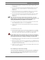
Note: The following precautions should be followed to minimize the possibility of
personal injury and/or damage to property.
Note: Make certain that you are familiar with the contents of this manual before
working on the system.
1) The system should be installed in a well-ventilated laboratory. If the mobile
phase includes volatile or flammable solvents, make certain that they are not
allowed to enter the workspace.
2) If the mobile phase includes volatile or flammable solvents, avoid open
flames and sparks.
3) If a leak occurs, turn off power to the instrument and remedy the situation
immediately.
4) All components of the system should be plugged into a common power line
that is directly connected to a true ground.
5) When the panels are removed, dangerous electrical connections will be
exposed. Disconnect the instrument from all power sources before removing
the panels.
6) Always replace blown fuses with fuses of the same size and rating indicated
on the fuse holder and panel. Refer to Section 6.3.6 of this manual for more
information on Fuses.
User’s Manual Switchos II
D850R3
ix
Warnings and Safety Precautions
7) Repair or replace faulty power cords and all communication cables.
8) Many organic solvents and buffers are toxic. Make certain that you know the
toxicological properties of all mobile phases that you are using.
9) The toxicological properties of many samples may not be well known. If you
have any doubt about a sample, treat it as if it contained a potentially
harmful substance.
10) Wear protective eye goggles when handling mobile phases or operating the
instrument. An eye wash facility and a sink should be close to the unit. If any
mobile phase splash on the eyes or skin, wash the affected area and seek
medical attention.
11) Dispose of all waste mobile phase in an environmentally safe manner that is
consistent with all local regulations. Do not allow flammable and/or toxic
solvents to accumulate. Follow a regulated, approved waste disposal
program. Never dispose flammable and/or toxic solvents through the
municipal sewage system
12) PEEK tubing is used in a variety of locations. While this polymer has superb
chemical resistance to most organic solvents, it tends to swell when it is
contact with CHCl3, DMSO and THF. In addition, it is attacked by
concentrated acids such as Sulfuric Acid and Nitric Acid (swelling or attack
by acid is not a problem with short flushing procedures).
Do not use PEEK tubing that is stressed, bent or has a kink.
13) Wear protective eye goggles when handling fused silica tubing (i.e.
installation, cutting etc.)
14) If a buffer is used as a part of the mobile phase, flush the system with
several volumes of a methanol/water (50/50) before it is shut down. This will
prevent salt buildup inside the unit.
15) Do not use the instrument in ways other than those indicated in the
instructions given in this manual.
x
D850R3
User’s Manual Switchos II
DECLARATION OF CONFORMITY
We
LC Packings Nederland BV
A Dionex Company
Abberdaan 114
1046 AA Amsterdam
The Netherlands
declare that our product
Switchos™ II Advanced Microcolumn Switching Unit
is in confirmation with the following documents:
# EEC directives 89/392, incl. 91/368 and 93/44 (machine safety) and EEC
directives 73/23 and 93/68 (low voltage safety), applied with the following
standard:
EN61010-1
Safety requirements for laboratory equipment
(Class I, Installation cat. II, Pollution degree II)
WARNING
LC Packings will not accept any liability for damages direct or indirect
caused by connecting this instrument to devices which do not meet relevant
safety standards.
# EEC directives 89/336 and 92/31 (EMC requirements), applied with the following
standards:
EN 50081-1
Generic emission standard
EN 50082-1
Generic immunity standard
EN 61000-3-2 Harmonic current emissions
Use shielded cables and connectors for all remote connections.
Amsterdam, January 11, 2001
Robert van Ling, QA manager
D934R1
User’s Manual Switchos II
D850R3
xi
CE Declaration
[This page intentionally left blank]
xii
D850R3
User’s Manual Switchos II
CHAPTER 1
Introduction
1.1 Features of the Switchos™ II Advanced Microcolumn
Switching Unit
The Switchos™ II Advanced Microcolumn Switching Unit is an advanced
switching system for use with micro-HPLC systems. The system incorporates the
following features:
• Two Valco 10-port low-dispersion switching valves which allow for the
connection of capillary, micro and nano HPLC columns without any dead
volume.
• A high precision loading pump, fully controllable by the CHROMELEON®
software.
• Four channel solvent selection valve.
• Automatic control of all valves by the CHROMELEON software and manual
control via push buttons.
• Manual valve switching is possible at any time, even when a program is
running.
• LED’s which indicate the present status of the switching valves (microfluidic
pathways), the position of the solvent selection valve and the control mode.
A broad range of applications can be performed using micro-column switching
with the Switchos II including sample preconcentration, sample cleanup, multidimensional separations (2-D separations), desalting and selective extraction
Typical examples of the use of the unit (which are described in Section 2.6.4 and
Appendix C) include immuno-affinity extractions, isolation of phosphorylated
peptides from complex protein digests, automated removal of detergents,
extraction of drugs from biological fluids, high throughput analysis, etc.
Switchos II is configured with an LC Packings UltiMate™ Micropump and is
normally used with the LC Packings UltiMate Capillary HPLC System. The system
is fully compatible with other instrumentation (a minimum of three contact
closures, TTL or Open Collector terminals are required).
User’s Manual Switchos II
D850R3
1-1
Introduction
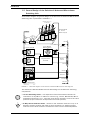
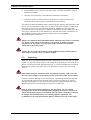
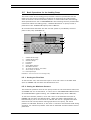
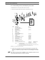
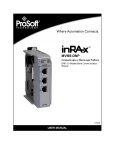
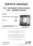
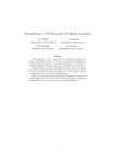
1.2 General Design of the Switchos II Advanced Microcolumn
Switching Unit
A schematic diagram of general design of the Switchos II Advanced Microcolumn
Switching Unit is presented in FIGURE 1-1.
Solvent lines A - D
to the SSV
(a)
Solvent Bottles
A - D with
Bottle Caps (a)
Front Panel
He to
Bottle Caps
He
Regulating
Valve
A
D
C
B
Solvent Tray
10-port valve A
He Inlet
4-way Solvent
Selection Valve
He Line
Check Valve
A
D
B
C
COMMUNICATION
10-port valve B
Integrated Valve
Controller
Remote
Control
INPUTS
Loading Pump
RS-232-1
Network
RS-232-2
loading flow
to application
Rear Panel
High Pressure Filter
FIGURE 1-1. Schematic Diagram of the Switchos II Advanced Microcolumn Switching Unit
The Switchos II Advanced Microcolumn Switching Unit includes the following
components:
• 10-Port Switching Valves - low dispersion valves assure dead volume free
connection of any Micro- or Nano LC column (e.g., Fusica, NanoSeries, Microand Nano-Precolumns, etc.). Two fast motor-driven actuators control the valve
positions (6 port valves are incorporated into some systems).
A
D
B
C
1-2
• 4-Way Solvent Selection Valve - allows for the automatic selection of up to 4
different solvents without the need of pump shut down or tedious purging.
One fast motor-driven actuator switches the valve into the selected position.
D850R3
User’s Manual Switchos II
Introduction
• Loading Pump - designed for the use in the LC Packings UltiMate Capillary
HPLC system, the micropump guarantees highest performance and perfect
compatibility. It is fully controllable via the CHROMELEON software.
• Solvent Bottles and He Degassing System - provides mobile phase to the
system. The Helium degassing system is provided to improve check valve
reliability and diminish baseline noise.
• Integrated Valve Controller - micro-controller based electronics controls the
valve actuators and monitors the position of the three valves (valve A, valve B,
solvent selection valve). Additionally, it reads the COMMUNICATION port and
reads out the status of the push buttons, switches and the remote control
input connector.
• High Pressure Filter - serves to remove particulate matter from the mobile
phase.
Note: For highest performance, complete automation and ease of operation, the
Switchos II Advanced Microcolumn Switching Unit should be used in combination
with the LC Packings UltiMate™ Capillary HPLC system and the FAMOS
Microautosampler. These units can be readily connected via a local area network
(Chapter 2.3) for secure communication between the various modules.
User’s Manual Switchos II
D850R3
1-3
Introduction
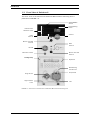
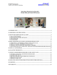
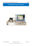
1.3
Front View of Switchos II
The front view of the Switchos II Advanced Microcolumn Switching Unit is
presented in FIGURE 1-2.
ON/STANDBY
Switch
He Regulating
Valve
LEDs Solvent
Selection Valve
Valve A
LEDs
Valve A
Button with LED
Valve A
LEDs
Valve B
Valve B
Button with LED
Valve B
Microflow Outlet
Loading Pump
Keyboard
Backflushing
Connections
Pump Head
Purge Screw
High Pressure
Filter
Inlet
FIGURE 1-2 Front View of the Switchos II Advanced Microcolumn Switching Unit
1-4
D850R3
User’s Manual Switchos II
Introduction
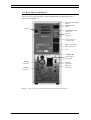
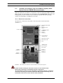
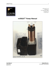
1.4 Rear View of Switchos II
The rear view of the Switchos II Advanced Microcolumn Switching Unit is
presented in FIGURE 1-3.
SOLVENT SELECTION
Button
REMOTE/LOCAL
Switch
He Inlet
COMMUNICATION
Connector
INPUTS
Connector
Power Outlet to
Loading Pump
Main Power Switch
Main Power Inlet
Fuse
Loading Pump
Power Switch
Power Inlet
EVENTS
Connector
RS-232-1
Connector
RS-232-2
Connector
REMOTE
Connector
FIGURE 1-3 Rear View of the Switchos II Advanced Microcolumn Switching Unit
User’s Manual Switchos II
D850R3
1-5
Introduction
1.5 Contents of this Manual
Note: This manual covers the standard version of the Switchos II Advanced
Microcolumn Switching Unit as well as the inert version. If you are using an inert
version, please refer to Appendix D, which includes important information about
how to connect fused silica tubing to the inert switching valves.
This manual includes the following information:
Chapter 2:
Installation and Getting Started describes how to install the
Switchos II Advanced Microcolumn Switching Unit.
Chapter 3:
The User Interface describes the system controls, explains how
the unit is used in manual mode and provides a short overview of the micropump
controls. A detailed discussion of the micropump is presented in the UltiMate
Micropump User’s Manual, which is supplied with the system.
Chapter 4:
Software Control discusses how to control the Switchos II
Advanced Microcolumn Switching Unit by the CHROMELEON software and how
to setup the software modules.
Chapter 5:
Testing the Switchos II describes a series of operations to
determine that the unit is functioning in an acceptable manner.
Chapter 6:
Maintenance and Troubleshooting describes a variety of
maintenance procedures to optimize the performance of the microcolumn
switching unit. In addition, it discusses how the operator can determine the
cause of a difficulty in the operation of the instrument and includes a list of
spare/replacement parts.
Chapter 7:
Specifications presents the specifications of the Switchos II
Advanced Microcolumn Switching Unit.
In addition, a series of appendices that provide information about the valves that
are incorporated in the unit, interfacing the unit to the local area network, and
typical applications:
Appendix A: Switching Valves describes the valves that are included in the
Switchos II Advanced Microcolumn Switching Unit. In addition, it presents
information about the disassembly and reassembly of the valve.
Appendix B:
Network Identification provides explains how the Switchos II is
identified on the system network so that it can communicate with other
components.
Appendix C: Cleanup of Proteins presents an explanation of how the
Switchos II is used for sample clean-up, protein digestion and peptide separation.
Appendix D: Connecting Fused Silica Capillary explains how to connect a
NANO column or other fused silica capillary to the inert PAEK switching valves of
the Switchos II.
1-6
D850R3
User’s Manual Switchos II
Introduction
1.6
For Additional Information
The loading pump that is incorporated in the Switchos II Advanced Microcolumn
Switching Unit is identical to the micropump supplied with the LC Packings
UltiMate™ system. If you are using the Switchos II Advanced Microcolumn
Switching Unit with the LC Packings UltiMate™ and/or CHROMELEON software,
please refer to the documentation provided with these products for supplemental
information and to the online help of CHROMELEON (F1 key).
In addition to the ‘Switchos II Advanced Microcolumn Switching Unit - User’s
Manual’ this binder contains a copy of the User’s Manual for the LC Packings
UltiMate™ Micropump. The ‘UltiMate Micropump User’s Manual’ contains a
detailed discussion about the operation and maintenance of the Micropump.
User’s Manual Switchos II
D850R3
1-7
Introduction
[This page intentionally left blank]
1-8
D850R3
User’s Manual Switchos II
Installation and Getting Started
CHAPTER 2
2.1
Installation
The instructions provided below are provided for installation of the Switchos™ II
Advanced Microcolumn Switching Unit as part of the LC Packings UltiMate™
Capillary HPLC System as well as for installation of the instrument as a standalone component in an HPLC system.
When the Switchos Advanced Microcolumn Switching Unit is used in conjunction
with the UltiMate system and the FAMOS™ Microautosampler, all instruments
are controlled by the CHROMELEON® software. The loading pump will be
included in the instrument network and the switching valves will be controlled by
a COM port of the PC.
If no additional COM port is available or if the Switchos is to be installed with
different or third-vendor software, please refer to Sections 2.4 and 2.5 for
information about how to control the switching valves by relay outputs. (e.g. the
Event outputs of the Switchos loading pump or the Auxiliaries of the FAMOS
Microautosampler, if present).
Once you have set up the Switchos, refer to Section 2.7 for information about
routine operation of the system.
Please refer to the user’s manuals of the UltiMate system and the FAMOS
Microautosampler and the online help of CHROMELEON for additional
information.
2.1.1 Location of Switchos in the Laboratory
The Switchos Advanced Microcolumn Switching Unit should be installed in a
facility with the following environmental conditions:
•
The temperature range should be maintained between 10 and 40oC. The
system should be installed in an area in which the temperature is fairly
constant (do not place the system near a window, an air conditioning duct or
a heating duct). The humidity should be maintained between 20 and 80 %
relative humidity.
User’s Manual Switchos
D850R3
2-1
Installation and Getting Started
•
If flammable or toxic solvents are to be used, a suitable ventilation system
should be provided.
•
The use of open flames in the laboratory should be prohibited.
•
Corrosive vapors or dust should not be present as these materials can
adversely affect the long-term performance of the system.
The Switchos Advanced Microcolumn Switching Unit requires approximately 190
mm (7.5”) of linear bench space. The lab bench should be capable of supporting
the entire system (for the LC Packings UltiMate, FAMOS and Switchos we
recommend that the lab bench be capable of supporting at least 100kg (225 lb.).
The power consumption of the Switchos is 100 VA (the power consumption of
the UltiMate Capillary HPLC System is 250 VA and of the FAMOS
Microautosampler is 250 VA).
DANGER
Danger: The Switchos Advanced Microcolumn Switching Unit must be connected
to a power source that is connected to a true ground. In addition, all other
components of the system (e.g. the HPLC pump, the detector) should be
connected to the same ground.
CAUTION
Caution: Do not install the Switchos Advanced Microcolumn Switching Unit in
areas subject to shock, dust, or in direct sunlight.
2.2
Unpacking
When the Switchos Advanced Microcolumn Switching Unit is received, carefully
unpack the unit and verify receipt of all components according to the packing list
(some components include sub-packing lists). It is recommended that all packing
materials be saved in the event that it is necessary to return any item to the
factory.
CAUTION
Note: When lifting the instrument from the shipping container, make sure that
the unit is kept upright. Lift the unit by placing your hands under the instrument.
If there is external damage to the shipping box, the damage should be reported
to the shipping agent and LC Packings upon receipt of the goods. If internal
damage is observed or if any items are missing, this should be reported to the
shipping agent and to LC Packings as soon as it is observed.
CAUTION
2-2
Note: If there is any apparent damage to the instrument, the user should
investigate the nature of the damage before plugging the unit into the mains to
ensure that powering up of the instrument will not create a hazardous condition
or damage internal components. If the damage appears significant, call
LC Packings or its local representative before connecting the unit to the mains.
D850R3
User’s Manual Switchos
Installation and Getting Started
2.3
Installing the Switchos with the UltiMate Capillary HPLC
System and the FAMOS Microautosampler
When the Switchos is used as a component in the LC Packings UltiMate Capillary
HPLC system, all instruments are controlled by the CHROMELEON software. The
loading pump will be included in the instrument network and the switching
valves are controlled by a COM port of the PC.
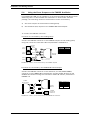
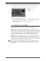
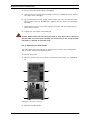
2.3.1 Electrical Connections
All electrical connections are made on the rear panel of the instrument
(FIGURE 2-1).
SOLVENT SELECTION
Button
REMOTE/LOCAL
Switch
He Inlet
COMMUNICATION
Connector
INPUTS
Connector
Power Outlet to
Loading Pump
Main Power Switch
Main Power Inlet
Fuse
Loading Pump
Power Switch
Power Inlet
EVENTS
Connector
RS-232-1
Connector
RS-232-2
Connector
REMOTE
Connector
FIGURE 2-1 Rear Panel of the Switchos Advanced Microcolumn Switching Unit
CAUTION
Caution: Avoid touching the electrical contacts on the terminal strips.
Electrostatic discharges could damage internal components.
The manufacturer will not accept any liability for damages directly or indirectly
caused by connecting the Switchos Advanced Microcolumn Switching Unit to
instruments which do not meet relevant safety standards.
User’s Manual Switchos
D850R3
2-3
Installation and Getting Started
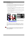
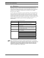
2.3.2 RS-232 Connectors
The two RS-232 serial interfaces enable digital data transfer between the loading
pump, the UltiMate Micropump, the UltiMate UV Detector (if present) and the
PC. These devices communicate with each other to form an integrated network.
To set up the RS-232 network connections:
•
Connect the RS-232 1 connector of the Switchos loading pump, the RS-232
2 connector of the UltiMate UV Detector and the COM port of the PC using
the Y-cable (item a, FIGURE 2-2).
•
Connect the RS-232 2 connector of the Switchos loading pump and the RS232 1 connector of the UltiMate Micropump using the Serial Communication
Cable (item b, FIGURE 2-2).
•
Connect the RS-232 2 connector of the Micropump and the RS-232 1
connector of the UV Detector with the same type of cable.
UltiMate
Item
Switchos II
P/N
Cable
9 pin
female
a
9 pin
female
160069
9 pin
male
b
b
160070
9 pin
male
1:1
9 pin
female
c
160071
9 pin
female
Null-Modem
9 pin
female
c
b
a
PC COM port X (SW II Valve Control)
PC COM port Y (Solvent Organizer)
PC COM port Z (ULT/SWII Network)
c
FIGURE 2-2 Setting up the RS-232 Network Connections
If your configuration does not include an UltiMate UV Detector, connect the
y-cable to the RS-232 1 connector of the UltiMate Micropump, the RS-232 2
connector of the Switchos loading pump and the COM port of the PC. Use a
Serial Communication Cable to connect the other RS-232 connectors of both
pumps.
CAUTION
2-4
Caution: The RS-232 sockets are to be used only with LC Packings software
products (e.g. CHROMELEON) or third vendor software that support the LC
Packings UltiMate System.
D850R3
User’s Manual Switchos
Installation and Getting Started
2.3.3 COMMUNICATION Connector
Connect the COMMUNICATION port to a free COM port on the computer using
the Solvent Organizer Com cable (item c, FIGURE 2-2).
2.3.4 INPUTS Connector
CHROMELEON controls the valve positions via the COMMUNICATION port
(Section 2.3.3). Refer to Sections 2.4 and 2.5 if the valves need to be controlled
by digital input signals (e.g. the instrument is to be installed in conjunction with a
software package which does not support the serial communication).
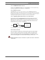
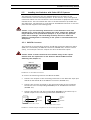
2.3.5 Triggering a Mass Spectrometer (or an Other Device)
If you want to provide a mass spectrometer (or other external device) with a
trigger signal from the CHROMELEON software at some event (e.g. on the
beginning of the gradient program), connect the appropriate input of the mass
spectrometer (or other device) to the EVENT 8 output (relay contact) of the
UltiMate Micropump as shown in FIGURE 2-3.
UltiMate
Micropump
EVENT 8
(Relay)
Mass Spectrometer
or
other device
{
FIGURE 2-3 Cable to trigger the MS (or another Device) by EVENT 8
2.3.6 Power Connector
Since the Switchos is fitted with a universal power supply for input voltages
from 90 to 260 V, manual setting of the supply voltage is not required. The
power cord should be inserted in the socket directly below the Main Power
switch on the right side of the rear panel (FIGURE 2-1). In addition, the loading
pump should be plugged into the socket above the Main Power switch.
DANGER
Danger: The Switchos must be connected to a power source that is connected to
a true ground.
User’s Manual Switchos
D850R3
2-5
Installation and Getting Started
2.4
Using the Event Outputs or the FAMOS Auxiliaries
If no additional COM port is available or if the Switchos Advanced Microcolumn
Switching Unit is to be installed with a different or third vendor software
package, the switching valves on the Switchos can be controlled by:
a)
the event outputs of the Switchos Loading Pump.
b)
the Auxiliaries (P5) outputs of the FAMOS Microautosampler.
To connect the INPUTS connector:
a) Valves are controlled by the Loading Pump
Connect the INPUTS connector to the EVENTS outputs of the loading pump
using the connection cable P/N 160172 presented in FIGURE 2-4.
EVENT3
GROUND
Switchos
Events
Micropump Switchos II
EVENT3
Valve A
EVENT6
Valve B
EVENT7
SSV
EVENT8
Trigger
EVENT6
GROUND
{
{
Switchos
INPUTS
EVENT7
EVENT8
to MS or another device
FIGURE 2-4 Cable to control Switchos by the UltiMate System
b) Valves are controlled by the FAMOS Microautosampler
Connect the INPUTS connector of the Switchos, the P5 (AUXILIARIES)
connector of the FAMOS Microautosampler and the START IN input of the
UltiMate UV Detector using the connection cable P/N 160171 presented in
FIGURE 2-5.
FAMOS
(P5 Auxiliaries)
Switchos
(INPUTS)
FAMOS
AUX1
AUX2
AUX3
AUX4
Switchos II
Valve A
Valve B
SSV
START IN
UltiMate
UV Detector
(START IN)
FIGURE 2-5 Cable to control Switchos by the FAMOS P5 Connector
2-6
D850R3
User’s Manual Switchos
Installation and Getting Started
2.5
Installing the Switchos with Other HPLC Systems
The electrical connections that are required depend on the nature of the
instrumentation and the desired application. In this section, we provide general
information about how the instrument can be interfaced to equipment from other
manufacturers. The user should also refer to the documentation provided with
this equipment. The Switchos is controlled via the INPUTS connector on the rear
panel and the keypad of the loading pump.
CAUTION
Caution: If you are interfacing the Switchos to instrumentation from other
manufacturers, ensure that input voltages and output voltages are within the
ranges indicated in the specifications (Chapter 7). If you have any questions,
please call LC Packings. The LC Packings warranty will not be valid if the
Switchos is damaged due to interfacing of the system to instrumentation from
third parties.
2.5.1 INPUTS Connector
The positions of the switching valves A and B and the Solvent Selection Valve
(SSV) are controlled by the INPUTS connector (FIGURE 2-6). Contact closure
(relay), TTL and open collector outputs can drive the Switchos inputs.
CAUTION
Caution: Check to make certain that the maximum ratings of the outputs
matches with the requirements of the Switchos Advanced Microcolumn
Switching Unit (Chapter 7).
PIN #
1
2
4
5
7
8
INPUTS
8
15
1
9
SIGNAL
VALVE A
GROUND
VALVE B
GROUND
SSV
GROUND
FIGURE 2-6 Pin-Out INPUTS Connector
To control the switching valves A and B and the SSV:
•
Connect two outputs of the controlling instrument to the Switchos input pins
VALVE A and VALVE B of the INPUTS connector (FIGURE 2-7).
•
Connect the common terminals or the ground terminals of the controlling
instrument to the corresponding GROUND pins of the INPUTS connector
(FIGURE 2-7).
•
Connect the SSV pin and the corresponding GROUND in the same way to
another output of the controlling instrument (FIGURE 2-7).
Controlling
Instrument
Relay
VALVE A
VALVE B
SSV
Controlling
Instrument
GROUND
GROUND
A) Contact Closure (Relay) Output
VALVE A
VALVE B
SSV
B) TTL / Open Collector Output
FIGURE 2-7 Different Output Configurations of the Controlling Instrument
User’s Manual Switchos
D850R3
2-7
Installation and Getting Started
VALVE A(B) - these two pins control the two switching valves. An open contact
closure or an inactive TTL (or open collector) output will drive the corresponding
valve into position “1-2”, while an active input will drive the corresponding valve
into position “10-1”. The current positions are indicated by the LEDs on the front
panel (FIGURE 1-2).
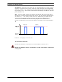
SSV – this pin is used to select the position of the SSV. An active input signal
shorter than 1.5 seconds will switch the valve to the next solvent channel (from
A to B, B to C, … and finally from D back to A). Additionally, the SSV can be
reset to solvent channel A by applying an active signal for longer than
1.5 seconds. FIGURE 2-8 shows the timing diagram. The selected solvent
channel is indicated by one of the four LEDs on the upper front panel (FIGURE 12).
Reset to
Channel A
Step to next
Channel
active
inactive
t1
t1 +1 s
t2
t2 +2 s
t2 +3 s
T
FIGURE 2-8 Timing Diagram of the SSV Input
2.5.2 Power Connector
Connect the Switchos to the power line as described in Section 2.3.6.
DANGER
2-8
Danger: The Switchos must be connected to a power source that is connected to
a true ground.
D850R3
User’s Manual Switchos
Installation and Getting Started
2.6
Fluidic Connections - Switchos to the HPLC System
2.6.1 Preliminary Operations
To connect the Switchos Advanced Microcolumn Switching Unit to an HPLC
system and to prepare the instrument for operation:
•
Place the Switchos Advanced Microcolumn Switching Unit in its operating
location, preferably on the left side of the HPLC system. Make sure the
ventilation holes are not obstructed. Allow the instrument to acclimatize for 1
hour.
•
Connect the Helium line (Section 2.6.2).
•
Power-up the system. The display of the loading pump and the various LED’s
will indicate that the self-test and initialization have been executed. A
detailed discussion about the control and the various display messages of the
loading pump is presented in the ‘UltiMate Micropump User’s Manual’.
•
Sparge the mobile phase and flush the solvent lines (Section 2.6.3).
•
Prepare the fluidics connection according to your needs. A typical example is
shown in Section 2.6.4 (additional examples are presented in Appendix C).
CAUTION
Caution: Do not use a stainless steel nut and/or ferrule with the inert (PAEK)
injection/switching valves. The use of stainless steel nuts or ferrules may
damage the valve. Use only the supplied fittings (PEEK) and follow the
instructions below. If you are using an inert version, please refer to Appendix D,
for important information about how to connect fused silica tubing to the inert
switching valves.
CAUTION
Caution: Use the fittings supplied with the instrument (Valco) or equivalent
fittings to ensure that the dead volume of the system is minimized. Use of
Rheodyne fittings should be avoided. Rheodyne fittings are designed differently;
they will lead to unswept volume and possible system damage.
2.6.2 He Connection
Connect the Helium line (1/4 “ O.D.) that is supplied to the Helium inlet on the
rear panel of the Switchos (FIGURE 2-1). To connect the Helium line of the
Switchos to the Helium line of the UltiMate Capillary HPLC System, use the Tpiece (P/N 161470) that is supplied with the Switchos instrument. The Helium
pressure should be set to approximately 1 bar.
CAUTION
Caution: Do not operate the He lines at a higher pressure than 4 bar (60 psi).
Close the He-shut off valves when the system is in idle state or not used.
User’s Manual Switchos
D850R3
2-9
Installation and Getting Started
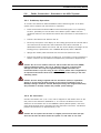
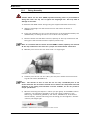
2.6.3 Sparging the Mobile Phase and Flushing the Solvent Lines
Although the Switchos loading pump is controlled via the CHROMELEON
software, initial system preparation is done with the pump on an off-line basis
(i.e. the pump is operated locally).
To prepare the system for a separation:
a) Power up the Switchos and make certain that power is provided to the
pump.
b) Check that the pump head backflushing system is operating. A solution of
isopropanol/water (1:1) is commonly used but other solvents can be used (if
any of the buffer components are not soluble in this mixture, reduce the
fraction of propanol). If desired you can reduce evaporation of the
backflushing solution by connecting the two backflush ports. A 5 mL syringe
is provided to backflush the head and fill the reservoir.
Note: The pump head of the pump should be backflushed with propanol/water
(1:1). If crystalline materials are deposited in the pump head, irreversible damage
to seals and or the piston may result; this will dramatically shorten the life of
these components.
c) Inspect all fittings. If there is a salt deposit by a joint, it is probable that a
leak has occurred and the fitting should be cleaned and tightened. When you
tighten a fitting, do not overtighten. Check that the solvent filters are clean,
if not they are not clean, they should replaced.
d) Fill the solvent reservoirs with the mobile phases to be used for the
application.
CAUTION
Caution: Only use the shielded solvent reservoirs supplied with the Switchos.
CAUTION
Caution: Do not operate the He lines a higher pressure than 4 bar (60 PSI).
Close the He-shut off valves when the system is in idle state or not used.
Note: All four solvent bottles must be filled and purged (even if the application
requires less than four mobile phases) to assure proper function of the system.
Fill solvent bottles that will not be used with methanol/water (1/1).
Note: The solvents must be degassed via the He degassing technique described
below. If other techniques are used (e.g. vacuum degassing) the performance of
the system will be seriously degraded and the performance specifications will not
be obtained.
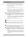
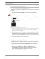
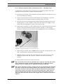
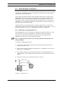
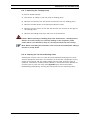
e) Open the He Shut-off valves by rotating the knob so that the line on the
valve is vertical (FIGURE 2-9) and open the He Regulating Valve for maximum
sparging (FIGURE 2-10A). Allow sparging to continue for approximately 10
minutes at a rapid rate, then lower the He flow rate to maintenance mode
(FIGURE 2-10B).
2-10
D850R3
User’s Manual Switchos
Installation and Getting Started
Vent
He Shut-Off
Valve
FIGURE 2-9 He Shut-Off Valve
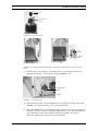
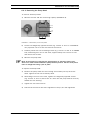
He
Outlet
Solvent
Inlet
(A)
(B)
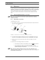
FIGURE 2-10 (A) Rapid Sparging (B) Sparging – Maintenance Mode (Shield removed to provide
clarity)
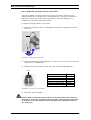
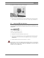
f)
Connect the 5 mL syringe to the purge outlet on the purge valve on the
loading pump using 1/16” ID silicon tubing (FIGURE 2-11).
Purge Valve
Knob
Outlet
FIGURE 2-11 The Purge Valve
g) Open the purge valve on the loading pump by turning the purge valve knob
(FIGURE 2-11) approximately 1 turn counterclockwise.
h) Press the PURGE key on the loading pump, set the flow rate of the to 0.0 mL
and select solvent channel A using the SSV button on the rear side (Section
3.3). Withdraw solvent from bottle A using the syringe until no air is
observed. Repeat this process for all four channels.
User’s Manual Switchos
D850R3
2-11
Installation and Getting Started
i)
Set the purge flow to 0.5 mL/min. Allow the system to purge for at least 3
min. After line A has been purged, repeat the process for all other lines.
j)
Close the purge valve on the loading pump by turning the purge valve knob
clockwise.
k) Close the He shut-off valve(s) on top of the solvent bottles that will not be
used (the white line should be horizontal).
l)
Place the loading pump under computer control and deliver mobile phase
through the entire HPLC system at the flow rate and from the solvent
reservoir that are used for the initial conditions for the analysis that you
intend to perform. As the system is delivering mobile phase, check for leaks,
monitor the baseline and check that the pressure is similar to what was
observed when the system was last used.
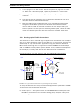
2.6.4 Setting-up the Fluidic Connections
The Switchos is used in a broad range of applications and the user can configure
the unit to meet the specific needs of the laboratory. In this section we show the
fluidic setup of a pre-concentration application using the Switchos Advanced
Microcolumn Switching Unit in conjunction with the FAMOS Microautosampler
and the UltiMate Capillary HPLC System (FIGURE 2-12). Additional examples are
presented in Appendix C. While these examples may not meet the specific needs
of the analyst, it is likely that they can be used with minor modification.
Pre-Concentration using the Switchos and the FAMOS Microautosampler
Analytical microcolumn
FAMOS
port 6
Micro flow
to UltiMate
Switchos
Waste
Valve A
2
3
Trap column
FAMOS
port 1
4
5
1
10
Valve A
presented
in position
1-2
6
9
8
7
Micro flow
from UltiMate
Waste
FIGURE 2-12 Typical Pre-Concentration Setup (Loading the Trap Column)
To setup the Switchos for the pre-concentration application presented in FIGURE
2-12, connect the instruments as follows:
a) Connect port 1 of the injection valve of the FAMOS Microautosampler to the
Nano/Micro flow outlet of the Switchos loading pump using the 130 µm I.D.
PEEK tubing provided with the instrument:
2-12
D850R3
User’s Manual Switchos
Installation and Getting Started
Dimension
50 cm x 130 µm I.D.
100 cm x 130 µm I.D.
Standard Version
P/N 160180
P/N 160181
Inert Version
P/N 160180
P/N 160181
b) Connect port 6 of the injection valve of the FAMOS Microautosampler to the
port 1 of valve A of the Switchos II as described in item a).
c) Connect the outlet flow of the UltiMate System (e.g. on the left side panel or
from the upper T-Piece of the flow splitter) to port 4 of valve A of the
Switchos. Use the appropriate tubing for your application.
Application (I.D.)
Capillary LC (50 µm)
Nano LC (20 µm)
Standard Version
P/N 161479
P/N 160178
Inert Version
P/N 161261 (1)
P/N 161259 (1)
(1) use PEEK fingertight fittings only
d) Connect port 3 of valve A of the Switchos to the UltiMate column bulkhead or
directly to the micro column located in the UltiMate column compartment. Use
the appropriate tubing for your application.
Application (I.D.)
Capillary LC (50 µm)
Nano LC (20 µm)
Standard Version
P/N 161480
P/N 160179
Inert Version
P/N 161262 (1)
P/N 161260 (1)
(1) use PEEK fingertight fittings only
e) Connect ports 6 and 10 of valve A of Switchos to waste (e.g. using 200 500 µm I.D. PTFE tubing).
f) Connect the trap column between ports 2 and 5 of valve A of the Switchos II,
using the appropriate tubing supplied with the trap column.
A typically loading solvent is 100% water with 0.05% TFA. Fill solvent bottle A
with this solvent. Fill bottle B with either the same solvent or a mixture of
methanol/water (1:1), bottles C and D may be left empty).
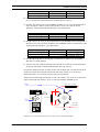
After pre-concentrating the sample on the trap column, the valve A of Switchos
will be switched into position 10-1 to elute the sample (FIGURE 2-13).
Analytical microcolumn
FAMOS
port 6
Micro flow
to UltiMate
Switchos
Waste
Valve A
2
3
Trap column
FAMOS
port 1
4
5
1
10
Valve A
presented
in position
10-1
6
9
8
7
Micro flow
from UltiMate
Waste
FIGURE 2-13 Eluting Sample adsorbed on the Trap Column (in Backflush Mode)
User’s Manual Switchos
D850R3
2-13
Installation and Getting Started
2.7
Routine Operation of the System
2.7.1 Sample and Mobile Phase Considerations
The Switchos Advanced Microcolumn Switching Unit is used in an HPLC system
and the “standard” operating precautions for HPLC should be employed:
CAUTION
2-14
•
Ensure that samples and mobile phases do not contain particulate matter. All
samples and mobile phases should be filtered through a 0.22 µm membrane
filter. If organic solvents are used, make sure that extractable materials are
not present in the filter.
•
The sample should be soluble in the mobile phase. If a gradient is used, make
certain that the sample is soluble in the mobile phase at all mobile phase
compositions to be used in the separation.
•
After you have finished using the system, flush it with a water/methanol or
water/acetonitrile mobile phase before shutting it down.
•
Solvent should be degassed by sparging with Helium.
•
Make certain that the sample and the buffer are soluble in all compositions of
the mobile phase that will be used in the separation. This test should be run
in a beaker or test tube so that particulate matter does not enter the system.
If any cloudiness is observed in the test, the gradient should be adjusted and
repeated.
Caution: It is strongly recommend that only bottled HPLC water and solvent be
used. If water from water purification systems is used, polymeric contamination
may seriously damage the column and the flow cell. This is especially true if
sample pre-concentration or 2D separations are performed. This polymeric
contamination may also seriously damage the flow cell (e.g. coating of the
capillary walls).
D850R3
User’s Manual Switchos
The User Interface
CHAPTER 3
3.1
Overview
This chapter describes the general mode of operation of the Switchos™
Advanced Microcolumn Switching Unit. It includes the following information:
•
Powering Up the Switchos (Section 3.2)
•
A description of the controls on the front and rear panel (Section 3.3)
•
LOCAL vs. REMOTE Control (Section 3.4)
•
Basic Operations for the Loading Pump (Section 3.5)
User’s Manual Switchos
D850R3
3-1
The User Interface
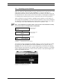
3.2
Powering up the Switchos
When the Switchos Advanced Microcolumn Switching Unit is powered up via the
main power switch on the rear panel (FIGURE 2-1), it will go through an
initialization/self-test protocol. During this period, all LEDs on the front panel will
be illuminated for a short period of time and a number of messages are displayed
on loading pump indicating that various components are functioning properly.
After completion of this procedure, the Main Screen appears on the display of
the loading pump (FIGURE 3-1) and the Solvent Selection Valve will be switched
to channel A. The LEDs indicating the current status of the Switchos (e.g. LED 12 in the upper front panel indicates that valve A is in position ‘1-2’).
Note: The initialization procedure takes a few seconds. The instrument is ready
to use when LED A of the SSV LEDs is illuminated.
Kernel Screen with
version number
Kernel
V x.xx
Firmware Screen with
version number
UltiMate
V x.xx
OFF
Main Screen
0.500 000
25 25 25 25
FIGURE 3-1. Loading Pump Start-Up Screens
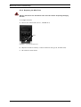
The system can be switched into standby mode (e.g. when not used over night)
by pressing the ON/STANDBY push button (FIGURE 3-2) for greater than 2
seconds. This turns off the power to the loading pump, illuminates the Standby
LED and places the Switchos into standby mode. When the system is in standby
mode, pressing the button for a short time will power on the system again (and
switch the Standby LED off).
ON/Standby Push
Button with LED
FIGURE 3-2 The ON/Standby Switch
3-2
D850R3
User’s Manual Switchos
The User Interface
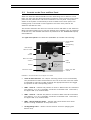
3.3
Controls on the Front and Rear Panel
When the Switchos Advanced Microcolumn Switching Unit is used on a local
basis, the user sets the desired operating conditions via the controls on the front
panel and the push button and switch located on the rear panel. The present
status of the system is indicated by a series of LEDs on the front panel. The
loading pump is controlled via the keypad on the lower front panel of the
Switchos (see Section 3.5).
This section describes the use of the various controls and LEDs on the Switchos.
Basic information about how to use the keypad of the loading pump is presented
in Section 3.5, and detailed information is presented in the ‘UltiMate Micropump
User’s Manual’.
The upper front panel of the Switchos (FIGURE 3-3) includes the following:
ON/STANDBY
Switch
He Regulating
Valve
LEDs Solvent
Selection Valve
Valve A
LEDs
Valve A
Button with LED
Valve A
LEDs
Valve B
Valve B
Button with LED
Valve B
Microflow Outlet
FIGURE 3-3 Control Elements on the Upper Front Panel
•
Valve A and B Controls– the 10-port switching valves can be controlled by
two push buttons when the Switchos is set into local mode. The local mode
is indicated by the built-in LEDs. Pressing the appropriate button will toggle
the position of the corresponding valve.
•
LEDs - Valve A – indicate the position of valve A. When Valve A is switched
into position “1-2” (e.g. the fluidic connection is between inlet 1 and inlet 2,
the upper LED (1-2) is illuminated).
•
LEDs - Valve B – indicate the position of valve B. When valve B is switched
into position “1-2” (e.g. the fluidic connection is between inlet 1 and inlet 2,
the upper LED (1-2) is illuminated).
•
LEDs - Solvent Selection Valve – indicate the solvent bottle from which
solvent is being withdrawn at the present time.
•
He Regulating Valve – used to control the flow of He for sparging (see
Section 2.5).
User’s Manual Switchos
D850R3
3-3
The User Interface
The upper rear panel of the Switchos (FIGURE 3-4) includes the following:
SOLVENT SELECTION
Button
REMOTE/LOCAL
Switch
FIGURE 3-4 Control Elements on the Upper Rear Panel
•
SSV (Solvent Selection Valves) Button – pressing the button will step to the
next solvent channel, from A to B, B to C, … and finally from D back to A.
•
LOCAL/REMOTE Switch – used to select the control mode.
3.4
LOCAL Mode vs. Remote MODE
The control mode of the Switchos Advanced Microcolumn Switching Unit can be
set via the REMOTE/LOCAL switch on the rear panel (FIGURE 3-4):
LOCAL mode - when the REMOTE/LOCAL switch is set to LOCAL mode (the
switch is set to the upper or lower position), the unit can be controlled on a local
basis by the push buttons and switches on front and rear panel. Any change that
is made will override the present condition (regardless of whether it was set via
Local or Remote Control). When the unit is in LOCAL mode, the INPUTS
connector is disabled and the built-in LEDs in the push buttons are illuminated.
REMOTE mode - when the REMOTE/LOCAL switch is set to REMOTE mode (the
switch is in the middle position) the instrument is controlled by an external
device. In this mode, the INPUTS connector is enabled and the built-in LEDs and
the push buttons are deactivated The switching valves A and B will be positioned
according to the current signals of the INPUTS connector.
Note: If the instrument is in REMOTE control mode and the INPUTS connector
on the rear panel is not connected, switching valves A and B are “locked” in
position ‘1-2’.
3-4
D850R3
User’s Manual Switchos
The User Interface
3.5
Basic Operations for the Loading Pump
The main screen of the loading pump includes a series of parameters that are
used to set the principal operating conditions for delivering the mobile phase,
such as the flow rate and maximum pressure. In automated mode (networking)
these parameters are set via CHROMELEON. The following sections provide basic
information about the loading pump, a detailed discussion on pump control is
presented in the ‘UltiMate Micropump User’s Manual’.
All communication between the user and the system is provided by the front
panel of the pump (FIGURE 3-5).
4
5
6
7
3
8
2
9
1
10
1
2
3
4
5
6
7
8
9
10
START/STOP Purge
START/STOP Pump
Status of Pump
Flow Rate
Pressure
Setup Menu Access
GLP Menu Access
% value for solvents (not used)
Arrow Keys for Cursor
Data Input Keys
FIGURE 3-5 The Front Panel of the Loading Pump
3.5.1. Setting the Flow Rate
To set the flow rate, use the arrow keys to move the cursor to the Flow field
(item 4, FIGURE 3-5) and enter the desired flow rate.
3.5.2 Setting the Maximum Pressure
The maximum pressure value for the pump can be set via the Pressure field (item
5, FIGURE 3-5). As an alternative, it can be set via the PRESSURE LIMITS screen
of the SETUP Menu (global setting, see ‘UltiMate Micropump User’s Manual’).
To set the maximum pressure, move the cursor to the Pressure field (item 5,
FIGURE 3-5) and enter the desired value. When this field is being edited, it is
bracketed by a pair of vertical lines to indicate that this is a programmed value
rather than the actual pressure. During operation of the pump, the actual
pressure is indicated. However, if the cursor is moved to the Pressure field during
operation, the maximum pressure value will be indicated and the brackets will be
presented.
User’s Manual Switchos
D850R3
3-5
The User Interface
3.5.3 Starting and Stopping Flow Delivery
When the desired parameters have been entered, the flow delivery can be started
with the START/STOP key (item 2, FIGURE 3-5). This key is also used to stop
the flow delivery.
3.5.4 Purging the Loading Pump
To purge the loading pump, opening the purge valve and then press the PURGE
key on the pump (item 1, FIGURE 3-5). To assure proper purging of the solvent
lines, set the flow rate to 0.5 mL/min. Select each of the four solvent bottles A,
B, C and D by the SSV button on the rear panel. Each of the four solvent
channels should be flushed for approximately 2 minutes and the operator should
ensure that no air bubbles are observed in the mobile phase.
CAUTION
3-6
Caution: Purging the system without opening the purge valve knob may cause
damage to your column and/or the system.
D850R3
User’s Manual Switchos
CHROMELEON® Control
CHAPTER 4
4.1
Overview
This chapter provides information about how to setup the CHROMELEON®
Software to control the Switchos II Advanced Microcolumn Switching Unit either
by the RS-232 communication port or by the event outputs of the Switchos II
loading pump. A detailed description of the software features is provided in
CHROMELEON online help (F1 key) and a quick “Getting Started” reference can
be found in the UltiMate User’s Manual. It is assumed that the user has a basic
understanding of the CHROMELEON software and its modules.
When the Switchos™ II Advanced Microcolumn Switching Unit is used in
conjunction with the LC Packings UltiMate™ Capillary HPLC System and the
CHROMELEON software, the flow rate of the loading pump as well as the
position of the valves of the Switchos II can be programmed from the
CHROMELEON software. The Switchos II has to be installed as described in
Chapter 2.
The role of the valves of the Switchos II is dependent on the application for
which the unit is configured (e.g. if the FAMOS Microautosampler is included in
the system). The user should ensure that the electrical interface and the fluidic
interface to other devices in the system meet the requirements of the analysis.
Note: All dialog boxes and information refer to CHROMELEON 6.5 SP3.
In this discussion, we will describe how to establish a typical column switching
application with the following parameters:
• Sample load/clean-up time:
5 min (at a loading flow rate of 30µL/min)
• Gradient analysis time:
50 min
User’s Manual Switchos II
D850R3
4-1
Software Control
4.2
Server Configuration Setup
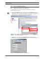
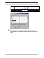
4.2.1
Adding and Configuring the Switchos II
To communicate with the Loading Pump of the Switchos II Advanced
Microcolumn Switching Unit:
a) Start the CHROMELEON server, and then start the CHROMELEON Server
Configuration. Select the name for the server (if more than one is configured)
of which you want to modify the configuration. Click the ‘+’ character in
front of the server name to view its current configuration.
2
1
FIGURE 4-1
The Server Configuration Box
b) Double-click on the ‘LC Packings UltiMate/Switchos’ device (item 2,
FIGURE 4-1).The LC Packings UltiMate/Switchos box appears (FIGURE 4-2).
FIGURE 4-2
4-2
The UltiMate Configuration Box – Components Tab
D850R3
User’s Manual Switchos II
Software Control
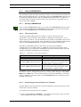
c) Make sure that the SwitchosPump box is checked on the Components tab.
The valves of the Switchos II can either be controlled directly via the
COMMUNICATION connector and via a free COM port of the PC (Section 2.3) or
by the event outputs of the Switchos II Loading Pump via the INPUTS connector
(Section 2.4).
4.2.2
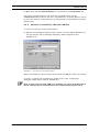
Switchos II controlled by a RS-232 COM Port
To control the unit by serial communication:
a) Add the ‘LC Packings Switchos II SSV’ device to the Timebase (FIGURE 4-1).
This will present the LC Packings Switchos II SSV configuration box
(FIGURE 4-3).
FIGURE 4-3
The Switchos II Configuration Box
Select the COM port which controls the unit and click OK to confirm the setting.
To verify or change the configuration, double-click on the ‘LC Packings
Switchos II SSV’ device (item 2, FIGURE 4-1).
Note: If there are not enough COM ports available, the valves of the Switchos II
can be controlled by the event outputs of the Loading Pump (Section 4.2.3).
User’s Manual Switchos II
D850R3
4-3
Software Control
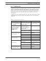
4.2.3
Switchos II controlled by Event Outputs
If serial control is not possible (e.g. no free COM port available), the Switchos
loading pump can be used to control the valve positions. The switching valves
are then controlled by the event outputs of the Switchos II loading pump
(TABLE 4-1) and EVENT8 can be used to trigger another device (e.g. a mass
spectrometer).
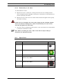
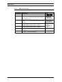
TABLE 4-1
Control Outputs
Switchos II Input
Valve A
Valve B
SSV
Trigger
Loading Pump
EVENT3
EVENT6
EVENT7
EVENT8
Default CHROMELEON Signal Name
Valve_A
Valve_B
SSV
Switchos_Relay2
Note: The EVENT number as well as the type are indicated on the rear panel of
the Micropump (e.g. EVENT 1 'TTL', EVENT 3 'OC', etc.). Make certain that the
proper EVENT output is linked to the corresponding signal name of
CHROMELEON (e.g. ‘Valve_A’ should control EVENT3 of the Micropump, ‘SSV’
should control EVENT7, etc.).
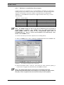
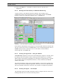
To control the unit by the event outputs of the Loading Pump:
a) Select the Relays tab of the LC Packings UltiMate/Switchos box (FIGURE 4-4).
FIGURE 4-4
The UltiMate Configuration Box – Relays Tab
b) Check the outputs ‘SSV’, ‘Valve_A’, and ‘Valve_B’, check ‘Switchos_Relay_2’
if you want to trigger any instrument by the EVENT 8 output.
Note: The default signal names corresponds to the names used in the
(predefined) panels and should not be changed. If you modify the signal names,
they may not be recognized and some functions may not work properly.
4-4
D850R3
User’s Manual Switchos II
Software Control
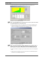
4.2.4
Adding and Configuring the Virtual Channel Driver
To monitor and record various parameters of the UltiMate (e.g. the column
pressure or the oven temperature) a Virtual Channel Driver is needed.
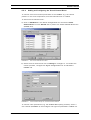
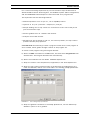
To add a Virtual Channel Driver:
a) Click on Add Device in the Server Configuration box and select Virtual
Channel Driver from the General tab to present the Virtual Channel Driver box
(FIGURE 4-5).
FIGURE 4-5
The Virtual Channel Driver Box
b) Check the first channel and click on Change to configure it. To readout the
column pressure, configure the Signal Configuration box as indicated in
FIGURE 4-6.
FIGURE 4-6
Virtual Channel Setup for Column Pressure Readout
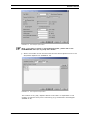
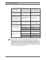
To monitor other parameters (e.g. the UltiMate Micropump pressure), select a
new channel (FIGURE 4-5) and configure the signal as presented in TABLE 4-2.
User’s Manual Switchos II
D850R3
4-5
Software Control
TABLE 4-2
Device
(a)
ULT
ULT
SW II
ULT
FMS
Signal Name and Formula Definitions
Signal Name
Unit
Factor
Formula
PumpPressure
ColumnPressure
TrapColumnPressure
OvenTemperature
TrayTemperature
bar
MPa
psi
1.0
0.1
14.5
°C
1.00
pump.masterpressure
pump.columnpressure
loading_pump.trapcolumnpressure
Oven.Temperature
Sampler.Temperature
Note: a) ULT = UltiMate , FMS = FAMOS , SW II – Switchos II
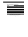
A typical setup is presented FIGURE 4-1.
FIGURE 4-7
Example for a typical Virtual Channel Setup
Note: Make sure to use the same signal names and the same formulas as
indicated in TABLE 4-2. If you modify the signal names or the formulas, they may
not be recognized by the (predefined) panels and some functions may not work
properly.
4-6
D850R3
User’s Manual Switchos II
Software Control
4.3
Using CHROMELEON
The following section provides information how to use the Switchos II Advanced
Microcolumn Switching Unit in conjunction with the CHROMELEON software, the
LC Packings UltiMate system and the FAMOS Microautosampler. In addition to
the steps used to program the Switchos, basic information is provided how to
control the other modules.
4.3.1
l
Starting CHROMELEON
Click on the CHROMELEON Server icon to start the CHROMELEON server (which
is the interface between the CHROMELEON user interface and the instruments).
Click on the CHROMELEON icon to start the software.
4.3.2
The Control Panel
The Control Panel (abbreviated: the ‘panel’) controls and monitors the
instruments of one Timebase. With regard to appearance and function, it is a
special type of window. You can determine the number of available controls and
their functionality via the design tools, depending on your individual requirements
(refer to the CHROMELEON user’s manual for more detailed information).
A number of standard panels for the most commonly used UltiMate
configurations are available. Refer to TABLE 4-3 and choose the panel which
corresponds to your instrument configuration, and then load this panel from the
‘Dionex Templates/ Panels/Dionex LC’ directory.
TABLE 4-3
Panel Name vs. Instrument Configuration
Control Panel Name
Ultimate.pan
Ultimate_FAMOS.pan
Ultimate_FAMOS_Switchos.pan
Ultimate_FAMOS_SwitchosII.pan
Instrument Configuration
UltiMate
UltiMate and FAMOS
UltiMate, FAMOS, Switchos II
(Switchos II valves are controlled by the
Loading Pump – Section 4.2.3)
UltiMate, FAMOS, Switchos II
(Switchos Valves are controlled by serial
communication – Section 4.2.2)
Depending on your authorization, you can create a completely new control panel.
In order to create or change properties of a control panel, change to the Layout
Mode on the Edit menu. A new control panel is saved as a PAN file (*.pan) and
is then available to the user (refer to the CHROMELEON user’s manual for more
detailed information).
4.3.3
Connecting the Control Panel to a Timebase
A panel needs to be connected to a certain Timebase to allow the control of the
instruments of this Timebase.
To connect the control panel to a Timebase:
a) Click on the Connect to Timebase… command on the Control menu to select
the Timebase you want to connect the panel to.
User’s Manual Switchos II
D850R3
4-7
Software Control
b) Use on the Save as… command on the File menu to save this new
assignment.
4.3.4
Starting the Flow Delivery and Baseline Monitoring
To gain control of the different Ultimate modules, each module of the
configuration need to be connected to the control panel. Check the Connect
boxes to connect the individual modules (item 1; FIGURE 4-8).
3
1
1
2
1
1
2
FIGURE 4-8
The Control Panel for UltiMate, FAMOS and Switchos
Flow delivery and baseline monitoring can now be started. Enter the column and
the trap column flow rates in the Flow fields in the corresponding boxes (item 2;
FIGURE 4-8) and click on the blue circle in the toolbar to start baseline
monitoring (item 3; FIGURE 4-8).
4.3.5
Creating a Program File – Using the Wizard
CHROMELEON programs are text files and modifying a program is normally done
by editing in the text window. When creating a new program file, a Program
Wizard starts automatically and guides you through the programming to simplify
the procedure. Enter the required information; in most cases the pre-defined
values can be used.
The wizard provides a ready-to-use program based on your entries, without the
need to type a special programming syntax. Press the F1 key for additional help
and more detailed information. Section 4.3.6 provides a programming example.
4.3.6
Creating a Program – An Example
The following section provides information how to program the flow rate of the
loading pump and how to use the switching valves.
4-8
D850R3
User’s Manual Switchos II
Software Control
For a column switching experiment (a pre-concentration step) the Switchos II
Advanced Microcolumn Switching Unit, the UltiMate system (Nano configuration)
and the FAMOS Microautosampler are used and need to be programmed.
The experiment has the following features:
• NanoLC separation on a 75 µm I.D., 15 cm PepMap column.
• Injection of 10 µl of cytochrom c sample (0.1 pmol/µL).
• Sample loading onto a trap column for 5 minutes at a flow rate of 30 µL/min
(pre-concentration step).
• Solvent gradient from 0 - 50%B in 30 minutes.
• Analysis time of 60 minutes.
• Recording of the UV signal at 214 nm, the column pressure, the trap column
pressure and the pump pressure.
CHROMELEON automatically provides a program wizard when a new program is
to be created, which guides through creation of the program file.
To create a new program using the Program Wizard:
a) Select the New command on the File menu, and then select Program File from
the New box. The Program Wizard starts automatically.
b) Select the Timebase from the Select Timebase Options box.
c) Setup the column oven temperature (if applicable) in the Oven Options box.
d) Setup the trap column pressure limits of the Switchos II Loading Pump (e.g.
0 bar and 200 bar) and fill in the time table in the Loading_Pump Options box.
FIGURE 4-9
The Loading Pump Options Box
e) Setup the gradient conditions in the Pump Options box, use the ‘Multi-step
Gradient’ option to run a gradient.
User’s Manual Switchos II
D850R3
4-9
Software Control
f) Define the gradient in the Flow Gradient Options box FIGURE 4-10).
FIGURE 4-10 The Flow Gradient Options Box
Note: The Flow Gradient box is not present if the ‘isocratic’ option was selected
in the Pump Options box in the previous step.
g) Setup the pressure limits for the separation column and the UltiMate pump,
and define separation column parameters (e.g. I.D., length and stationary
phase) in the UltiMate Pump Options box (FIGURE 4-11).
FIGURE 4-11 The UltiMate Pump Options Box
Note: If you do not specify the ‘Column’ parameters (e.g. the option ‘other’ is
selected), you need to enter a CRP (Column Resistance Parameter) value. The
CRP is required to calculate the (master) flow rate of the UltiMate Micropump.
h) Specify the detector settings (e.g. the data collection rate) in the UV Options
box.
i) Define the type of injection you want to use and the corresponding injection
parameters in the Sampler Options box.
4-10
D850R3
User’s Manual Switchos II
Software Control
4
FIGURE 3-12 The Sampler Options Box
Note: If you want to create a ‘User Defined Program’, please refer to the
CHROMELEON online (F1 key) help more details.
j) Select the number of UV channels used and the data acquisition time in the
Acquisition Options box (FIGURE 4-13).
FIGURE 4-13 The Acquisition Option Box
The number of UV_VIS_n Options boxes to be filled in is dependent on the
number of channels that you are monitoring (e.g. the different wavelengths
(FIGURE 4-14).
User’s Manual Switchos II
D850R3
4-11
Software Control
FIGURE 4-14 The UV_VIS_n Options Box
k) Specify the program name and path.
Note: The Appendix E of the user’s manual of the UltiMate system presents 4
additional examples.
4.3.7
Changing a Program File
A CHROMELEON program can easily be changed by a double click on the
program name in the CHROMELEON browser. The program appears in a text
format. Program lines are inserted by describing the parameter or by using the F8
command.
4-12
D850R3
User’s Manual Switchos II
Testing the Switchos
CHAPTER 5
5.1 Overview
This chapter describes a series of activities that can be used to check the
operation of the system and to verify that your Switchos Advanced Microcolumn
Switching Unit is operating in an acceptable manner.
This chapter includes:
•
Testing the Solvent Bottle Caps and Degassing Unit (Section 5.2.1).
•
Testing for the Solvent Selection Valve (Section 5.2.2).
•
Testing of the fluid path for the Solvent Selection Valve and solvent lines
(Section 5.2.3).
•
Testing of the Switching Valves (Section 5.2.4).
Note: Unless otherwise noted, pure methanol should be used as the solvent and
these tests should be performed at 25oC.
User’s Manual Switchos
D850R3
5-1
Testing the Switchos
5.2 Checking System Components
5.2.1 Solvent Bottle Caps and Degassing Unit
The He lines, the regulating valve and connections can be tested by the following
procedure:
a) Close the Shut-Off Valves (FIGURE 5-1) and apply 3 bar (45 PSI) of He
pressure.
CAUTION
Caution: Do not operate the He lines a higher pressure than 4 bar (60 PSI).
Vent
He Shut-Off
Valve
FIGURE 5-1. The He Shut-Off Valve (Opened Position)
b) Open the He Regulating Valve on the front panel. The regulating valve should
be turned 90o. Check to see if there are any leaks (i.e. are He bubbles
observed in the solvent bottle).
c) Open the shut-off valve on the bottle cap for solvent bottle A, by closing the
He regulating valve verify that the bubbles of He exit on the side frit of the
sparging/filter frit. Check to make sure that it is possible to regulate the He
flow by opening the He regulating valves until the maximum is reached (90o).
d) Repeat steps (b) and (c) for each solvent bottle.
5.2.2 Solvent Selection Valve – Basic Test
To check the operation of the Solvent Selection Valve and the Valve Controller:
a) Set the Switchos in local mode by the Remote/Local switch on the back
panel (the LEDs of the two push buttons on the front panel should be
illuminated).
b) Select the next available solvent channel by the SSV button. The
corresponding LED should be illuminated and the sound of the moving
solvent selection valve should be heard for a few seconds.
c) Repeat step (a) for each solvent channel.
5-2
D850R3
User’s Manual Switchos
Testing the Switchos
5.2.3 Solvent Selection Valve and Solvent Lines – Fluid Path Test
To determine if the fluidic path for solvent line is operating properly and if the
resistance of the flow path is within the specifications:
a) Fill each solvent bottle (with methanol) until the fluid level corresponds to the
top of the Switchos housing.
b) Open the four He shut-off valves on the bottle cap assemblies to open the
solvent lines (the He supply line has to be shut off for this test).
c) The four solvent lines should be well flushed using the Purge function of the
loading pump. If is not possible to flush the lines, check for clogged or dirty
solvent filters (sparging/filter frits) or bent solvent lines.
d) Switch the flow delivery of the loading pump off, disconnect the solvent inlet
line from the pump head and connect a 250 µL syringe (i.e. the plunger
should be removed) using an adapter (P/N 160259) as shown in FIGURE 5-2.
FIGURE 5-2. Placing the Syringe on the Solvent Inlet Line
e) Select solvent channel A by the SSV button on the rear of the Switchos. The
LED corresponding to Valve A should be illuminated.
f)
Measure the flow rate from the inlet tubing for one minute. The flow rate
should be greater than 50 µL/min for a solvent line that is functioning
properly.
g) Repeat steps (e) and (f) for each solvent line.
Note: If the flow is less than the specified value, repeat the test with the solvent
filters removed. If the flow is within specifications after the filters have been
removed, they are clogged, dirty or defective and must be replaced.
Note: As an alternative to using a syringe, this test can be performed by allowing
the solvent to drip from the solvent inlet line and counting the number of drops
per minute. At least 5 drops per minute should be observed if the proportioning
valve opens properly. If the flow rate is less than 5 drops/min, repeat the test
with the solvent filters removed. If the flow is within specifications after the
filters have been removed, the filters are clogged, dirty or defective and must be
replaced.
User’s Manual Switchos
D850R3
5-3
Testing the Switchos
5.2.4 Switching Valves – Basic Test
To check the basic function of the Switching Valves and the Valve Controller:
a) Set the Switchos in local mode by the Remote/Local switch on the back
panel. The LEDs of the two push buttons on the front panel should be
illuminated.
b) Toggle valve A by the corresponding push button on the front panel. The LED
corresponding to the current position (e.g. LED 1-2 or LED 10-1) should be
illuminated and you should hear the sound of the moving valve for a short
period of time.
c) Repeat step (b) for switching valve B.
5-4
D850R3
User’s Manual Switchos
Maintenance and
Troubleshooting
CHAPTER 6
6.1
Overview
This chapter provides information to assist in optimizing the performance of the
Switchos Advanced Microcolumn Switching Unit and maintaining it in your
laboratory. It includes the following material:
•
Maintenance - describes a series of activities that should be performed on a
periodic basis to optimize the performance of the system and minimize down
time (Section 6.2).
•
Replacing Components – provides directions for replacing components, e.g.
due to wear (Section 6.3).
•
Troubleshooting - discusses a series of activities that should be used to
determine the cause of a problem. (Section 6.4).
•
Spare Parts/Replacement Parts Lists – Presents a listing of components that
are used to maintain the unit or to change the configuration (Section 6.5).
User’s Manual Switchos II
D850R3
6-1
Maintenance and Troubleshooting
6.2
Maintenance
Maintenance refers to a variety of activities that should be performed on a
routine basis to optimize performance of the system. Many routine maintenance
activities can be readily performed by the user. Detailed information about the
maintenance of the Switchos Loading Pump is presented in the ‘UltiMate
Micropump User’s Manual’.
In some cases (e.g. replacement of critical components), we recommend that a
factory trained service engineer should be called to perform the operation. This
will ensure optimal long term performance and maximum uptime. LC Packings
provides a broad range of service support activities to ensure that the Switchos
Advanced Microcolumn Switching Unit is functioning in a suitable manner. These
activities can be customized to meet the specific needs of the customer. For
further information, please contact your local LC Packings office or
representative.
TABLE 6-1. Recommended Maintenance Schedule
Frequency
Every Day
Every 3 months
Every year
Operation
Before operating, check for any air bubbles in
the fluidic lines and degas the solvent.
Check that the fluidics connections do not leak.
Check that salts are not deposited by the
fluidics joints.
When using buffer solutions, flush the system
thoroughly after use with a solvent that does
not contain buffers/salts.
Inspect the condition of all tubing (cracks, nicks,
cuts, clogging).
Replace:
Rotor seal of the switching valves
Check:
Stator of the switching valves
Solvent Selection Valve for Leakage a)
a) Contact your LC Packings representative.
Note: The frequency of the various activities described above is a reasonable
starting point. As the user gains experience with the system, it will be found that
some activities can be done less frequently and other need to be done more
frequently. The frequency is dependent on a number of factors including the
nature of the sample and the mobile phase.
6-2
D850R3
User’s Manual Switchos II
Maintenance and Troubleshooting
6.3
Replacing Major Components
A variety of components on the Switchos Advanced Microcolumn Switching Unit
can be readily changed by the user as required to ensure that the instrument is
maintained in optimal condition.
This section provides information and procedures about how to replace user
replaceable parts. In most cases, re-assembly of a component is identical to its
disassembly, except that the steps are performed in the reverse order. If no
comment is made, it should be assumed that the assembly of a component or
installation of a component is identical to disassembly or removal, except that
the actions are in the reverse order.
Sections 6.3.3 to 6.3.5 provide basic information about how to remove the
pump head and how to replace check valves cartridges or piston seals. For more
detailed information refer to the ‘UltiMate Micropump User’s Manual’.
6.3.1 Replacing the Sparging/Filter Frit
The Sparging/Filter Unit is connected via tubing which slides off the unit. Over
time, the filter may become clogged by particulate matter and should be
replaced. In some cases, the filter can be cleaned via an ultrasonic bath
(depending on the nature of the particulate matter).
Note: A clogged filter may lead to poor analytical performance (Section 6.4 Troubleshooting).
To replace the Sparging/Filter Frit:
a) Unscrew the Solvent Bottle Caps from the solvent bottles and take the
tubing with the frit out.
b) Remove the old frit by pulling the tubing (item 1, FIGURE 6-1) off the filter
body (item 2, FIGURE 6-1).
c) Insert the He tubing and the solvent tubing into a new Sparging/Filter Frit
(P/N 160044). The He tubing should be placed in the hole closer to the He
outlet.
d) Gently pull at each line to make sure that it is secure.
1
Solvent Line
He Line
He Outlet
(Top View)
2
Solvent Inlet
FIGURE 6-1. Sparging/Filter Frit
User’s Manual Switchos II
D850R3
6-3
Maintenance and Troubleshooting
6.3.2 Replacing the High Pressure In-line Filter
The high pressure in-line filter serves to remove particulate matter from the
mobile phase and is considered as a consumable item. If excessive pressure is
required to deliver the mobile phase (indicated on the pump display), it is
probable that the filter should be replaced.
To replace the high pressure in-line filter:
e) Remove the capillary (item 1, FIGURE 6-2) between the purge valve and the
filter unit.
1
2
FIGURE 6-2. High Pressure Inline Filter
f)
Use the socket driver (P/N 160073) or a wrench (11 mm) to remove the filter
holder (item 2, FIGURE 6-2).
g) Remove the filter and place a new filter into the holder (FIGURE 6-3).
Filter
Description
Filter
Standard (color: black)
Inert
(color: blue)
Filter Frit Holder
Standard (stainless steel)
Inert
(titanium)
P/N
160072
161107
163021
162108
FIGURE 6-3. In-Line Filter in Filter Holder
h) Re-mount the filter holder.
CAUTION
6-4
Caution: Make certain that the filter remains in the filter holder when screwing
the holder in and do not overtighten the filter holder. Overtightening could result
in distortion of the filter which may lead to leakage and/or premature failure of
the component.
D850R3
User’s Manual Switchos II
Maintenance and Troubleshooting
6.3.3 Removing the Pump Head
To remove the Pump Head:
a) Remove the inlet and the connecting capillary (FIGURE 6-4).
2
3
4
5
1
FIGURE 6-4. Disassembly of the Pump Head
b) Loosen two diagonally opposed screws (e.g. screws ‘2’ and ‘4’ in FIGURE 64 by a quarter turn at a time and remove the screws.
c) Carefully loosen the two remaining screws (e.g. screws ‘3’ and ‘5’ in FIGURE
6-4), alternating from one to the other, approximately half a turn at a time
and remove the screws.
d) Remove the pump head.
Note: If the purpose of removing the pump head is to check the piston rods,
there is no need to disassemble the pump head any further. Pull out each piston
rod in a straight line using a pair of pliers.
To replace the Pump Head:
a) Position the pump head onto the housing and carefully line up the screw
holes. Tighten all four set screws by hand.
b) Alternating from one to the next, tighten two diagonally opposed screws
(e.g. screws ‘2’ and ‘3’) half a turn at a time until the pump head is correctly
seated onto the housing.
c) Tighten the two other screws.
d) Check that the screws that were tightened in step c) are well tightened.
User’s Manual Switchos II
D850R3
6-5
Maintenance and Troubleshooting
6.3.4 Disassembling the Pump Head/Replacing Piston Seals
To disassemble the inert pump head (titanium inlays):
a) Remove the pump head and the piston rods (Section 6.3.3).
3
17
18
6
5
4
7
11
15
2
14
1
13
Detail of ‘13’
12
16
10
Flow
9
8
13
14
15
Item
1
2
3
4
5
6
7
8
9
10
11
12
13
14
15
16
17
18
Orientation Mark
Description
Inert Pump Head
Recessed-Head Screw
Retaining Plate
Piston Rod
Guide for Spring
Spring
Spacing Bolt
Support Washer
Piston Seal (backflushing)
Pressure Plate
O-Ring
Piston Seal (high pressure)
Titanium Inlay
Check Valve Cartridge
PEEK Adapter
Check Valve Bushing
Set Screw
Backflushing Connection
Connecting Tubing Pump Head
Notes:
1)
2)
3)
P/N
161399
160047
161020
160084
161020
161400
160049
162300
161071
-
1
1
162010
161023
2
3
Stainless steel
Titanium
Set of 4 piston seals (includes two high pressure seals and two
backflushing seals)
Used with the standard (stainless steel) version of the Switchos only.
Used with the inert version of the Switchos only.
FIGURE 6-5. The Inert Pump Head Assembly
b) Loosen the two screws that attach the retaining plate to the pump head
(items 1, 2; FIGURE 6-5). As you remove the screws, alternate from one to
the other as long as the springs are loaded to avoid damaging the retaining
plate.
Note: Since the springs (item 5; FIGURE 6-5) exert a significant amount of force,
care should be taken when the screws are loosened.
6-6
D850R3
User’s Manual Switchos II
Maintenance and Troubleshooting
c) Remove the spring guides, the springs and the support washers (items 4, 5,
7; FIGURE 6-5).
d) You can remove/replace the piston seals (backflushing seals) now. Use an
appropriate tool (e.g. a small screwdriver) to remove the seals (item 8;
FIGURE 6-5).
e) Loosen the spacing bolts (item 6; FIGURE 6-5). Remove the two spacing
bolts and then remove the pressure plate (item 9; FIGURE 6-5).
f)
You can remove/replace the piston seals (high pressure seals) now. Use an
appropriate tool (e.g. a small screwdriver) to remove the seals (item 11;
FIGURE 6-5).
Note: The seals should only be replaced when the pump leaks. The useful
lifetime depends on the mobile phase to be pumped and the back pressure of the
system. The typical lifetime of the seals is in the order of 2500 h. It is
recommended that both seals be replaced if one is defective.
g) To remove the titanium inlays, remove the four bushings, the check valves
and the PEEK adapters (items 13, 14, 15; FIGURE 6-5).
h) Carefully insert new seals. The spring side should be placed as indicated in
FIGURE 6-5.
To re-assemble the pump head:
a) Insert the titanium inlays, the two check valve cartridges (item 13; FIGURE
6-5) and the two PEEK adapters (item 14; FIGURE 6-5). As you replace the
check valves, make certain that they are inserted in the right position.
CAUTION
Caution: Make certain that the orientation mark of the check valve cartridges is
placed so that the mark is on the bottom. Installing the check valve cartridges in
the wrong direction may lead to a damage of a cartridge or the pump head.
b) Alternating from one to the next tighten the upper and the lower bushing half
a turn at a time by hand.
c) Replace the pressure plate with the 2 o-rings (items 9, 10; FIGURE 6-5) and
the two spacing bolts (items 9, 10; FIGURE 6-5). Alternating from one to the
next tighten the two bolts by hand.
d) Tighten the two bolts, and then tighten the 4 bushings. Make certain that all
screws are securely tightened.
6.3.5 Replacing the Check Valve Cartridge
The inert pump head is equipped with two check valves (item 13; FIGURE 6-5),
one on the inlet side of the main piston (lower right) and on the outlet of the
main piston (upper right) while two PEEK adapters are used on the auxiliary
piston (lower and upper left side).
User’s Manual Switchos II
D850R3
6-7
Maintenance and Troubleshooting
To remove/clean the check valves cartridge(s):
a) Unscrew the two check valve bushings (items 15, FIGURE 6-5) and remove
the check valve cartridges.
b) As you replace the check valves, make certain that they are inserted in the
right position (item 13; FIGURE 6-5). Tighten the two check valve bushings
by hand.
c) Alternating from one to the next, tighten the upper and the lower bushing
half a turn at a time.
d) Tighten the two check valve bushings.
CAUTION
Caution: Make certain that the orientation mark on each check valve is placed so
that the mark is on the bottom. Installing the check valves in the wrong direction
may lead to a damage of the pump head.
6.3.6 Removing the Side Panels
The side panels must be removed to gain access to remove the loading pump
and to access the Solvent Selection Valve.
To remove the panels:
a) Remove three screws on the back of each side panel (items 1-6, FIGURE 66).
1
4
2
5
3
6
FIGURE 6-6. Rear View of Switchos
b) Remove the side panels.
6-8
D850R3
User’s Manual Switchos II
Maintenance and Troubleshooting
6.3.7 Removing the Loading Pump
To remove the Micropump:
a) Disconnect all cables on the rear panel of loading pump.
b) Remove the capillary inlet and outlet connections from the loading pump.
c) Remove the side panels of the Switchos (Section 6.3.6).
d) Remove the two screws on the left side and the two screws on the right of
the loading pump.
e) Remove the loading pump from the front of the Switchos.
CAUTION
Caution: When removing the loading pump from the Switchos, carefully pull the
devices out of the housing. To avoid any damage to the component, make
certain that it is not allowed to drop as it is being removed from the housing.
Note: When re-installing the instrument, take care that the mobile phase tubing is
not bent or overly flexed.
6.3.8 Cleaning the 10-Port Switching Valve
Cleaning the 10-port valve can often be accomplished by flushing all the lines
with an appropriate solvent(s). The selection of the solvent is dependent on the
nature of the sample and the mobile phases that are used. Solvents such as
methanol, acetonitrile, methanol/water (80/20) or acetonitrile/water (80/20) are
normally used to clean the valve. See Appendix A for instructions about
disassembling/assembling, cleaning and maintenance of the switching valve.
User’s Manual Switchos II
D850R3
6-9
Maintenance and Troubleshooting
6.3.9 Replacing the Main Fuse
DANGER
Danger: Disconnect the instrument from the mains before inspecting/changing
the fuse.
To change the Fuse:
a) Pull out the fuse holder (item 1, FIGURE 6-7).
Fuse
FIGURE 6-7. The Fuse Compartment
b) Replace the blown fuse by a fuse of identical rating (2 A, Slo Blo fuse).
c) Re-install the fuse holder.
6-10
D850R3
User’s Manual Switchos II
Maintenance and Troubleshooting
6.4
Troubleshooting
Troubleshooting refers to the determination of the cause of a problem. Since the
Switchos Advanced Microcolumn Switching Unit is incorporated into an HPLC
system, the first step to determine if the problem is due to this instrument is to
remove the unit from the system, then perform an injection and compare the
results from the two runs. If the results are fine, the problem is due to the
switching unit.
In addition, the typical system parameters (e.g. flow rates and pressure) of a preconcentration setup with trap column and separation column are presented in
TABLE 6-3
TABLE 6-1 Troubleshooting the Loading Pump
Problem
Probable Cause
Solution
Flow delivery stops after 1
minute during purging, error
message ”Minimum pressure
...“ is displayed
System pressure dropped
below the minimum pressure
(Pmin) set in SETUP menu
PRESSURE LIMITS
Set “min” value to 0 MPa
to disable checking
Flow delivery stops during
purging, error message
„Maximum pressure
exceeded nn MPa“ is
displayed
No solvent delivery, pump
motor is running
Leaking pump head
System pressure exceeded
the maximum pressure
(Pmax) set in SETUP menu
PRESSURE LIMITS or in
monitor screen
Open the purge valve knob
Note: The pressure during
purging is limited to 0.5 MPa.
Air in solvent/pump head
Purge pump and check
degassing
Clogged solvent inlet filter
Replace solvent inlet filter
Leakage in the pump head
Check for any leakage
Loose inlet/ outlet fitting
Tighten the fittings
Loose check valve(s)
Tighten the check valves
Defective piston seals
Replace seals
Flow restriction in the solvent Check tubing, filters,
inlet fluid path
proportioning valves, etc.
Flow fluctuation
Flow rate too high or too
low (deviation >10%)
User’s Manual Switchos II
Air in solvent inlet fluid path
Purge pump, check
degassing
Defective valves
Clean/replace check valves
Air in solvent inlet fluid path
Purge pump, check
degassing
Pump out of calibration
Contact LC Packings
D850R3
6-11
Maintenance and Troubleshooting
TABLE 6-2 Troubleshooting the Switching Valves
The Switchos does not
respond to any signal
applied to the INPUTS
connector
The Switchos is in LOCAL
mode, e.g. the LEDs in the
push buttons are illuminated
Change control mode to
REMOTE (REMOTE/LOCAL
switch on the rear panel)
The switching valves do not
respond when pressing the
controls (push buttons on
front/rear panel)
The Switchos is in REMOTE
control mode, e.g. the LEDs
in the push buttons are not
illuminated
Change control mode to
LOCAL (REMOTE/LOCAL
switch on the rear panel)
The Solvent Selection valve
moves to the next solvent
channel, and after a short
moment it moves back to
channel A (REMOTE control
mode)
The signal applied to the
SSV input has been active
for longer 1.5 sec
Apply a shorter signal
(< 1.5 seconds)
The valve A (B) switches to
position 1-2 as soon as the
instrument is set into
REMOTE control mode
At the present time there is
no active input signal and
the valve is forced into
position 1-2
Change the setting of the
instrument controlling
Switchos according to the
needs of the application
The Switching Valve A (B)
does not switch…
Switch OFF the instrument
and ON again to reset the
error
due to valve sticking, …
Clean Valve
clamp ring slippage,..
Tighten clamp ring
other positioning problems
Contact LC Packings
The Solvent Selection Valve
does not switch…
Switch OFF the instrument
and ON again to reset the
error
due to valve sticking, …
Contact LC Packings
clamp ring slippage,..
Contact LC Packings
other positioning problem
Contact LC Packings
LEDs 1-2 and 10-1 of Valve
A (B) are switched off or
switched on at the same
time
LED A-D illuminated at the
same time
Note: It is important to note that many analytical problems are be caused by
external influences such as the temperature and or the analysis of light sensitive
samples and are not instrument related. When troubleshooting, make certain that
the application was running in an acceptable fashion before the problems were
observed and that nothing has been changed in the application. If you are making
a change in the protocol, change a single parameter at a time and ensure that the
effect of each change is well understood.
6-12
D850R3
User’s Manual Switchos II
Maintenance and Troubleshooting
TABLE 6-3 Typical System Parameters of a Pre-concentration Setup
Parameter
Micropump Flow
(Master flow)
Micropump Pressure
(Master pressure)
CRP
(b)
Column Flow
Column Pressure
Trap Column Flow
Trap Column Pressure
Connecting Tubing I.D.
(c)
Response (delay) Time
‘Injection to injection peak’ (d)
He pressure
Notes:
Typical values (a)
CAP Configuration
NAN Configuration
200 µL/min
187.5 µL/min
160 – 200 bar
160 – 200 bar
50
4 µL/min
60 – 80 bar
30 µL /min
40 – 70 bar
625
300 nL/min
100 – 130 bar
30 µL /min
40 – 70 bar
50 µm
20 µm
2 -5 min
2 – 5 min
1 bar
1 bar
a) 100 % mobile phase A (start condition of the UltiMate standard system
checkout procedure with the cytochrome c test sample).
b) No flow sensor for automatic CRP calibration used.
c) Used in the micro flow path.
d) If a trap column is used in conjunction with the Switchos, this is the
time after switching the trap column into the micro flow.
User’s Manual Switchos II
D850R3
6-13
Maintenance and Troubleshooting
6.5
Spare Parts Lists
Note: Please refer to the ‘User’s Manual UltiMate Micropump’ for the lists of
spare parts for the Micropump.
6.5.1 Major Items
Part Number
163662 a
160170 b
163663
160559
a
b
Notes:
Description
Switchos™ Microcolumn Switching Module, consists of 1x loading
pump, 2x 10-port valves and 1x solvent selection
Switchos™ Microcolumn Switching Module, INERT Version,
consists of 1x loading pump, 2x 10-port valves and 1x solvent
selection valve
a) Instrument equipped with a blue LC Display
b) Instrument equipped with a green/yellow LC Display
6.5.2 Tubing, Fittings and Bottles
Part Number
160180
160181
160174
160175
162015
160183
161470
160483
160173
160492
160266
161000
161007
163915
161479
161480
160182
Description
130 µm I.D. x 50 cm PEEK tubing, set of 2 pieces
130 µm I.D. x 100 cm PEEK tubing, set of 2 pieces
250 ml (safety) solvent bottle
Caps for solvent bottles, set of 6 pieces
Bottle cap assembly
3 meter Helium supply tubing, 6 mm O.D.
T-piece for Helium tubing
Capillary cutter
1/16” universal fingertight fitting, one-piece design, extra long
body,4 pieces
PEEK sleeves, precision cut and polished for connections with
fused silica tubing (300 µm O.D.) set of 5 pieces
Set of 20 nuts and ferrules for Valco switching valves
PEEK Fingertight nuts and ferrules for inert injection/switching
valves, set of 10
PEEK Hex nuts and ferrules for inert injection/switching valves, set
of 10
PEEK ferrules with groove, for inert valves (20 pcs)
Capillary LC – Standard Version
50 µm I.D. Connecting tubing, Switchos to UltiMate injection
valve, 70 cm length
50 µm I.D. Connecting tubing, Switchos to UltiMate column
compartment, length 50 cm, includes union
30 µm I.D. PEEK shielded fused silica connection tubing µPrecolumn™/Valve
Nano LC – Standard Version
160178
160179
160182
20 µm I.D. Connecting tubing, Switchos to UltiMate injection
valve, length 65 cm
20 µm I.D. Connecting tubing, Switchos to UltiMate column
compartment, length 50 cm, includes union
30 µm I.D. PEEK shielded fused silica connection tubing µPrecolumn™/Valve
Capillary LC – Inert Version
161261
161262
160182
6-14
50 µm I.D. Connecting tubing, Switchos to UltiMate injection
valve, 70 cm length
50 µm I.D. Connecting tubing, Switchos to UltiMate column
compartment, length 50 cm, includes union
30 µm I.D. PEEK shielded fused silica connection tubing µ-
D850R3
User’s Manual Switchos II
Maintenance and Troubleshooting
Precolumn™/Valve
Nano LC – Inert Version
161259
161260
160182
20 µm I.D. Connecting tubing, Switchos to UltiMate injection
valve, length 20 cm – inert version
20 µm I.D. Connecting tubing, Switchos to UltiMate column
compartment, length 50 cm, includes union – inert version
30 µm I.D. PEEK shielded fused silica connection tubing µPrecolumn™/Valve
6.5.3 10-port valve
Part Number
161472
162016
Description
Standard Version (Stainless Steel)
Replacement rotor for VALCO C2, 10-Port
Stator VALCO C2, 10-Port
Inert Version (PAEK)
161005
161006
Note:
Replacement rotor for VALCO C2, 10-Port valve – inert version
PAEK Stator VALCO C2, 10-Port valve, inert version
PAEK = Polyaryletherketone, PEEK = Polyetheretherketone
6.5.4 Filters/Tools
Part Number
160044
160073
160259
Description
He Sparging/Filter Frit
Socket driver 11mm, for In-line filter replacement
Syringe adapter for Valco switching valves
Standard Version
160177
161001
0.5 µm replacement in-line filter frit
Frit Holder
Inert Version
161107
162014
0.5 µm replacement in-line filter frit – inert version
Frit Holder, Titanium – inert version
6.5.5 Trap Columns and Column Accessories
Part Number
160461
160431
160432
Description
Nano trap column holder, 1mm
Micro trap column holder, 5mm
Micro trap column holder, 15mm
Micro Trap Columns
160454
160446
160450
300 µm I.D. x 5 mm, packed with 5 µm C18, 100Å, PepMap™,
set of 5 cartridges
500 µm
set of 5
500 µm
set of 5
I.D. x 5 mm, packed with 5 µm C18, 100Å, PepMap™,
cartridges
I.D. x 15 mm, packed with 5 µm C18, 100Å, PepMap™,
cartridges
Nano Trap Columns
160458
Note:
300 µm I.D. x 1 mm, packed with 5 µm C18 100Å PepMap™, set
of 5 cartridges
Please refer to our web-site for more detailed information on
stationary phases and column dimensions available
(www.lcpackings.com).
6.5.6 Pump Head and Tubing - Inert Pump Head (Titanium Inlays)
Part Number
161399
160049
160050
User’s Manual Switchos II
Description
Inert Pump Head (Titanium Inlays)
Check Valve Cartridge (1 piece)
Check Valve Cartridges (set of 5)
D850R3
6-15
Maintenance and Troubleshooting
161020
160047
161400
162300
160084
161026
Piston Seals [Graphite Fibre Filled PTFE],
1/4” O.D. and 0.315” O.D. (set of 4)
Sapphire Piston
Titanium Inlay for the Inert Pump Head
PEEK Adapter for inert Pump Head
O-Ring, 17 mm x 1.5 mm
Torque Wrench
Connecting Tubing for the Switchos - Inert Version
161024
161023
161022
160053
Connecting Tubing Pressure Sensor to
High Pressure Filter, Titanium [1]
Connecting Tubing for Pump Head,
Titanium [2]
Connecting Tubing Pump Outlet to
Pressure Sensor, Titanium [3]
PEEK Connecting Tubing Pump Inlet [4]
2
1
4
3
Connecting Tubing for the Switchos - Standard Version
160056
162010
162009
160053
Note:
Connecting Tubing Pressure Sensor to
High Pressure Filter, Stainless Steel [1]
Connecting Tubing for Pump Head,
Stainless Steel [2]
Connecting Tubing Pump Outlet to
Pressure Sensor, Stainless Steel [3]
PEEK Connecting Tubing Pump Inlet [4]
2
1
4
3
The ‘Inert’ and the ‘Standard’ system use the same type of pump
head, but different connecting tubing.
6.5.7 Control Cables
Part Number
Description
9 pin
female
9 pin
female
160069
Y-Communication cable
160070
Serial Communication Cable
160071
Solvent Organizer Communication Cable
160147
Contact Closure (4x) Cable for FAMOS P5
160171
Cable for controlling Switchos by FAMOS P5
Auxiliaries
160172
Cable for controlling Switchos by UltiMate
Event Outputs
160184
Set of Connectors (WAGO Type)
9 pin
male
9 pin
female
9 pin
male
1:1
1x
1x
6-16
D850R3
1x
1x
User’s Manual Switchos II
Specifications
CHAPTER 7
7.1
Analytical Specifications
7.1.1 10-Port Switching Valves
Type
Max. Pressure
Wetted Surfaces
Flow Passage
Diameter
Switching time
Operation
Position Indicator
low dispersion 10-port valve, 2x
350 bar (5000 psi)
standard version
stator:
stainless steel
rotor:
Valcon H
0.15 mm
inert version
PAEK
Valcon E
< 100 ms
local control (push button),
remote control (relay, open collector or TTL)
two LEDs per valve
7.1.2 Solvent Selection Valve
Wetted Surfaces
Switching Time
Position Indicator
stator: PPS (polyphenylene sulfide)
rotor: Valcon E2
< 165 ms (channel to channel)
four LEDs
7.1.3 Loading Pump
Pump Type
Flow Rate Range
reciprocating double piston pump
10 - 500 µL/min
Flow Rate
Accuracy
Pressure Range
Pressure
Monitoring
Rapid Purge Valve
Instrument
Control
< 0.5%
User’s Manual Switchos II
0 - 400 bar
indication of µ-column pressure
yes
CHROMELEON® software or standalone
D850R3
7-1
Specifications
7.2
General
7.2.1 Physical
Dimensions
(WxDxH)
Weight
185 mm (7.3 in) x 350 mm (13.8 in) x 430 mm (16.9 in).
16 kg (35 lbs.).
7.2.2 Electrical
Power
Requirements
Fuse
INPUTS
(VALVE A,
VALVE B,
SSV)
90 - 260 V, 47 - 62 Hz, 100 VA
2x Slow-Blow, 2A
Input resistance:
max. Voltage ‘Input inactive’
min. Voltage ‘Input’ active
10 kΩ
0.5 V
2.0 V
absolute maximum ratings:
min. voltage:
max. voltage:
-0.3 V
5,3 V
Note: Maximum ratings are the extreme limits the input pin can be exposed
to without causing permanent damage. Do NOT connect voltages
lower/higher than those limits.
7.2.3 Communication
by RS-232 serial communication
Switching Valve or
by relay, open collector or TTL outputs
A and B
(e.g., from FAMOS or UltiMate Micropump)
by RS-232 serial communication
Solvent
or
Selection valve
by relay, open collector or TTL outputs
(e.g., from FAMOS or UltiMate Micropump)
Loading Pump
by RS-232 serial communication network
7.3
Inert Version
(factory
installed)
Flow Passage
Diameter
7-2
Options
all fluidic pathways made out of inert materials,
i.e. PAEK, PEEK, PTFE, ceramic, titanium
0.25 mm
D850R3
User’s Manual Switchos II
Switching Valves
APPENDIX A
A.1
Overview
The LC Packings Switchos II Advanced Microcolumn Switching Unit is equipped
with two Cheminert® Model C2 10-Port Column Switching Valves manufactured
by VICI™ Valco Instruments Co. Inc. These valves are designed to offer optimal
results with the switching system as they are made from materials that are inert
to materials used in liquid chromatography and are designed to provide
exceedingly low carryover when switched.
Note: A detailed discussion on the Installation, Use and Maintenance of the valve
is presented in Technical Note 801 from VICI Valco Instruments, Co. Inc. and
can be obtained at the Valco website (www.Valco.com)
User’s Manual Switchos II
D850R3
A-1
The Switching Valves
A.2
Maintenance
In most instances, the only maintenance that is required is cleaning of the valve.
Cleaning can often be accomplished by flushing all the lines with an appropriate
solvent(s). The selection of the solvent is dependent on the nature of the sample
and the mobile phases that are used. Typically solvents such as methanol,
acetonitrile, methanol/water (80/20) or acetonitrile/water (80/20) should be
used.
A.3
Disassembly/Reassembly of the Valve
Note: Do not disassemble the valve unless system malfunction is definitely
isolated to the valve.
A.3.1
Disassembly of the Valve
To disassemble the valve:
a) Use a 9/64” hex driver to remove the socket head screws which secure the
cap to the valve (FIGURE A-1)
Driver
Rotor
Stator
FIGURE A-1. Exploded View of the Valco Model C2 Valve (6-port Version)
b) To insure that the sealing surface of the cap is not damaged, rest it on its
outer face. If the tubing is still attached, leave it suspended by the tubing.
c) Gently pry the rotor away from the driver with your fingers or a small
screwdriver.
d) Examine the rotor sealing surface for scratches.
•
If scratches are visible to the naked eye, the rotor must be replaced.
•
If no scratches are visible, clean all parts thoroughly with an
appropriate solvent. Take care that no surfaces get scratched while
you are cleaning the components.
Note: The most common problem in the use of the valve with HPLC is the
formation of buffer crystals, which are usually water-soluble. After cleaning, it is
not necessary to dry the rotor.
A-2
D850R3
User’s Manual Switchos II
The Switching Valves
A.3.2
Reassembly of the Valve
To reassemble the valve:
a) Replace the rotor in the driver, making sure that the rotor sealing surface
with its engraved flow passages is facing out. The pattern is asymmetrical to
prevent improper placement.
b) Replace the cap. Insert the two socket head screws and tighten them gently
until both are snug.
CAUTION
Caution: Do not overtighten the screws-they simply hold the assembly together
and do not affect the sealing force, which is automatically set as the screws
close the cap against the valve body.
c) Test the valve by pressurizing the system. If the valve does not hold pressure
it should be returned for repair.
Note: When re-installing the valve, make certain that the proper tubing is
attached to the appropriate fitting.
A.4
Spare Parts
Part Number
161472
Description
Standard Version (Stainless Steel)
Replacement rotor for VALCO C2, 10-Port
162016
Stator VALCO C2, 10-Port
161005
Inert Version (PAEK)
Rotor for Switchos™, 10-port injection valve
(VALCO C2), INERT
161006
Figure
PAEK Stator for SWITCHOS™ 10-port valve
(VALCO C2), INERT
Note: PAEK = Polyaryletherketone
User’s Manual Switchos II
D850R3
A-3
The Switching Valves
[This page intentionally left blank]
A-4
D850R3
User’s Manual Switchos II
Network Identification
APPENDIX B
B.1
Identifying the Switchos on the Network
The Device Identifier and Serial Number of the Switchos Advanced Microcolumn
Switching Unit must be correctly set to ensure proper operation of the unit on
the network.
The Device Identifier and Serial Number is factory set during the manufacturing
process. It can be checked in the GLP Menu.
If it becomes necessary to reset the Device Identifier and/or the Serial Number,
the following rules must be used:
•
The Device Identifier for the Switchos must be 91.
•
The serial number must contain six digits. If the serial number of the
Switchos loading pump contains only 5 digits, add a leading zero (e.g.
72835 should be entered as 072835).
In Table B-1, we indicate the identification of various devices, including a
Switchos, on a network.
TABLE B-1 Identification of a Various Devices on a Network
Device
Switchos Loading Pump
UltiMate Micropump
UltiMate UV Detector
Device
Identifier
8
7
9
1
-
6
0*
-
5
7
3
4
Serial Number
(lower 6 digits)
4
3
2
2
8
3
1
8
0
8
1
9
1
5
4
0
“-” left blank
* “ 0” in case the S/N has less than 6 digits
Note: If the Device Identifier or Serial Number for the Switchos is incorrectly set,
the unit may not be able to communicate with other devices on the network
(depending on the control software package).
User’s Manual Switchos II
D850R3
B-1
Network Identification
[This page intentionally left blank]
B-2
D850R3
User’s Manual Switchos II
Cleanup of Proteins
APPENDIX C
C.1
Overview
This appendix describes a common application of the Switchos II™ Advanced
Micro Switching Unit and is provided to give the user an understanding of the
power and flexibility of the system. In this application the two 10-port switching
valves are used for on-line sample clean-up, digestion of proteins and peptide
separation.
An ion-exchange column and protein digestion column are connected to valve A,
and a reversed phase trap column and the capillary/nano separation column are
connected to valve B as shown in FIGURE C-1.
The following steps are involved in the process:
a) Proteins are injected and trapped onto the ion-exchange cartridge.
b) Valve A is placed in position 10-1 and non-charged compounds, e.g.
detergents, are flushed to waste.
c) Valve A is switched back into position 1-2. The ion-exchange column is now
in series with a protein digestion column and the reversed phase trap column,
mounted on valve B (position 10-1). Proteins are eluted by injection of a salt
solution. The peptides are concentrated onto the reversed phase trap column.
d) Valve B is switched back from position 10-1 the 1-2 to place the trap column
and separation column in series. The gradient is started to elute the peptides
from the trap column. The Peptides are separated on the capillary/nano
column.
User’s Manual Switchos II
D850R3
C-1
Cleanup of Proteins
‘Jumper’
Column
1
Waste
1
2
3
4
5
Valve A
presented
in position
1-2
6
From
Injection Valve
Microflow
to UltiMate
Column
2
10
9
8
7
Column 4
(UV Detector)
Column
3
2
3
4
5
1
Valve B
presented
in position
10-1
6
Microflow
from UltiMate
10
Waste
9
8
7
Waste
FIGURE C-1 Fluidic Setup of the two 10-Port Valves
TABLE 1 Description of the Columns
Column No.
1
2
3
4
C-2
Column Type
Ion-exchange
Protein Digestion
Trap Column
Separation Column
D850R3
User’s Manual Switchos II
Connecting Fused Silica
Capillary
APPENDIX D
D.1
Overview
This appendix provides instructions how to connect a NANO column or other
fused silica capillary to the inert (PAEK) switching valves of the Switchos II
Advanced Microcolumn Switching Unit. These directions should be used
whenever a NANO column or a fused silica capillary is to be connected to the
inert (PAEK) switching valves of the Switchos II.
CAUTION
Caution: Do not use a stainless steel nut and/or ferrule with inert (PAEK)
injection/switching valves. The use of stainless steel nuts or ferrules may
damage the valve. Use only the supplied fittings (PEEK) and follow the
instructions below.
The PEEK sleeve connection is created using the components shown in
FIGURE D-1:
• PEEK fingertight nut,
• PEEK ferrule,
• PEEK sleeve (with an appropriate I.D.),
• NANO column (or any other fused silica capillary)
• The female fitting port of the inert valve (FIGURE D-1 shows the assembly tool
required for the assembling purpose only).
Assembly Tool
Fingertight Nut
Sleeve
Ferrule
NANO Column
FIGURE D-1 Parts of a PEEK Sleeve Connection
User’s Manual Switchos II
D850R3
D-1
Modifications
D.2
CAUTION
Fitting Assembly
Caution: Never use the inert (PAEK) injection/switching valve to pre-assemble a
fitting and never use any tool to tighten the fingertight nut. This may lead to
damage of the valve.
To assemble the PEEK sleeve fitting (using the supplied stainless steel union):
a) Slide the fingertight nut and the ferrule onto the sleeve as shown in
FIGURE D-1.
b) Insert this assembly into one of the fitting ports of the supplied assembly tool
(P/N160142), screwing the nut in two or three turns by hand.
c) Push the sleeve and the Nano column (capillary) all the way forward into the
fitting port that the sleeve and the capillary seats firmly.
Note: It is essential that the sleeve and the NANO column (capillary) are inserted
all the way forward into the union for a proper zero dead volume connection!
d) Manually turn the nut into the union until it is finger tight.
FIGURE D-2 Attaching a PEEK Sleeve Connector to a NANO Column
e) Carefully turn the nut 1/4 turn (90°) past the point where the ferrule starts
to grab the sleeve (FIGURE D-2).
Note: The amount of force to turn the nut can vary considerably due to the
friction between the nut and the threads and as well as the composition and wall
thickness of the tubing used. Because of these variables, we do not provide a
torque specification.
f)
Remove the fitting and inspect it. When you pull gently at the NANO column
(capillary), you should not be able to move the column (capillary) in the
sleeve (e.g. it should be grabbed by the sleeve, FIGURE D-3). If the sleeve
moves laterally, reinstall the fitting into the fitting port and tighten it another
1/8 turn past finger tight.
FIGURE D-3 PEEK Sleeve Connector attached to a Nano Column
D-2
D850R3
User’s Manual Switchos II
Modifications
g) Remove, re-inspect, and repeat, if necessary.
FIGURE D-4 Installing the Pre-assembled Fitting
h) Install the pre-assembled fitting in the inert (PAEK) injection/switching valve
and manually turn the nut into the valve until it is finger tight (FIGURE D-4).
D.3
Using Long PEEK Hex Style Nuts
In case the supplied fingertight fittings cannot be used due to limited space, use
the long PEEK hex style nuts (P/N 161007) supplied with the instruments instead
(FIGURE D-5).
FIGURE D-5 The Long PEEK Hex Style Nut
To use the supplied long hex nuts:
a) Assemble the fitting as described in Section D.2.
b) Install the pre-assembled fitting in the inert (PAEK) injection/switching valve
and manually turn the nut into the inert (PAEK) valve until it is finger tight
(FIGURE D-4).
c) Carefully tighten the hex style nut using a ¼” wrench.
CAUTION
Caution: Never use the inert (PAEK) injection/switching valves to pre-assemble a
fitting and never use any tool to tighten the fingertight nut. This may lead to
damage of the inert (PAEK) valve.
User’s Manual Switchos II
D850R3
D-3
Modifications
D.4
Spare Parts Lists
Part Number
160142
Description
Tool for pre-assembling of INERT fittings
160492
PEEK sleeves, precision cut and polished for
connections with fused silica tubing (300 µm
O.D.), set of 5 (b)
PEEK 1/16" Universal Fitting for Switchos,
INERT, 10 pc., long hex nut and ferrule with
groove
1/16" Universal Fingertight Fitting with
double ferrule for Inert valve, 1 piece
1/16" Universal Fingertight Fitting with
double ferrule for Inert valve, 10 each
PEEK ferrules with groove, for inert valves
(20 pcs)
161007
160693
161000
163915
Figure
Notes: a) PAEK = Polyaryletherketone
b) PEEK = Poly-etheretherketone
D-4
D850R3
User’s Manual Switchos II
Index
4-Way Solvent Selection Valve 1-2
10-Port Switching Valves 1-2
Cleaning 6-9, A-1
B
Baseline Monitoring 4-8
I
Initialization 3-2
Inert Version 1-6
Connecting a Nano Column D-1
Spare Parts 6-13, A-3, D-4
Pump Head 6-6
Instrument Configuration 4-7
INPUTS Connector 2-5
With Other HPLC Systems 2-7
Using the Event Outputs and … 2-6
Integrated Valve Controller 1-3
Installation
With UltiMate Capillary HPLC and
FAMOS Microautosampler 2-3
With Other HPLC Systems 2-7
C
CHROMELEON
Control 4-1
Server 4-2
Server Configuration 4-2
Starting 4-7
Using 4-7
Cleaning
10-Port Switching Valves 6-9, A-1
Cleanup of Proteins C-1
COMMUNICATION Connector 2-4
Configuration
Instrument 4-7
Contact Closure 2-7
Contents of Manual 1-6
Control Panel 4-7
Connecting to a Timebase 4-7
H
He
Connection 2-9
Degassing System 1-3, 5-2
Regulating Valve 3-3
High Pressure Filter 1-3
Replacing 6-4
D
Degassing
Technique 2-10
Unit (Testing) 5-2
Design of Switchos II 1-2
Disassemble (Pump Head) 6-6
L
LEDs 3-3
Loading Pump 1-3, 3-5
Options 4-9
Removal 6-9
LOCAL Mode 3-4
Location (in Laboratory) 2-1
E
Electrical Connections
With UltiMate Capillary HPLC and
FAMOS Microautosampler 2-3
With Other HPLC Systems 2-7
Event outputs
Switchos controlled by .. 4-4
Using the .. 2-6
M
Maintenance 6-2, A-2
Maximum Pressure (Setting) 3-5
Mobile Phase Considerations 2-14
F
FAMOS
Installing the Switchos II with… 2-3
Fittings
Assembly D-2
PEEK Fittings D-2, D-3
Flow Gradient 4-10
Flow Rate (Setting) 3-5, 4-8
Fluidics Connections 2-9, 2-12
Flushing the Solvent Lines 2-10
Formula 4-5
Front View 1-4
Fuse (Replacing) 6-10
User’s Manual Switchos II
D850R3
N
Nano Column
Connecting D-1
Network Identification B-1
O
ON-Standby Switch 3-2
P
Piston Seals (Replacement) 6-6
Power Connector
With UltiMate Capillary HPLC and
FAMOS Microautosampler 2-3
With Other HPLC Systems 2-7
Powering up the System 3-2
Program
I-1
Index
Creating 4-8
Using the Wizard 4-8
Pump Head
Disassembly 6-6
Inert 6-6
Purging 3-6, 2-11
Pump Options 4-10
Loading pump 4-9
Purging the Loading Pump 2-11, 3-6
Testing 5-4
System Parameter (Typical) 6-13
T
Testing 5-1
Timebase 4-7
Triggering a Mass Spectrometer 2-5
Troubleshooting 6-11
Loading Pump 6-11
Switching Vales 6-12
Typical System Parameters 6-13
R
Rear View 1-5
REMOTE Mode 3-4
Relay 2-7
Tab 4-4
Removing
Loading Pump 6-9
Side Panels 6-8
Pump Head 6-5
Replacing
Check Valve Cartridge 6-7
Fuses 6-7
High Pressure Filter 6-4
Sparging/Filter Frit 6-3
Piston Seals 6-6
RS-232
Connectors 2-4
Control 4-3
S
Sample Considerations 2-14
Seals (Replacement) 6-6
Server 4-2
Configuration 4-2
Setting
Flow Rate 3-5
Maximum Pressure 3-5
Signal Names 4-5
Side Panels (Removing) 6-8
Solvent Bottles 1-3
Solvent Bottle Caps (Testing) 5-2
Solvent Lines (Testing) 5-3
Solvent Selection Valve 1-2, 3-3
Testing 5-2
Sparging/Filter Frit (Replacing) 6-3
Sparging the Mobile Phase 2-10
Spare Parts 6-13 , A-3, D-4
Inert Version 6-13, A-3, D-4
Specifications 7-1
SSV Valve 1-2, 3-3
Standby 3-2
Starting Flow Delivery 3-6, 4-8
Stopping Flow Delivery 3-6
Switching Valves 1-2, A-1
Assembly A-2
Disassembly A-2
Maintenance A-2
Spare Parts A-3
I-2
U
Unpacking 2-2
User Interface 3-1
V
Valve A and B Controls 3-3
Virtual Channel Driver 4-5
D850R3
User’s Manual Switchos II