1
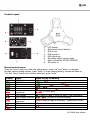
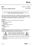
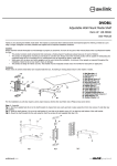
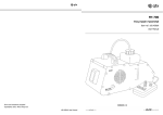
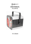
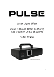
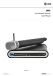
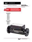
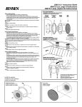
Item ref: 151.590UK TRI-SCAN Triple Head LED Scanner User Manual Please read through this manual thoroughly before use, any damage cause by misuse of product will not be covered by warranty. Thank you for choosing the QTX TRI-SCAN. This scanner boasts three heads, each with 5 high power LEDs in red, green, blue, white and amber. The three mirrors operate both independently and synchronised on the X axis providing large area coverage while giving a sharp and colourful moving effect. Operational in auto, sound-to-light or DMX modes, ideal for use as a centrepiece for a variety of small to medium sized venues, nightclubs or for mobile DJs. In the box: Your TRI-SCAN should arrive to you in good condition, supplied with mains leads and mounting bracket. If there is any damage or items missing contact your dealer immediately. Warning: To prevent risk of fire or electric shock, do not expose the unit to rain or damp environments. In the event of a spillage, disconnect the mains and allow the unit to dry out naturally. Qualified personnel should then check the unit before continuing use. Please do not open cover, contain high voltage. This product is not serviceable or repairable by end user. Please refer to qualified personnel for service and repair. Always check the correct voltage and the condition of the IEC lead before connecting to a power outlet. Always ensure any DMX leads used are in good condition with no short connections or damaged plugs. Setup: Installation should be carried out by qualified personnel only and must comply with HSG95 guidelines. This TRI-SCAN is suitable for overhead installation for floor scan or freestanding for er orinstallation professional when ceiling scan. For overhead it is advised to unit install malfunction. the unit 3 metres above the stage/ground, DO NOT face audience at head level. When installing overhead, always use a safety wire secured to the fixture by the safety hook behind the unit. Product Layout: 1. 2. 3. 4. 5. 6. 7. 8. LCD Display Back panel control buttons Built-in mic DMX signal in DMX signal out Secondary safety support hook Earth connection DO NOT REMOVE IEC power in Manual control menu: Press the “menu” button to enter the setting menu, press “up” and “down” to navigate through various setting options, press “enter” to enter desired setting, choose set value by “up” and “down” buttons and confirm setting by press “enter”. Display Operation: Mode DMX address DMX Channel mode Slave mode Auto mode Sound activation Microphone sensitivity LED display LED display inverted Fixture test sequence Fixture hours Software version Unit reset Press ENTER for setting to for 1 channel control or for 8 channel control = master, = slave 1,= slave 2 to = sound to light on, = sound to light off (0-100% gain) = stays on, = turns off after 10 sec untouched / (normal or inverted display) Fixture steps through all functions – press MENU to exit Displays how many hours of use for the fixture Press enter to reset to factory setting 151.590UK User Manual The TRI-SCAN can operate in stand-alone, master, slave or DMX modes. Stand-alone/master/slave – For stand-alone mode, first choose whether sound-to-light is required by selecting or from . Then select one of the 8 pre-programmed chase modes from option to , select for random chase option. Further TRI-SCAN units can be controlled by a master allowing synchronization. Ensure the control unit slave mode is set as and the controlled unit slave mode is set as or . Connect DMX out from the master unit to the DMX in of the slave unit for synchronized chase. allows slave unit to clone the master unit, allows slave unit to have independent movement from the master unit. DMX mode – Simply connect the DMX signal source to DMX in of the TRI-SCAN via a balanced XLR lead. Extra fixtures can be controlled by the same DMX signal from the loop through DMX signal on the DMX out. Ensure the correct DMX start address is set from the option on the manual control. Maintenance: There are no end-user serviceable parts within the unit. To maintain a workable condition we advice dusting the unit on a regular basis. Before cleaning or dusting, always ensure the mains power cable is removed from the unit. Use a soft cloth, lightly dampened with water or mild detergent to wipe off the dust from the casing. DO NOT use spray on the case as droplets may enter the unit through the ventilation and cause damage to electronics inside. Remove the trapped dust from the ventilation holes of the unit with a vacuum cleaner with a brush attachment, a dust blower or a hand brush. DMX channel value reference: 1 channel mode: Channel Channel 1 sound to light active from 008-255 DMX Value 000-007 008-037 038-067 068-097 098-127 128-157 158-187 188-217 218-247 248-255 Function Black out Pre-programmed Chase Pre-programmed Chase Pre-programmed Chase Pre-programmed Chase Pre-programmed Chase Pre-programmed Chase Pre-programmed Chase Pre-programmed Chase Random Chase 1-8 1 2 3 4 5 6 7 8 151.590UK User Manual 8 channel mode: Channel Channel 1 Channel 2 Channel 3 Channel 4 (Colour setting for scan head one) Channel 5 Channel 6 (Colour setting for scan head two) Channel 7 Channel 8 (Colour setting for scan head three) DMX Value 000-255 000-008 009-255 000-255 000-008 009-016 017-024 025-032 033-040 041-048 049-056 057-064 065-072 073-080 081-088 089-096 097-104 105-112 113-120 121-128 129-136 137-144 145-152 153-160 161-168 169-176 177-184 185-192 193-200 201-208 209-216 217-224 225-232 233-240 241-248 249-255 000-255 0-008 009-255 000-255 0-008 009-255 Function Master Dimmer, 0-100% No Strobe Strobe, speed increase with DMX value Scan head one, tilt position Black out R G B W A R+G R+B R+W R+A G+B G+W G+A B+W B+A W+A R+G+B R+G+W R+G+A R+B+W R+B+A R+W+A G+B+W G+B+A G+W+A B+W+A R+G+B+W R+G+W+A R+G+B+A R+B+W+A G+B+W+A R+G+B+W+A Scan head two, tilt position Black out Colour combination, please refer to Channel 4 value Scan head three, tilt position Black out Colour combination, please refer to Channel 4 value 151.590UK User Manual Specifications Power supply Power consumption (Max.) Fuse rating LED type LED colours DMX Chanels Dimensions Weight Laser & LED safety standard 110-240Vac, 50/60Hz (IEC) 60W T3A 15 x 3W 3 x red, 3 x green, 3 x blue, 3 x white, 3 x amber 1 or 8 390 x 390 x 150mm 3.6kg BSEN62471:2008 Troubleshooting No power (mains) No LED display No light output No strobe output Unresponsive to DMX Overheating/ cutting out Check mains voltage is correct and outlet is switched on Check IEC lead and fuse (if fuse continually blows, refer to your dealer) Press any control panel button and check LED setting in menu Check control panel mode settings (standby, slave, sensitivity, DMX) Check DMX settings from controller (dimmer levels, blackout etc.) Check strobe settings on control panel or from DMX controller Check DMX connection and leads Check that DMX mode is enabled (set “Addr” on control panel) Ensure that the unit is not too close to a heat source Ensure that adequate airflow is afforded for cooling This product is classed as Electrical or Electronic equipment and should not be disposed with other household or commercial waste at the end of its useful life. The goods must be disposed of according to your local council guidelines. Errors and omissions excepted. Copyright© 2014. AVSL Group Ltd. 151.590UK User Manual