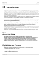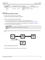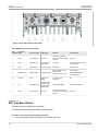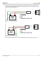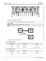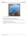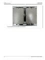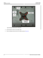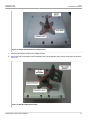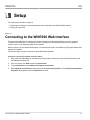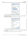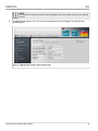
1
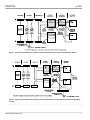
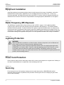
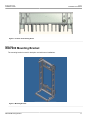
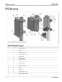
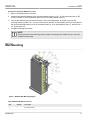
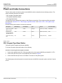
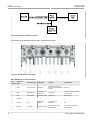
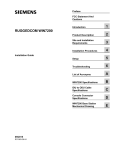
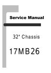
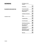
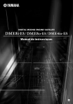
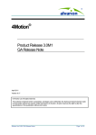
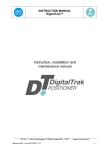
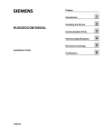
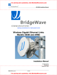
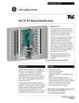
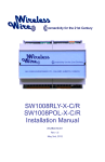
FCC Statement and
Cautions
RUGGEDCOM WIN7000
Installation Guide
9/2014
RC1062-EN-02
Introduction
1
Site and Installation
Requirements
2
Installation Procedures
3
Setup
4
Troubleshooting
5
Connector and Cable
Pinouts
A
WIN7000 Specifications
B
List of Acronyms
C
Warranty
D
RUGGEDCOM WIN7000
Installation Guide
ii
RUGGEDCOM WIN7000
Installation Guide
Table of Contents
Table of Contents
FCC Statement and Cautions .............................................................................
v
Chapter 1
Introduction ..........................................................................................................
1
1.1 About this Guide .......................................................................................................................... 1
1.2 Capabilities and Features ............................................................................................................. 1
1.3 Safety Information ........................................................................................................................ 2
1.3.1 General ............................................................................................................................. 2
1.3.2 Power Supply Requirements .............................................................................................. 2
1.3.3 Equipment Installation ........................................................................................................ 4
1.3.4 Radio Frequency (RF) Exposure ........................................................................................ 4
1.3.5 Lightning Protection ........................................................................................................... 4
1.3.6 Power Cord Protection ....................................................................................................... 4
1.3.7 Servicing ........................................................................................................................... 4
1.3.8 Antenna Grounding Requirements ...................................................................................... 5
1.3.9 Outdoor Grounding System ................................................................................................ 5
1.3.10 User Ports and Power Supply .......................................................................................... 5
1.3.11 Safety Hazards ................................................................................................................ 5
1.4 WIN7000 Physical Specifications .................................................................................................. 6
Chapter 2
Site and Installation Requirements .....................................................................
7
2.1 Mounting Considerations .............................................................................................................. 7
Chapter 3
Installation Procedures ........................................................................................
9
3.1 Pre-Installation Safety Instructions ................................................................................................ 9
3.2 Package Components and Unpacking ........................................................................................... 9
3.3 Installation Tools .......................................................................................................................... 9
3.4 Installing the Base Station .......................................................................................................... 10
3.4.1 Sealing Screw ................................................................................................................. 10
3.4.2 WIN7000 Mounting Bracket .............................................................................................. 11
3.4.3 Pole Mounting ................................................................................................................. 12
3.4.4 Wall Mounting ................................................................................................................. 13
3.4.5 Tower Mount ................................................................................................................... 14
iii
Table of Contents
RUGGEDCOM WIN7000
Installation Guide
3.4.6 Power and Cable Connections ......................................................................................... 15
3.4.6.1 PEC (Copper) Type Base Station .......................................................................... 15
3.4.6.2 SFA (Optical) Type Base Station ............................................................................ 17
3.4.6.3 SFD Type Base Station ......................................................................................... 18
3.4.7 Grounding the Device ...................................................................................................... 21
3.4.8 Installing the GPS Antenna .............................................................................................. 21
3.4.9 2.3GHz Band Cavity Filters Installation ............................................................................. 22
3.5 Weatherproofing ......................................................................................................................... 30
3.5.1 Weatherproofing Cable Connections ................................................................................. 31
3.6 Hazardous Location Information .................................................................................................. 34
3.7 Hazardous Location Installation ................................................................................................... 34
Chapter 4
Setup ..................................................................................................................
37
4.1 Connecting to the WIN7000 Web Interface .................................................................................. 37
Chapter 5
Troubleshooting ..................................................................................................
41
5.1 No IP connectivity ...................................................................................................................... 41
5.2 No Serial Connection ................................................................................................................. 41
Appendix A
Connector and Cable Pinouts ............................................................................
43
A.1 Power and Ethernet Cable Pinouts ............................................................................................. 43
A.2 Console Cable Pinouts ............................................................................................................... 44
Appendix B
WIN7000 Specifications .....................................................................................
45
Appendix C
List of Acronyms ................................................................................................
47
Appendix D
Warranty .............................................................................................................
iv
49
RUGGEDCOM WIN7000
Installation Guide
FCC Statement and Cautions
FCC Statement and Cautions
Federal Communications Commission Radio Frequency Interference Statement
This equipment has been tested and found to comply with the limits for a Class A digital device pursuant to Part
15 of the FCC Rules. These limits are designed to provide reasonable protection against harmful interference
when the equipment is operated in a commercial environment. This equipment generates, uses and can radiate
radio frequency energy and, if not installed and used in accordance with the instruction manual, may cause
harmful interference to radio communications. Operation of this equipment in a residential area is likely to cause
harmful interference in which case the user will be required to correct the interference at his own expense.
CAUTION!
Caution: Service
This product contains no user-serviceable parts. Attempted service by unauthorized personnel shall
render all warranties null and void.
Changes or modifications not expressly approved by RUGGEDCOM could invalidate specifications,
test results, and agency approvals, and void the user’s authority to operate the equipment.
CAUTION!
Caution: Physical Access
This product should be installed in a restricted access location where access can only be gained by
service personnel or users who have been instructed about the reasons for the restrictions applied to
the location and about any precautions that shall be taken; and access is through the use of a tool or
lock and key, or other means of security, and is controlled by the authority responsible for the location.
v
RUGGEDCOM WIN7000
Installation Guide
FCC Statement and Cautions
vi
RUGGEDCOM WIN7000
Installation Guide
Chapter 1
Introduction
Introduction
The WIN7000 High Power Base Station is a member of the RUGGEDCOM WIN family, a line of mobile WiMAX
broadband wireless access systems based on the 802.16e mobile WiMAX standard. RUGGEDCOM systems are
designed for robustness and simplicity, offering feature-rich services with low deployment and operation costs.
The WIN7000 is a member of a line of mobile WiMAX broadband wireless access systems based on the 802.16e
mobile WiMAX standard. These systems are designed for robustness and simplicity, offering feature-rich services
with low deployment and operation costs.
The WIN7000 is a cost-effective solution for wireless access services, designed for point-to-multipoint broadband
wireless access applications in varying conditions and locations. It is a one-sector base station.
The base station communicates with fixed and mobile subscriber units, according to defined service criteria and
customer service level agreements. The WIN7000 also connects to the service provider backbone, supporting
end-to-end Quality of Service (QoS) requirements.
The system uses OFDMA radio technology, providing robustness in adverse channel conditions and enabling
Non-Line-Of-Sight (NLOS) operation. This improves coverage and maintains a high level of spectral efficiency.
Modulation and coding are continuously adapted to prevailing link conditions, ensuring an optimal balance
between robustness and efficiency. The use of STC/MRC and MIMO radio technologies optimizes link
performance, ensuring enhanced bandwidth and service coverage.
The RUGGEDCOM WIN7000 is a full outdoor base station, designed for easy installation and mounting on poles,
street lamps, towers, or walls. The WIN7000 can be equipped with copper or fibre network interfaces for flexible
integration into the operator’s backbone.
The WIN7000 is supported by RUGGEDCOM NMS, Siemens’s comprehensive Network Management System.
Section 1.1
About this Guide
This installation guides describes the installation of the WIN7000 High Power Base Station.
This guide is intended for use by base station installers and operators, and assumes readers have a working
knowledge of WiMAX technologies and procedures. While some safety precautions are reviewed here, it
is assumed that installers are trained in safe installation practices. Users unfamiliar with safe installation
procedures, WiMAX technologies, and service procedures should not rely on this manual for comprehensive
guidance.
Section 1.2
Capabilities and Features
The WIN7000 provides the full base station functionality necessary for serving a single sector:
• Supported Frequency Bands: 5251, 5151, 7251
• All-outdoor, single-box installation
• IEEE802.16e Wave2 Standard Compliance
About this Guide
1
Chapter 1
Introduction
RUGGEDCOM WIN7000
Installation Guide
• Backbone Ethernet connectivity via a 10/100 Base-T network interface
• Fixed and mobile CPE support
• 3.5 MHz, 5MHz, 7MHz and 10MHz channel bandwidth support
• MIMO (2×2) support
• Various Radio Frequency (RF) options, including 1.x, 2.x and 3.x GHz band support
• Traffic classification and connection establishment initiation
• Quality of Service (QoS) management
• Alarm management
• Internal SNMP agent, enabling extensive In-Band (IB) management of the base station and its registered CPEs
• R6 interface to ASN-GW profile C
• Power requirement: 48VDC
Section 1.3
Safety Information
Section 1.3.1
General
• Read this user manual and follow all operating and safety instructions.
• The base station and antenna must be installed by a professional installer.
• Do not exceed the described limits.
Section 1.3.2
Power Supply Requirements
• The power supply unit should be a Class 2 power supply, safety-certified according to national codes.
• Maximum output current should not exceed 5A.
• Maximum output voltage of the power supply should not exceed 60VDC.
• Minimum output voltage should not be below 42VDC.
• The disconnecting device is defined as the following:
▪ When connected to an AC/DC power supply, the appliance coupler of the AC/DC power supply is regarded
as the main disconnecting device for the base station.
▪ When connected to a DC battery power supply, a double pole circuit breaker, rated 10A 60VDC, is regarded
as the main disconnecting device for the base station.
The unit is considered to be connected to a centralized DC power system, therefore the power line should be
grounded. The unit should be permanently connected to ground with 16AWG cable or less. See the figures below
for two methods of power grounding (from the UL 60950-1 standard; according to UL 60950-22). When the unit is
connected to a centralized DC Power System, the "+" side of the supply should be grounded, as per UL60950-1
and UL 60950-22 requirements.
2
Safety Information
RUGGEDCOM WIN7000
Installation Guide
Chapter 1
Introduction
Figure 1: Typical Centralized DC Power System, Plant and Distribution Source-Grounded DC Power System
Figure 2: Typical Centralized DC Power System, Plant and Distribution DC Power System Grounded at Equipment
Location
Power Supply Requirements
3
Chapter 1
RUGGEDCOM WIN7000
Introduction
Installation Guide
Section 1.3.3
Equipment Installation
Install the equipment in accordance with the electrical code relevant to the country of installation, such as the
National Electrical Code (NEC), ANSI/NFPA 70; the Canadian Electrical Code (CEC), Part 1, CSA C22.1;
and when applicable, the National Electrical Safety Code IEEE C2. Unless marked or otherwise identified, the
Standard for the Protection of Electronic Computer/Data Processing Equipment, ANSI/NFPA 75, also applies.
Section 1.3.4
Radio Frequency (RF) Exposure
The WIN7000 is compliant with the requirements set forth in CFR 47, section 1.1307, addressing Radio
Frequency (RF) exposure from radio frequency devices as defined in OET Bulletin 65. The emitted radiation
should be as little as possible. To achieve minimum RF exposure, install the WIN7000 when it is configured not
to transmit and set it to operational mode remotely, rather than enabling transmission by the installer on-site. For
maintenance of the WIN7000, or other operations which require RF exposure, the exposure should be minimized
in time and according to the regulations set by the FCC or the regulations relevant to the country of installation.
Section 1.3.5
Lightning Protection
WARNING!
When the WIN7000 is installed in an outdoor location, all indoor components (such as Ethernet and
power supply) should be connected through a lightning protector.
Lightning protection protects people and equipment located indoors from lightning that might strike
the WIN7000 or its outdoor cables. Therefore, install the lightning protector device indoors, as close
as possible to the point where the cables enter the building. The lightning protector can also be
installed outdoors as long as the cables that lead indoors are well protected from lightning between the
protector and the building entrance.
Section 1.3.6
Power Cord Protection
Route all power supply cords so that people cannot walk on them or place objects on or against them. Walking on
the cords or placing objects on or against the cords can damage the cords.
Section 1.3.7
Servicing
Do not open the cover of this product to attempt service unless instructed by a RUGGEDCOM certified
technician. Refer all repairs to qualified service personnel. Removing the covers or modifying any part of this
device voids its warranty.
4
Equipment Installation
RUGGEDCOM WIN7000
Installation Guide
Chapter 1
Introduction
Siemens does not endorse or support the use of proprietary third-party outdoor cable assemblies not supplied by
Siemens.
WARNING!
Keep away from electric power lines.
You can be killed if the antennas are in close proximity to electric power lines. Carefully read and
follow all instructions in this manual. By nature of the installation, you may be exposed to hazardous
environments and high voltage. Use caution when installing the outdoor system.
Section 1.3.8
Antenna Grounding Requirements
The antenna installation must be as per Article 810 of the NEC. Of particular note is the requirement that the
grounding conductor not be less than 10 AWG (Cu). The scheme should be either in accordance with UL 96 and
96A Lightning Protection Components and Installation Requirements for Lightning Protection Systems, or tested
in accordance with UL 50 and UL 497.
Section 1.3.9
Outdoor Grounding System
WARNING!
Verify that the base station is grounded.
The system must be properly grounded to protect against power surges and accumulated static
electricity. It is the installer’s responsibility to install this device in accordance with the local electrical
codes.
Section 1.3.10
User Ports and Power Supply
If the length of outdoor exposed communication lines is greater than 40 m (140 feet), these lines must be treated
as TNV-1 circuits. The installer must ensure that the power supply and network ports are designed for full
compliance with the TNV-1 telecommunication network.
Section 1.3.11
Safety Hazards
WARNING!
Installing the WIN7000 can pose a serious hazard. Be sure to take precautions to avoid the following:
• Exposure to high voltage lines during installation
• Falling when working at heights or with ladders
• Injuries from dropping tools
Antenna Grounding Requirements
5
Chapter 1
RUGGEDCOM WIN7000
Introduction
Installation Guide
• Contact with AC wiring (power system connection)
WARNING!
To reduce the risk of fire, use only 26AWG or larger telecommunication line cord.
Section 1.4
WIN7000 Physical Specifications
The WIN7000 is packed in a waterproof metal housing. A mounting bracket and mounting kit allows for pole or
wall installation. The assembled unit weighs approximately 15kg.
For information on the WIN7000 wiring connections, see Section 3.4.6, “Power and Cable Connections”.
Figure 3: WIN7000 Dimensions
6
WIN7000 Physical Specifications
RUGGEDCOM WIN7000
Installation Guide
Chapter 2
Site and Installation Requirements
Site and Installation
Requirements
Section 2.1
Mounting Considerations
When choosing a mounting location, consider the available mounting structures and antenna clearance. To
provide better weather protection, the WIN7000 should be mounted with the connection panel facing downwards.
The base station is equipped with a mounting kit, which allows several mounting options:
• Poles: Attach the WIN7000 to any pipe or pole with diameter 1.75" to 10".
• Towers and Walls: Attach the WIN7000 to any tower or wall that can support the load of the unit.
The following antenna options are available:
• 2 × omni-directional antenna
• External sector dual slant ±45º antenna
• Two separate antennas
Before mounting the antennas, conduct a site survey to determine the optimal position for the antennas. Observe
the following guidelines:
• Mount the antennas at the highest point possible. Reception will increase according to the height of the
antennas.
• Mount the antennas in a place with as few obstacles as possible between the antennas and the planned
service area.
• To avoid interference, mount the antennas and base station as far as possible from antennas of other devices
and other base stations.
• To keep the cable from the base station to the antenna as short as possible, mount the antennas as close
as possible to the base station. Using a cable longer than 2 meters will result in greater loss and more
interference, as the cable will act as an antenna.
• Do not point the antennas directly at populated areas, and locate the antennas at least 3.6 m from people and
public areas.
• Mount the antennas and base station in a place that allow for maintenance access to the unit.
• Mount the GPS antenna in a position where the whole sky is visible to the antenna. If the base station is
mounted on a wall and the GPS antenna is mounted on top of the base station, only half of the sky will be
visible to the antenna. This may not be enough for proper operation.
Mounting Considerations
7
RUGGEDCOM WIN7000
Installation Guide
Mounting Considerations
Chapter 2
Site and Installation Requirements
8
RUGGEDCOM WIN7000
Installation Guide
Chapter 3
Installation Procedures
Installation Procedures
Section 3.1
Pre-Installation Safety Instructions
WARNING!
Installing the WIN7000 can pose a serious hazard. Be sure to take precautions to avoid the following:
• Exposure to high voltage lines during installation
• Falling when working at heights or with ladders
• Injuries from dropping tools
• Contact with AC wiring (power system connection)
Section 3.2
Package Components and Unpacking
Check that the package contains:
• WIN7000.
• GPS antenna
• 2 × RF cables 1.6 m for connection to antenna
• Pole / wall mount kit
• WINPS 48V power supply for Copper and SFA configuration
Section 3.3
Installation Tools
• Phillips screwdriver
• Wrench or socket set
• Drill and 5/16" drill bit
• Self-fusing electrical tape or insulating putty suitable for use in the unit’s installation environment
Pre-Installation Safety Instructions
9
Chapter 3
RUGGEDCOM WIN7000
Installation Procedures
Installation Guide
Section 3.4
Installing the Base Station
WARNING!
The equipment should be installed in compliance with the National Electrical Code (NEC), ANSI/
NFPA 70, the Canadian Electrical Code (CEC), Part 1, CSA C22.1; and when applicable, the National
Electrical Safety Code IEEE C2. Unless marked or otherwise identified, the Standard for the Protection
of Electronic Computer/Data Processing Equipment, ANSI/NFPA 75.
The following components are required for the installation:
• Mounting bracket
• WIN7000
• RF antennas
• GPS antenna
• Power supply
• Ground, data, and power cables
To install the WIN7000, follow these general steps:
1. Install the mounting bracket at the chosen location.
2. Install the antennas.
3. Prepare the grounding cables.
4. Lay out the connection cables.
5. Mount the power supply.
6. Mount the base station to the mounting bracket.
7. Connect all cables to the WIN7000 and seal connections with suitable electrical tape or putty.
Section 3.4.1
Sealing Screw
CAUTION!
Do not attempt to open the sealing screw on the bottom side of base-station. Opening the screw will
break the sealing and will cause the moisture getting into the base-station.
10
Installing the Base Station
RUGGEDCOM WIN7000
Installation Guide
Chapter 3
Installation Procedures
Figure 4: Location of the Sealing Screw
Section 3.4.2
WIN7000 Mounting Bracket
The mounting bracket is used for both pole- and wall-mount installations.
Figure 5: Mounting Bracket
WIN7000 Mounting Bracket
11
Chapter 3
RUGGEDCOM WIN7000
Installation Procedures
Installation Guide
Section 3.4.3
Pole Mounting
Figure 6: WIN7000 Pole Mounting Diagram
Table: WIN7000 Pole Mount Parts List
12
Item
Quantity
Description
1
1
Mounting brackets
2
1
WIN7000
3
2
Fastening brackets
4
4
Screw 5/16" hex cap × 6"
5
8
Nut NF 16 hex
6
10
Washer flat 5/16"
7
10
Washer spring 5/16"
8
4
Screw NC 1/4" × 1/2" hex
9
4
Washer flat NC 1/4"
10
4
Washer spring NC 1/4
11
1
Pole
12
2
Bolt NC 1/4"
13
2
Screw NC 5/16" × 1/2"
14
1
Mounting Upper Bracket
Pole Mounting
RUGGEDCOM WIN7000
Chapter 3
Installation Guide
Installation Procedures
Procedure: Installing the WIN7000 on a Pole
1.
Select a mounting location on the pole.
2.
Assemble the fastening brackets to the mounting bracket using the 5/16" × 6" hex cap screws (Item 4), NF
16 hex nuts (Item 5), 5/16" flat washers (Item 6), and 5/16" spring washers (Item 7).
3.
Lift the base station by the eye bolts and secure it to the mounting bracket. At the top of the unit and
mounting bracket, use NC 1/4" × 1/2" hex screws (Item 8) and NC 1/4" flat washers (Item 9). At the bottom of
the unit and mounting bracket, use 5/16" flat washers (Item 6), 5/16" spring washers (Item 7), and NC 5/16" ×
1/2" screws (Item 13).
4.
Complete the wiring connections.
NOTE
Seal all connectors with self-fusing electrical tape or insulating putty suitable for use in the unit’s
installation environment
Section 3.4.4
Wall Mounting
Figure 7: WIN7000 Wall Mounting Diagram
Table: WIN7000 Wall Mount Parts List
Item
Quantity
Description
1
1
Mounting brackets
Wall Mounting
13
Chapter 3
RUGGEDCOM WIN7000
Installation Procedures
Installation Guide
Item
Quantity
Description
2
1
WIN7000
3
4
Screw NC 1/4" × 1/2" hex
4
4
Washer flat NC 1/4"
5
4
Washer spring NC 1/4"
6
2
Bolt NC 1/4"
7
4
Screw 5/16" hex cap × 2"
8
4
Washer flat 5/16"
9
4
Washer spring 5/16"
10
4
Dowel 5/16"
11
1
Mounting upper bracket
Procedure: Installing the WIN7000 on a Wall
1.
Select a mounting location.
2.
Place the mounting bracket on the wall and mark the location of the four mounting holes, two at the top and
two at the bottom.
3.
With a 5/16" drill bit suitable for the wall material, drill holes at the marked locations.
4.
Insert the 5/16" dowels (Item 10) into the holes.
5.
Assemble four 5/16" flat washers (Item 8), four 5/16" spring washers (Item 9), and four 5/16" × 2" hex cap
screws (Item 7) into the holes on the mounting bracket.
6.
Secure the mounting bracket to the wall.
7.
Lift the base station by the eye bolts and secure it to the mounting bracket. At the top of the unit and
mounting bracket, use NC 1/4" × 1/2" hex screws (Item 3), NC 14" flat washers (Item 4), and NC 1/4" spring
washers (Item 5).
8.
Complete the wiring connections.
NOTE
Seal all connectors with self-fusing electrical tape or insulating putty suitable for use in the unit’s
installation environment. For more information on sealing the connectors, see Section 3.5,
“Weatherproofing”.
Section 3.4.5
Tower Mount
Follow the same procedure as for wall mounting; see Section 3.4.4, “Wall Mounting”. Ensure that the tower can
hold the load of the base station.
14
Tower Mount
RUGGEDCOM WIN7000
Chapter 3
Installation Guide
Installation Procedures
Section 3.4.6
Power and Cable Connections
There are three power connection options for the WIN7000, which are described in the following sections. The
power connection options are as follows:
• PEC (Copper) Type Base Station
• SFA (Optical) Type Base Station
• SFD Type Base Station
The WIN7000 can be equipped with copper or fiber Ethernet connections. These copper and fiber port options
are described in Section 3.4.6.1, “PEC (Copper) Type Base Station” and Section 3.4.6.2, “SFA (Optical) Type
Base Station”.
Use the following tools to fasten or loosen the connectors:
Description
Manufacturer
Tool Number
Type
Torque
Connector Name
Type-N 1 Nm Variant
Wrench, 20 mm
Tessco
13055
Hexagon
1.35 N·m (11.9 lbf-in)
ANT1/ANT2
Modular Plugs
Connector Removal
Tool, BNC/TNC, 12"
Ideal
35-042
Round
0.56 N·m (4.9 lbf-in)
GPS
Curved Jaw Locking
Plier
Irvin
502L3
Curved
4 N·m (35.4 lbf-in)
DC/ETH
Section 3.4.6.1
PEC (Copper) Type Base Station
The power system is supplied by Siemens (WINPS).
To connect the power system and cables, do the following:
Procedure: Connecting the Power System and Cables
1.
Connect the supplied combo (DC + Ethernet cable) to the power system (WINPS) port labeled DC + ETH.
2.
Connect the other end to port 6 on the WIN7000 unit as shown in Figure 9.
3.
Connect the Ethernet input to the 10/100 Base-T connector on the power system.
The following figure shows the physical connection between the WIN7000, the power system, and the AC power
source.
Power and Cable Connections
15
Chapter 3
RUGGEDCOM WIN7000
Installation Procedures
Installation Guide
Figure 8: Base Station Power Connection
The following figure and table show the ports, connectors and cables.
Figure 9: Copper Ethernet Port Option
Table: WIN7000 Connectors and Cables
16
Port
Connector
Number Name
Connector Type
Cable Type
Function
Connected to
1
ANT1
N type Female
RG 6 or 9
Connected to external
antenna or omni-directional
antenna
Antenna
2
GND
Adjustable nut
#10 AWG bare
copper wire
Grounding
Central earth ground, tower
or pole chassis
3
GPS
TNC Female
Proprietary cable
GPS signal
GPS antenna
4
Not used
5
Console
3-pin
UART 3P to
DB9F"
Low level CLI for
technicians
PC
6
DC/ETH
DC + ETH
Proprietary cable
48 VDC/ Return / 5A +
Ethernet Cat5
Power supply + Network/
Router/Switch
PEC (Copper) Type Base Station
RUGGEDCOM WIN7000
Chapter 3
Installation Guide
Installation Procedures
Port
Connector
Number Name
Connector Type
Cable Type
Function
Connected to
7
N type Female
RG 6 or 9
Connected to external
antenna or omni-directional
antenna
Antenna
ANT2
Section 3.4.6.2
SFA (Optical) Type Base Station
The power system is supplied by Siemens (WINPS).
To connect the power system and cables, do the following:
Procedure: Connecting the Power System and Cables
1.
Connect the supplied DC cable to the power system (WINPS) port labeled DC+ETH.
2.
Connect the other end of the cable to the DC/ETH port on the WIN7000 shown as port 4 in Figure 11.
3.
Connect the optical cable to the F/O connector on the WIN7000 (for more information, see Figure 11).
4.
Connect the optical cable to the network switch.
NOTE
The fiber optic standard is Gigabit Ethernet 1000 Base-LX.
The following figure shows the physical connection between the WIN7000, the power system, and the AC power
source.
Figure 10: Base Station Power Connection
The following figure and table show the ports, connectors and cables.
SFA (Optical) Type Base Station
17
Chapter 3
RUGGEDCOM WIN7000
Installation Procedures
Installation Guide
Figure 11: Fiber Optic Ethernet Port Option
Table: WIN7000 Connectors and Cables
Port
Connector
Number Name
Connector Type
Cable Type
Function
Connected to
1
ANT1
N type Female
RG 6 or 9
Connected to external
antenna or omni-directional
antenna
Antenna
2
GND
Adjustable nut
#10 AWG bare
copper wire
Grounding
Central earth ground, tower
or pole chassis
3
GPS
TNC Female
Proprietary cable
GPS signal
GPS antenna
DC/ETH or DC
DC/ETH or DC
Proprietary cable
48 VDC / Return / 5A +
Ethernet Cat5
Power supply +
4
Or 48 VDC / Return / 5A
Or Power supply
5
Console
Network/Router/Switch
3-pin
UART 3P to
DB9F"
Low level CLI for
technicians
PC
Optic 100M/1GMbit
Network/Router/Switch
Connected to external
antenna or omni-directional
antenna
Antenna
6
F/O
Optic SM Mini LC
Fiber Optic SM
OFNR I/O with
Industrial Plug,
ODVA Cable
7
ANT2
N type Female
RG 6 or 9
Section 3.4.6.3
SFD Type Base Station
The power system is supplied by the operator.
To connect the power system and cables, do the following:
Procedure: Connecting the Power System and Cables
1.
18
Connect the power system DC output to the supplied connector.
SFD Type Base Station
RUGGEDCOM WIN7000
Installation Guide
2.
Chapter 3
Installation Procedures
Connect the other end (open end) of the supplied cable to the operator’s power system (according to the
labelling on the cable and the following tables). For more information, see Figure 12 and Figure 13, which
show +48V and -48V configurations.
Figure 12: Positive 48V Configuration
Figure 13: Negative 48V Configuration
3.
Connect the optical cable to the F/O connector on the WIN7000 (for more information, see Figure 14).
SFD Type Base Station
19
Chapter 3
RUGGEDCOM WIN7000
Installation Procedures
Installation Guide
Figure 14: Fiber Optic Ethernet Port Option
4.
Connect the optical cable to the network switch (for more information, see Figure 15).
NOTE
The fiber optic standard is Gigabit Ethernet 1000 Base-LX.
Figure 15: Base Station Power Connection
Table: +48 VDC Power System
Supplied Cable
Power Supply
Note
-48VDC
-48VDC
GND
+48VDC
+48VDC/ GND
“HOT Line”
GND
-48VDC/ GND
Connect -48V and GND
Supplied Cable
Power Supply
Note
-48VDC
-48VDC
“HOT Line”
+48VDC
+48VDC/ GND
GND
Table: -48 VDC Power System
20
SFD Type Base Station
RUGGEDCOM WIN7000
Chapter 3
Installation Guide
Installation Procedures
Supplied Cable
Power Supply
Note
GND
+48VDC/ GND
Connect +48V and GND
Section 3.4.7
Grounding the Device
To ground the device, do the following:
Procedure: Grounding the Device
1.
Assemble the ground connection as shown:
1
2
3
4
3
2
5
6
Figure 16: Ground Cable Assembly
1. Ground Stud
2.
2. Flatwasher
3. External Tooth Lockwasher
4. 10 AWG Isolated Ring
5. Nut
6. 10 AWG Ground Wire
Using a 1/4" square drive socket, torque the nut to 8.5 N·m (75 lbf-in).
Section 3.4.8
Installing the GPS Antenna
To install the GPS antenna, do the following:
Procedure: Installing the GPS Antenna
1.
Mount the GPS antenna as shown in Figure 17.
Grounding the Device
21
Chapter 3
RUGGEDCOM WIN7000
Installation Procedures
Installation Guide
Figure 17: Installing the GPS Antenna
2.
Connect the GPS cable (TNC female connector) between the antenna and the base station.
Section 3.4.9
2.3GHz Band Cavity Filters Installation
To comply with FCC limits, the unit must be connected to cavity filters (for full-power configuration only).
Follow these steps to assemble the 2.3GHz cavity filters and connect them to the base station antennas.
There are two types of cavity filters: one for A+B band, and one for C+D band.
Figure 18: A+B Band Cavity Filter
22
2.3GHz Band Cavity Filters Installation
RUGGEDCOM WIN7000
Installation Guide
Chapter 3
Installation Procedures
Figure 19: C+D Band Cavity Filter
The cavity filter mounting kit provides the following mounting options:
• Pole mounting: Attach the filters to any pipe or pole with a diameter of 1.75" to 10".
• Wall mounting: Attach the filters to any wall that can support the weight of the filters and mounting bracket.
Procedure: Assembling and Connecting Cavity Filters
1.
Position the cavity filters (Item 1 × 2) on the baseplate (Item 2).
2.
Secure the filters to the baseplate using Flat Washer (M5), Spring Washer (M5), and Screw (M5) (Items 3, 4,
and 5 × 8).
2.3GHz Band Cavity Filters Installation
23
Chapter 3
Installation Procedures
RUGGEDCOM WIN7000
Installation Guide
Figure 20: A+B Band Cavity Filters Mounted on Baseplate
24
2.3GHz Band Cavity Filters Installation
RUGGEDCOM WIN7000
Installation Guide
Chapter 3
Installation Procedures
Figure 21: C+D Band Cavity Filters Mounted on Baseplate
3.
Position the adaptor plate (MT-120018) on the baseplate in the position shown in Figure 22.
4.
Secure the adaptor plate using Flat Washer (M5), Spring Washer (M5), and Hex Nut (M5) (Items 2, 3, and 4
× 4).
2.3GHz Band Cavity Filters Installation
25
Chapter 3
Installation Procedures
RUGGEDCOM WIN7000
Installation Guide
Figure 22: Adaptor Plate Mounted on Baseplate
26
5.
Insert the adaptor bracket into the adaptor plate.
6.
Secure the adaptor bracket with Set Screw (M5) as shown in Figure 23.
2.3GHz Band Cavity Filters Installation
RUGGEDCOM WIN7000
Installation Guide
Chapter 3
Installation Procedures
Figure 23: Adaptor Bracket Mounted to Adaptor Plate
7.
Attach the wall mount bracket to the adaptor bracket.
8.
Secure the wall mount bracket with Flat Washer (M5), Spring Washer (M5), and Set Screw (M5) as shown in
Figure 24.
Figure 24: Wall Mount Bracket Assembly
2.3GHz Band Cavity Filters Installation
27
Chapter 3
Installation Procedures
RUGGEDCOM WIN7000
Installation Guide
NOTE
For the wall mounting option, assembly of the cavity filter mounting bracket is now complete.
Mount the assembly to the wall and complete the antenna connections described in Step 11.
9.
For pole mounting, attach the pole mounting bracket to the wall mounting bracket as shown in Figure 25.
10. Secure the pole mounting bracket with Flat Washer (M5), Spring Washer (M5), and Set Screw (M5) as
shown in Figure 25.
Figure 25: Pole Mount Bracket Assembly
11. Connect the RF cables to the cavity filters and the base station. Connect cavity filter IN to the base station.
Connect cavity filter OUT to the antenna.
28
2.3GHz Band Cavity Filters Installation
RUGGEDCOM WIN7000
Installation Guide
Chapter 3
Installation Procedures
Figure 26: A+B Band Cavity Filter Antenna Connections
2.3GHz Band Cavity Filters Installation
29
Chapter 3
Installation Procedures
RUGGEDCOM WIN7000
Installation Guide
Figure 27: C+D Band Cavity Filter Antenna Connections
Section 3.5
Weatherproofing
It is extremely important to weatherproof all outdoor cable connections. Weatherproofing the connections at the
outdoor unit and antennas prevents corrosion, prevents water from interfering with the connection, and helps to
keep the connection tight. Because cables also carry DC current, the need for proper weatherproofing cannot be
overstated.
We recommend the use of sealing tapes designed for outdoor use:
• 3M™ Scotch® Super 88 Electrical Tape
• Heavy-duty weather-, abrasion-, and UV-resistant rubber splicing tape or self-amalgamating tape
Rubber mastic putty or duct sealing putty must also be used to complete the weatherproofing where needed.
We do not recommend silicon seal or glue. These materials are difficult to apply accurately and are difficult to
remove. Do not use PVC tape.
30
Weatherproofing
RUGGEDCOM WIN7000
Installation Guide
Chapter 3
Installation Procedures
Section 3.5.1
Weatherproofing Cable Connections
Most outdoor unit, antenna, or cable problems are caused by coaxial cable connections loosened by vibration,
allowing moisture to penetrate the connector interface. We recommend that all outdoor unit-to-cable connections
be weatherproofed using a procedure similar to the one described below.
This method of weatherproofing must be completed on all external connections. If surge arrestors are used, all
the associated connections and arrestors must be completely wrapped with splicing tape or self-amalgamating
tape.
NOTE
Before waterproofing, ensure all connectors are correctly tightened. Ensure the connector and cables
are free of foreign substances such as oil, water, grease, and dirt. Ensure that the cable extends below
the connector to which it is attached, providing a path for water to follow away from the connected
device.
Procedure: Weatherproofing Cable Connectors
1.
Begin to wrap the rubber-splicing or self-amalgamating tape. Start as close to the equipment body as
possible. Stretch and wind the tape around the connector housing, ensuring there are no gaps in the tape.
Figure 28: Wrapping the Connector with Rubber-splicing or Self-amalgamating Tape
2.
Tightly wrap the connector and the cable. Overlap the tape, without gaps, all the way along the connector.
Continue wrapping the tape 25 mm (1") onto the cable.
Weatherproofing Cable Connections
31
Chapter 3
RUGGEDCOM WIN7000
Installation Procedures
Installation Guide
Figure 29: Wrapping the Cable with Rubber-splicing or Self-amalgamating Tape
3.
For UV protection of the rubber splicing tape, wrap two layers of electrical tape on top of the rubber splicing
tape.
Figure 30: Wrapping the Connector with Electrical Tape
4.
32
Work mastic putty or duct sealing putty between the connector and the body of the radio or antenna. Ensure
the putty fills any gaps not covered by the tape.
Weatherproofing Cable Connections
RUGGEDCOM WIN7000
Installation Guide
Chapter 3
Installation Procedures
Figure 31: Sealing Gaps with Putty
5.
Apply two layers of electrical tape over the rubber splicing tape for UV protection.
Figure 32 and Figure 33 show the base station connectors wrapped with splicing and electrical tape, before the
application of mastic or duct sealing putty.
Figure 32: Wrapped Connectors before the application of Weathproofing Putty
Weatherproofing Cable Connections
33
Chapter 3
Installation Procedures
RUGGEDCOM WIN7000
Installation Guide
Figure 33: Detail of Wrapped Connectors
WARNING!
Assembly without waterproof sealing tape or removing the waterproof sealing tape from this device
voids its warranty.
Section 3.6
Hazardous Location Information
The following is the hazardous location information for this equipment:
nA IIC T4 GC X II 3G
Rating: 48VDC,4A
Class I Division 2 Groups A,B,C,D
T4
Section 3.7
Hazardous Location Installation
Hazardous Location Considerations
This equipment is suitable for use in Class 1, Division 2, Groups A, B, C, D or non-hazardous locations only. The
following ATTENTION statement applies to use in hazardous locations.
WARNING!
EXPLOSION HAZARD
• Substitution of components may impair suitability for Class I, Division 2
• Do not disconnect equipment unless power has been switched off or the area is known to be nonhazardous.
34
Hazardous Location Information
RUGGEDCOM WIN7000
Chapter 3
Installation Guide
Installation Procedures
Environnements Dangereux
Cet équipement est conçu pour être utilisé dans des environnements de Classe 1 ,Division 2, Groupes A, B, C, D
ou non dangereux. La mise en garde suivante s’applique à une utilisation dans des environnements dangereux.
WARNING!
RISQUE D’EXPLOSION
• La substitution decomposants peut rendre ce matériel inacceptable pour les emplacements de
Classe I, Division 2.
• Avant de déconnecter l’equipment, couper le courant ou s’assurer que l’emplacement est désigné
non dangereux.
This equipment is suitable for use in Class 1, Division 2, Groups A, B, C, D hazardous locations when installed
using the Class 1, Division 2 installation kit (P/N MKIT0109).
Contents of the Class 1, Division 2 Installation Kit:
• WIN1212 Surge Suppression Unit
• DC cable for connection between the power supply unit (PSU) and the WIN1212 unit
To install the equipment in a hazardous location, do the following:
1.
Connect a DC cable between the PSU and WIN1212 unit.
WIN1212
Figure 34: Complete Class 1 Division 2 Installation Kit
2.
Connect a Category 5e cable between the WIN1212's Data and Power Output connections and the base
station. For more information, refer to the RUGGEDCOM WIN1210/1212 Installation Guide.
3.
Connect a Category 5e cable between the Ethernet switch and the WIN1212's Data Input port.
Hazardous Location Installation
35
Chapter 3
Installation Procedures
4.
RUGGEDCOM WIN7000
Installation Guide
Connect the AC open-ended cable to the PSU.
CAUTION!
The power supply AC cord should be 3 wires, 18 AWG minimum, with a length of less than 4.5 m, and
safety certified according to national rules.
36
Hazardous Location Installation
RUGGEDCOM WIN7000
Installation Guide
Chapter 4
Setup
Setup
The initial setup procedure consists of:
• Configuring the computer’s network parameters and connecting to the WIN7000 Web interface
• Verifying IP connectivity
Section 4.1
Connecting to the WIN7000 Web Interface
This section describes how to configure the network parameters in Microsoft Windows so you can connect a
computer to the WIN7000. For instructions on how to configure the network parameters for other operating
systems, refer to your operating system documentation.
Before beginning, ensure that the base station is connected to the Power over Ethernet (PoE) power adaptor and
that power is applied.
Follow these steps connect a computer to the WIN7000 Web interface:
Procedure: Connecting a computer to the base station
1.
Ensure that the PoE adaptor is connected to the base station. Connect the computer’s Ethernet port to the
PoE adaptor’s Ethernet port.
2.
On the computer, click Start and select Control Panel.
3.
In the Control Panel, select Network and Internet Connections.
4.
Select Network Connections and then double-click Local Area Connection. The Local Area Connections
Properties dialog appears with the General tab selected.
Connecting to the WIN7000 Web Interface
37
Chapter 4
RUGGEDCOM WIN7000
Setup
Installation Guide
Figure 35: Microsoft Windows Local Area Connection Properties dialog box
5.
In the Items list, select Internet Protocol (TCP/IP) and click the Properties button. The Internet Protocol
(TCP/IP) Properties dialog appears.
6.
Assign your computer the IP address 192.168.100.99 and the subnet 255.255.255.0.
Figure 36: Microsoft Windows Internet Protocol (TCP/IP) Properties dialog box
38
7.
On the Internet Protocol (TCP/IP) Properties dialog, click OK. On the Local Area Connection Properties
dialog, click Close.
8.
Launch your web browser and type https://192.168.100.100 in the address field.
Connecting to the WIN7000 Web Interface
RUGGEDCOM WIN7000
Chapter 4
Installation Guide
Setup
NOTE
For information on browser versions and compatibility, refer to the release notes for your software
version.
9.
The Login window appears. Enter your user name and password and click Log In. The WIN7000 web
interface appears.
Figure 37: WIN7000 Web Interface: General Status page
Connecting to the WIN7000 Web Interface
39
RUGGEDCOM WIN7000
Installation Guide
Connecting to the WIN7000 Web Interface
Chapter 4
Setup
40
RUGGEDCOM WIN7000
Installation Guide
Chapter 5
Troubleshooting
Troubleshooting
Section 5.1
No IP connectivity
If there is no IP connectivity between the WIN7000 unit and the NMS, perform the following steps:
1. Connect the the computer and the WIN7000 Console connector (serial connection), located on the unit’s
bottom panel.
2. In the terminal, type showIPAddr and press Enter. The base station’s IP address will be displayed.
3. Ping the WIN7000 unit address.
4. If connectivity is still not established, contact Siemens customer support.
Section 5.2
No Serial Connection
If there is no serial connection when using the serial cable, perform the following:
1. Verify IP connectivity using a ping to the WIN7000 unit IP address.
2. If there is no IP connectivity, verify the power connections.
3. If the power connections are okay and there is still no serial connection or IP connectivity, contact Siemens
customer support.
No IP connectivity
41
RUGGEDCOM WIN7000
Installation Guide
No Serial Connection
Chapter 5
Troubleshooting
42
RUGGEDCOM WIN7000
Appendix A
Installation Guide
Connector and Cable Pinouts
Connector and Cable Pinouts
Power and Ethernet Cable Pinouts
The pinout of the power cable is shown below:
Figure 38: WIN7000 Power Cable Pinout
Table: WIN7000 Power Cable Pinout
Pin Number
Type
A
NC
B
NC
C
+TX Ethernet
D
- TX Ethernet
E
+RX Ethernet
F
- RX Ethernet
G
NC
H
NC
J
NC
K
48VDC (RTN)
L
48VDC (+)
M
Ethernet GND
Power and Ethernet Cable Pinouts
43
Appendix A
RUGGEDCOM WIN7000
Connector and Cable Pinouts
Installation Guide
Console Cable Pinouts
NOTE
In normal operation, the console connector should remain closed and should only be used by an
authorized technician.
The console connection is a 3-pin female connector, based on the RS-232 serial standard. The port provides a
standard terminal connection through which a technician can configure and monitor the base station through its
command line interface (CLI).
• Cable type: 3 wire 28AWG
• Cable connectors: proprietary 3 pin console connector; DBF9
• Cable length: 2m
• The cable is supplied by Siemens.
Figure 40: DB9F Console Connector Pinout
Figure 39: 3-pin Console Connector Pinout
Table: WIN7000 Console Connector Pinout
44
3-Pin Connector Pin Number
DB9F Connector Pin Number
Connection
1
2
TX
3
3
RX
4
5
GND
Console Cable Pinouts
RUGGEDCOM WIN7000
Installation Guide
Appendix B
WIN7000 Specifications
WIN7000 Specifications
Radio and Modem:
• Frequency, by Base Station model number:
▪ WIN7023: 2300 MHz to 2400 MHz
▪ WIN7025: 2496 MHz to 2690 MHz
▪ WIN7035: 3400 MHz to 3600 MHz
▪ WIN7015: 1400 MHz to 1520 MHz
▪ WIN7018: 1800 MHz to 1830 MHz
• IEEE802.16-2005 (16e OFDMA)
• WiMAX Forum Wave 2 Profile
• Time Division Duplex (TDD)
• Channel Bandwidth (MHz) 3.5, 5, 7, 10
• Frequency Resolution 0.25 MHz
• Diversity Support 2x2, STC/MIMO-SM
• FEC Convolution Code and Turbo Code
• Transmit Power Control
• Output Power (average) 2 X 36 dBm
• Modulation 512/1024 FFT points; QPSK, 16QAM, 64QAM
Radio Interfaces:
• Number of Antennas: 2
• Antenna Connectors 2 × N-Type, 50 ohm
• Integrated or External Sector or Omni Antenna
• Built-in GPS included
Network Interfaces:
• 10/100BaseT Half/Full Duplex IEEE 802.3 CSMA/CD
• ASN GW Compatibility WiMAX Forum R6, Profile C
• Compatible with Cisco and WiChorus ASN-GW
• Fiber Optic (Optional)
Configuration and Management:
• Web GUI
• Management SNMP
• SNMP Agent SNMP ver 2 client/v3
• Software Upgrade via FTP, SFTP
• Remote Configuration via FTP, SFTP
45
Appendix B
WIN7000 Specifications
Mechanical:
• Dimensions [H × W × D] 756 mm × 290mm × 195 mm
• Weight <15kg
Power Interface:
• Power supply Input
▪ 85-265VAC
▪ 37-60VDC
(customer supplied for SFD version)
• Power Consumption 120W max
Standards Compliance
EMC:
• FCC part 15, subpart B, class A
• ETSI EN 301 489-1 V1.8.1
• ETSI EN 301 489-4 V1.3.1
• 1613 section 6.3, 7, 8, 9 Class 1
• IEC 61850-3 section 5.7, 5.8
• EN55022
Safety:
• EN60950-22
• TUV 60950-1
• IEC 60950-1
• 1613 Section 5, 6.2
• IEC 60255-5 section 6.14
Environmental:
• Operating Temperature: -40°C to +65°C
• Operating Humidity: 5% to 95% non condensing
• Weather protected: IP67
• IEC 61850-3 section 5.2, 5.3, 5.5
• IEC 870-2-2 section 3
• Corrosion: MIL-STD-810F 509.4 - salt fog
Radio:
• FCC: 47CFR Part 15, Part 27, Part 90 Subpart B
• IC: SRSP 301.7 Issue 24
46
RUGGEDCOM WIN7000
Installation Guide
RUGGEDCOM WIN7000
Appendix C
Installation Guide
List of Acronyms
List of Acronyms
Table: List of Acronyms
Acronym
Description
ASN
Access Service Network
BST
Base Station
IP
Internet Protocol
LAN
Local Area Network
LOS
Line-of-sight
MIMO
Multiple-Input, Multiple-Output
NMS
Network Management System
NLOS
Non-line-of-sight
RF
Radio Frequency
WiMAX
Worldwide Interoperability for Microwave Access
RUGGEDCOM
RUGGEDCOM WiMAX Product Family
RUGGEDCOM
NMS
RUGGEDCOM Network Management System
47
RUGGEDCOM WIN7000
Installation Guide
Appendix C
List of Acronyms
48
RUGGEDCOM WIN7000
Installation Guide
Appendix D
Warranty
Warranty
Siemens warrants this product for a period of five (5) years from the date of purchase. This product contains no
user-serviceable parts. Attempted service by unauthorized personnel shall render all warranties null and void. For
warranty details, visit www.siemens.com/ruggedcom or contact your customer service representative.
Should this product require service, contact the factory at:
Siemens Canada Ltd.
300 Applewood Crescent
Concord, Ontario
Canada L4K 5C7
Phone: +1 905 856 5288
Fax: +1 905 856 1995
49
RUGGEDCOM WIN7000
Installation Guide
Appendix D
Warranty
50