1
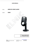
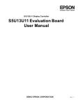
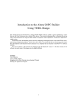
GM01
Hardware Manual V1.0
Hardware Manual
GSM/GPRS MODULE
CHIP-GM01
Order No.
CHIP-GM01
©2009 BECK IPC GmbH
566813
Page 1
GM01
Hardware Manual V1.0
Table of Contents
1 Overview .................................................................................................................... 3 2 Features ..................................................................................................................... 4 3 Pin Description ........................................................................................................... 5 3.1 Digital Interface ............................................................................................................................. 5 3.1.1 3.2 Signal Description .................................................................................................................................... 7 Antenna Connector ....................................................................................................................... 8 4 Interface Description................................................................................................... 9 4.1 4.2 Operating modes .......................................................................................................................... 9 Switching Operating Modes .......................................................................................................... 9 5 Characteristics .......................................................................................................... 10 5.1 5.2 Absolute Maximum Ratings ........................................................................................................ 10 Recommended Operating Ranges ............................................................................................. 10 5.2.1 GSM/GPRS features ............................................................................................................................. 11 6 PCB Board Design ................................................................................................... 12 6.1 Mounting ..................................................................................................................................... 12 6.1.1 Connector .............................................................................................................................................. 12 6.1.2 SIM-Card-Holder ................................................................................................................................... 13 6.1.3 6.2 Spacer ................................................................................................................................................... 14 Power Supply .............................................................................................................................. 14 7 Mechanical Characteristics ....................................................................................... 16 8 Accessories .............................................................................................................. 17 9 Regulatory Information ............................................................................................. 18 9.1 9.2 Declaration of Conformity ........................................................................................................... 19 IC and FCC Compliance for CHIP-GM01 ................................................................................... 20 9.2.1 9.3 10 IC Compliance ....................................................................................................................................... 20 Compliance with RoHS directive ................................................................................................ 21 Guidelines for Efficient and Safe Use .................................................................... 22 10.1 10.2 10.3 10.4 10.5 10.6 10.6.1 General ....................................................................................................................................... 22 Product Care ............................................................................................................................... 23 Radio Frequency Exposure ........................................................................................................ 23 Electronic Equipment .................................................................................................................. 23 Potentially Explosive Atmospheres ............................................................................................ 24 Safety Compliance ...................................................................................................................... 24 Power Supply ........................................................................................................................................ 24 11 Type Approval and Compliance............................................................................. 25 12 History ................................................................................................................... 26 ©2009 BECK IPC GmbH
Page 2
GM01
Hardware Manual V1.0
1
Overview
The CHIP-GM01 from Beck IPC has been developed for an easy integration of GSM/GPRS into industrial
devices.
The provided software API-library is ready to use together with a SC123/SC143 or SC23 only.
The module minimizes the work needed to implement GSM/GPRS in a device as it provides all hardware, type
approval, EMC certification etc. It is developed for reliable, high demanding industrial devices/applications. It
requires no external components except an antenna to transfer an IPC@CHIP into a GSM/GPRS device.
©2009 BECK IPC GmbH
Page 3
GM01
Hardware Manual V1.0
2
Features
• Serial connection
• High performance/throughput
• Supported standards:
• Wide temperature range
• GSM CSD service
• Power save control
• GPRS service
• Short message service (SMS)
©2009 BECK IPC GmbH
Page 4
GM01
Hardware Manual V1.0
3
Pin Description
3.1
Digital Interface
Pin 1
Pin 2
Pin 69
Pin 70
Antenna connector
Figure 3-1: Connectors of the GM01 looking from the bottom side
©2009 BECK IPC GmbH
Page 5
GM01
Hardware Manual V1.0
Signal
Pin
Signal
GND
1
2
GND
GND
3
4
GND
VCC
5
6
VCC
VCC
7
8
VCC
RTS
9
10
USB_VBUS1
RXD
11
12
USB_DP1
DSR
13
14
USB_DN1
CTS
15
16
2
DCD
17
18
2
DTR
19
20
2
TXD
21
22
2
RI
23
24
2
RESET
25
26
2
2
27
28
2
2
29
30
2
2
31
32
2
2
33
34
2
2
35
36
2
2
37
38
2
2
39
40
2
²
41
42
2
2
43
44
SIM_RST
2
45
46
SIM_CLK
2
47
48
SIM_VCC_3V
GPRS
49
50
SIM_PD
IGN
51
52
SIM_DIO
2
53
54
2
2
55
56
2
2
57
58
2
2
59
60
2
2
61
62
2
2
63
64
2
2
65
66
2
2
67
68
2
2
69
70
2
1
not yet supported
2
Reserved for future use, do not connect.
³ All serial signals are logic level.
©2009 BECK IPC GmbH
Page 6
GM01
Hardware Manual V1.0
3.1.1
Signal Description
Signal
Description
I/O
Active
Internal
H/L
PU/PD
Name
Parameter
Conditions
Level
Min.
Typ.
Max.
Unit
3.3
3.6
4.2
V
IMAX
2
A
IOFF
65
µA
2.8
3.0
V
0
0.3
V
Power
GND
VCC
Ground
VIN
DC power
supply
Serial
I
L
TXD
UART TxD
RXD
UART RxD
RTS
UART RTS
CTS
UART CTS
DTR
UART DTR
DSR
UART DSR
O
L
DCD
UART DCD
O
L
RI
UART RI
O
L
SIM
I
L
O
L
I
L
100k
PU
VIH
100k
VIL
2.0
PU
O
L
I
L
100k
PU
VOH
2.6
2.8
V
IOUT≤ 4 mA
VOL
0
0.3
V
2.8
3.0
V
0
0.3
V
2.7
2.85
2.95
V
1.65
1.8
1.95
V
0
0.4
V
VCC
16
V
0
0.4
V
SIM Card
SIM_PD_N
presence
100k
VIH
Per
PU
VIL
ISO 7816-3IC
detect
specifications
O
H
SIM_VCC
SIM supply
SIM_RST_N
SIM reset
O
L
SIM serial
I/O
H
SIM_DIO
data
SIM_CLK
SIM clock
2.0
VOH
VOH
SIM_
VCC
5.1k PU
VOL
O
H
I
H
Control
IGN
Ignition input
Reset signal
RESET_N
age indicator
©2009 BECK IPC GmbH
VIH
2.0
VIL
O
L
output
GPRS cover-
GPRS
15k PU
VOH
IOUT≤ 4 mA
2.6
VOL
O
L
VOH
VOL
2.8
0
IOUT≤ 4 mA
2.6
V
0.3
2.8
0
V
V
0.3
V
Page 7
GM01
Hardware Manual V1.0
Signal
Description
I/O
Active
Internal
H/L
PU/PD
Name
Parameter
Conditions
Level
Min.
Typ.
Max.
Unit
4.5
5.0
5.25
V
0
0.2
V
3.3
3.6
V
0
0.8
V
USB
USB bus
USB_VBUS
3.2
I/O
H
serial data
USB bus
USB_DN
H
power
USB bus
USB_DP
I
VIH
Per USB
VIL
Specification
VIH
Rev. 1.1
3.0
VIL
I/O
serial data
L
VOH
VOL
3.0
3.3
0
V
0.3
V
Antenna Connector
The antenna connector is an RF MMCX-connector. To connect an external antenna, an MMCX to SMA adapter
cable is needed.
©2009 BECK IPC GmbH
Page 8
GM01
Hardware Manual V1.0
4
Interface Description
The main interface of the GM01 is a standard serial connection (UART) with two data-signals, handshake (RTS,
CTS) and status-lines (DTR, DSR). So the GM01 can be handled like any serial interface. The module supports
baud rates from 300 baud to 115,2 kbaud. The serial connection is logic-levelled, using 0-3 VDC.
The reset output is used to indicate a reset of the module. The reset output and the GPRS output can be
connected to any PIO of the SC1x3/SC23, to any other digital logic or left unconnected if not needed.
4.1
Operating modes
The GM01 indicates its operating mode using the PIOs mentioned above.
Mode
Description
Feature
Not Powered
VCC supply is disconnected.
The GM01 is off. Any signals
connected to the interface connector
must be set low or tri-state.
RESET
Valid VCC supply
The GM01 interfaces are off. Any
RESET_N signal is enabled (low)
signals connected to the interface
connector must be set low or tristated.
Idle
RESET_N signal is disabled (high).
The GM01 is fully active, registered
CTS_N and DSR_N signals are
to the GSM network and ready to
enabled (low).
communicate. This is the default
power-up mode.
Sleep
RESET_N signal is high;
The GM01 is in low power mode.
CTS_N signal is disabled.
The application interfaces are
disabled, but GM01 continues to
monitor the GSM network.
GPRS data
RESET_N signal is high,
A GSM/GPRS data transfer is in
progress. When the call terminates,
GM01 returns to the las operating
state (Idle or Sleep).
4.2
Switching Operating Modes
In order to switch the GM01 from RESET mode to Idle mode the IGN pin has to be activated. The new status
(idle) is indicated by the RESET pin and the CTS pin. The RESET pin turns to inactive (high) and the CTS pin is
asserted to low after a short time. The device is switched off by switching IGN back to low. The sleep mode is
entered and left by software.
©2009 BECK IPC GmbH
Page 9
GM01
Hardware Manual V1.0
5
Characteristics
5.1
Absolute Maximum Ratings
Parameter
Min
Max
Unit
Storage Temperature
-40
+85
°C
Supply Voltage (VCC)
0
4.5
V
Digital Input Signals (GM01 powered on);
Except for IGN, VBUS, USB_DP, USB_DN
0
3
V
Digital Input Signals (GM01 powered off);
Except for IGN, VBUS, USB_DP, USB_DN
0
0.2
V
IGN
0
16
V
VBUS
0
5.5
V
USB_DP, USB_DN
0
5
V
Table 5-1: Absolute Maximum Ratings
5.2
Recommended Operating Ranges
(Under operating ranges unless otherwise noted)
Note: Exposure to conditions beyond those listed here may adversely affect the lifetime and reliability of the
device.
Parameter
Min
Supply Voltage (VCC)
3.3
Current consumption
RESET mode
Idle mode
Sleep mode
GPRS Class 10 –
2 TX slot
3 RX slot
Max. TX burst current
Operating temperature
Typ
Max
Unit
4.2
V
µA
mA
mA
mA
50
20
3.3
500
mA
2000
-20
+75
°C
Table 5-2: Recommended Operating Ranges
©2009 BECK IPC GmbH
Page 10
GM01
Hardware Manual V1.0
5.2.1
GSM/GPRS features
Parameter
Data
RF output power max. GSM 850/900
Class 4, max. 33 ± 2 dBm
RF output power max. DCS 1800/PCS1900
Class 1, max. 30 ± 2 dBm
GPRS
Multi-slot class 10 (4 Rx/2 Tx/5 Sum)
Max downlink BR 85.6 kbps
Coding scheme CS1-CS4
CSD
Max BR 14.4 kbps
SMS
MO/MT Text and PDU modes
Cell broadcast
Character Sets
UTF8
UCS2
ASCII
GSM
8859-1
Status-Indicators
GSM/GPRS coverage
Reset
Table 5-3: GSM features
©2009 BECK IPC GmbH
Page 11
GM01
Hardware Manual V1.0
6
PCB Board Design
6.1
Mounting
6.1.1
Connector
One-Piece Interface – Board to Board connector
Dimensions:
Beck Order No.:
Molex Order No.:
A: 17 mm
B: 17.7 mm
C: 21.3 mm
567527 (CHIP-GM-EMC01)
52991-0708
Layout Suggestion:
©2009 BECK IPC GmbH
Page 12
GM01
Hardware Manual V1.0
6.1.2
SIM-Card-Holder
A 100 nF capacitor shall be placed at SIM_VCC line next to the SIM-card-holder.
A 56 Ohm series resistor shall be placed in the SIM_DIO line.
A 100 Ohm series resistor shall be placed in the SIM_CLK line.
Schematic example:
A SIM-Card-Holder is available at BECK:
Beck Order No.: 567529 (CHIP-GM-SIM01)
FCI:
7111S1615A02LF
Layout Suggestion:
©2009 BECK IPC GmbH
Page 13
GM01
Hardware Manual V1.0
6.1.3
Spacer
For proper mechanical fixation two spacers are needed. They are soldered to the PCB and provide metric
thread M3.
Dimensions:
A: 4.0 mm
B: 5.0 mm
L: 3.0 mm
M: M3
Beck Order No.:
567528 (CHIP-GM-SP01)
MAC8 Order Number:
2SSA-3.0
6.2
Power Supply
Special care must be taken when designing the power supply of the GM01. The single external DC power
source indirectly supplies all the digital and analog interfaces, but also directly supplies the RF power amplifier
(PA). Therefore, any degradation in the power supply performance, due to losses, noises or transients, will
directly affect the GM01 performance.
The burst-mode operation of the GSM transmission and reception, draws instantaneous current surges from the
power supply, which causes temporary voltage drops of the power supply level. The transmission bursts
consume the most instantaneous current, and therefore cause the largest voltage drop. If the voltage drops are
not minimized, the frequent voltage fluctuations may degrade the GM01 performance.
Transmission power drops
It is recommended that the voltage drops during a transmit burst will not exceed 300mV, measured on the G24L interface connector. In any case, the G24-L supply input must not drop below the minimum operating level
during a transmit burst. Dropping below the minimum operating voltage may degrade the module performance.
©2009 BECK IPC GmbH
Page 14
GM01
Hardware Manual V1.0
To minimize the losses and transients on the power supply lines, it is recommended to follow these guidelines:
• Use a 1000 uF, or greater, low ESR capacitor on the G24-L supply inputs. The capacitor should be located as
near to the G24-L interface connector as possible.
• Use low impedance power source, cabling and board routing.
• Use cabling and routing as short as possible.
Capacitor
1000 uF
Usage
GSM Transmit current surge
10 nF, 100 nF
Digital switching noise
8.2 pF, 10 pF
33 pF, 39 pF
1800/1900 MHz GSM EMI
850/900 MHz GMS EMI
©2009 BECK IPC GmbH
Description
Minimizes power losses during transmit bursts.
Use maximum possible value.
Filters digital logic noisesfrom clocks and data
sources
Filters transmission bands
Filters transmission bands
Page 15
GM01
Hardware Manual V1.0
7
Mechanical Characteristics
GM01
©2009 BECK IPC GmbH
Page 16
GM01
Hardware Manual V1.0
8
Accessories
Accessory
Description
Pigtail: MMCX to
SMA adapter cable
Antenna: SMA M
90 dgr
©2009 BECK IPC GmbH
Approval for use in
USA and Canada
Manufactur / Order
No.
Cable length 130mm
no
2J antenna
conceptor /
C05C88-015
130mm
vertical polarization, +2.2dBi
gain, size 96.5 mm, SMA male
connector 90°
no
2J antenna
conceptor /
2J010
Page 17
GM01
Hardware Manual V1.0
9
Regulatory Information
The G24-L module is compliant with applicable FCC, IC and European R&TTE requirements. The
integrated system incorporating the GM01 module may be subject to further regulations and
standards. Motorola strongly recommends that the system integrator seeks professional advice
regarding the regulations and standards that apply to their product.
The Federal Communications Commission (FCC) requires application for certification of digital
devices in accordance with CFR Title 47, Part 2 and Part 15. This includes Electromagnetic Energy
Exposure (EME) testing. As the GM01 modem is not a standalone transceiver but is an integrated
module, the GM01 cannot be tested by itself for EME certification. It is, however, the integrator’s
responsibility to have the completed device tested for EME certification.
The module is compliant to European R&TTE directive requirements; however the complete system
(host plus GM01 module) may be subject to R&TTE or other directives (for instance the EMC
directive 2004/108/EC). Motorola strongly recommends that the system integrator seek professional
advice regarding the applicable standards and directives, and most efficient route to demonstrating
compliance, and required product markings.
The GM01 module is compliant to FCC, IC and R&TTE requirements allowing use within Europe
and North America. Use in other regions may require regional "type approvals" which the
manufacturer of the final product integration or reseller will be responsible for procuring. Many
regional type approvals are based upon compliance to FCC, R&TTE, ETSI and other standards that
the GM01 is compliant with. It is strongly recommended that professional advice be sought before
placing the finished integrated product on the market to establish local approval and marking
requirements.
©2009 BECK IPC GmbH
Page 18
GM01
Hardware Manual V1.0
9.1
Declaration of Conformity
We, Beck IPC GmbH
Grüninger Weg 24
35415 Pohlheim-Garbenteich, Germany
declare under our sole responsibility that our product:
CHIP-GM01 (566813)
to which this declaration relates, conforms to the following product specifications:
R&TTE Directive 1999/5/EC
The following harmonized standards and normative documents are those to which the product’s conformance is
declared, by specific reference to the essential requirements of Article 3 of the directive.
Article 3.1.a:
Not applicable for this type of product.
Article 3.1.b:
EN 301 489-1
EN 301 489-7
Article 3.2:
EN 301 511
02.02.09 Pohlheim-Garbenteich, Germany
____________________________
Thomas Schumacher
Business manager of Beck IPC GmbH
©2009 BECK IPC GmbH
Page 19
GM01
Hardware Manual V1.0
9.2
IC and FCC Compliance for CHIP-GM01
9.2.1
IC Compliance
The following paragraphs must be addressed by the integrator to ensure their host is in compliance
to the GM01 FCC grant and/or the FCC grant of the host device.
CFR 47 Part 15.19 specifies label requirements
The following text may be on the product, user's manual, or container.
This device complies with Part 15 of the FCC Rules. Operation is subject to the following two
conditions:
(1) this device may not cause harmful interference, and
(2) this device must accept any interference received, including interference that may cause undesired
operation.
CFR 47 Part 15.21 Information to user
The user's manual or instruction manual for an intentional or unintentional radiator shall caution the
user that changes or modifications not expressly approved by the party responsible for compliance
could void the user's authority to operate the equipment. In cases where the manual is provided only
in a form other than paper, such as on a computer disk or over the Internet, the information required
by this section may be included in the manual in that alternative form, provided the user can
reasonably be expected to have the capability to access information in that form.
CFR 47 Part 15.105 Information to the user
(b) For a Class B digital device or peripheral, the instructions furnished the user shall include the
following or similar statement, placed in a prominent location in the text of the manual:
Note: This equipment has been tested and found to comply with the limits for a Class B digital
device, pursuant to Part 15 of the FCC Rules. These limits are designed to provide reasonable
protection against harmful interference in a residential installation. This equipment generates, uses
and can radiate radio frequency energy and, if not installed and used in accordance with the
instructions, may cause harmful interference to radio communications. However, there is no
guarantee that interference will not occur in a particular installation. If this equipment does cause
harmful interference to radio or television reception, which can be determined by turning the
equipment off and on, the user is encouraged to try to correct the interference by one or more of the
following measures:
- Reorient or relocate the receiving antenna.
- Increase the separation between the equipment and receiver.
- Connect the equipment into an outlet on a circuit different from that to which the receiver is
connected.
- Consult the dealer or an experienced radio/TV technician for help.
Note: The unit must be installed in a manner that provides a minimum separation distance of 20 cm
or more between the antenna and persons and must not be co-located or operate in conjunction with
any other antenna or transmitter to satisfy FCC RF exposure requirements for mobile transmitting
devices.
9.2.1.1
Antenna
The module type CHIP-GM01 is for OEM integrations only. In the end-user product the module shall be
professionally installed in such a manner that only the authorized antennas can be used.
Antenna Installation
• The antenna installation must provide a minimum separation distance of 20 cm from users and nearby
persons and must not be co-located or operating in conjunction with any other antenna or transmitter.
©2009 BECK IPC GmbH
Page 20
GM01
Hardware Manual V1.0
• The combined cable loss and antenna gain must not exceed +6.8 dBi (850 band). The combined cable loss
and antenna gain must not exceed +2.2 dBi and total system output must not exceed 2.0W EIRP in the PCS
(1900) band in order to comply with the EIRP limit of 24.232 (b). OEM installers must be provided with antenna
installation instruction and transmitter operating conditions for satisfying RF exposure compliance.
• For system integrations requiring higher antenna gain, or position closer than 20cm from the body, SAR
compliance testing of the completed product will be required. It is strongly recommended that the system
integrator seeks the advice of a suitably accredited test laboratory to develop a test plan and carry out
necessary testing.
9.2.1.2
Caution
Any changes or modifications NOT explicitly APPROVED by BECK IPC could cause the module to cease to
comply with FCC rules part 15, and thus void the user’s authority to operate the equipment.
9.3
Compliance with RoHS directive
The CHIP-GM01 is produced according to the RoHS (Restriction of the use of certain Hazardous Substances in
electrical and electronic equipment) directive and complies with the directive.
©2009 BECK IPC GmbH
Page 21
GM01
Hardware Manual V1.0
10 Guidelines for Efficient and Safe Use
10.1 General
Read this information before using your GM01 module.
Note: Changes or modifications to the product not expressly approved by Beck IPC GmbH will void the
user’s authority to operate the equipment.
The following general safety precautions must be observed during all phases of operation, service, and repair of
the equipment described in this manual. Failure to comply with these precautions or with specific warnings
elsewhere in this manual violates safety standards of design, manufacture, and intended use of the equipment.
Motorola, Inc. assumes no liability for the customer’s failure to comply with these requirements. The safety
precautions listed below represent warnings of certain dangers of which we are aware. You, as the user of this
product, should follow these warnings and all other safety precautions necessary for the safe operation of the
equipment in your operating environment.
Ground the instrument
Only suitably qualified individuals should work on the product and host system. Consideration should be given
to the safest grounding arrangement for the host application.
Do not operate in an explosive atmosphere
Do not operate the equipment in the presence of flammable gases or fumes. Operation of any electrical
equipment in such an environment constitutes a definite safety hazard.
Do not service or adjust alone
Do not attempt internal service or adjustment unless another person, capable of rendering first aid is present.
There are no user serviceable parts inside the GM01 module.
Keep away from live circuits
Operating personnel must:
• not remove equipment covers. Only Factory Authorized Service Personnel or other qualified maintenance
personnel may remove equipment covers for internal subassembly, or component replacement, or any internal
adjustment
• not replace components with power cable connected. Under certain conditions, dangerous voltages may exist
even with the power cable removed
• always disconnect power and discharge circuits before touching them
Do not substitute parts or modify equipment
Because of the danger of introducing additional hazards, do not install substitute parts or perform any
unauthorized modification of equipment. Contact Motorola Warranty and Repair for service and repair to ensure
that safety features are maintained.
©2009 BECK IPC GmbH
Page 22
GM01
Hardware Manual V1.0
10.2 Product Care
•
Do not expose your product to liquid or moisture.
•
Do not expose your product to extreme hot or cold temperature (see section 5.2 for further information)
•
Do not expose your product to lit candles, cigarettes, cigars, open flames, etc.
•
Do not drop, throw or try to bend your product since rough treatment could damage your product.
•
Do not attempt to disassemble your product. Doing so will void warranty. The product does not contain
consumer serviceable or replaceable components. Service should only be performed by Beck IPC.
•
Do not paint your product as the paint could prevent normal use.
•
If you will not be using your product for a while, store it in a place that is dry, free from damp, dust and
extreme heat and cold.
•
The cooling of the end product shall not negatively be influenced by the installation of the module.
10.3 Radio Frequency Exposure
The GM01 module contains a small radio transmitter and receiver. During communication via GPRS/PSM the
GM01 Module receives and transmits radio frequency (RF) electromagnetic fields (microwaves) in the
frequency range 800 to 1900 MHz. The output power of the radio transmitter is very low.
When using the GM01 module, you will be exposed to some of the transmitted RF energy. This exposure is well
below the prescribed limits in all national and international RF safety standards and regulations.
10.4 Electronic Equipment
Most modern electronic equipment, for example, in hospitals and cars, is shielded from RF energy. However,
certain electronic equipment is not. Therefore:
Note: This equipment emits RF energy in the ISM (Industrial, Scientific, Medical) band. Please insure that all
medical devices used in proximity to this device meet appropriate susceptibility specifications for this type of RF
energy.
©2009 BECK IPC GmbH
Page 23
GM01
Hardware Manual V1.0
10.5 Potentially Explosive Atmospheres
Turn off your electronic device before entering an area with potentially explosive atmosphere. It is rare, but your
electronic device could generate sparks. Sparks in such areas could cause an explosion or fire resulting in
bodily injury or even death.
Areas with a potentially explosive atmosphere are often, but not always, clearly marked. They include fuelling
areas, such as petrol station, below deck on boats, fuel or chemical transfer or storage facilities, and areas
where the air contains chemicals or particles, such as grain, dust, or metal powders.
10.6 Safety Compliance
In order to fulfil the safety standard EN 60950-1:2001 the CHIP-GM01 must be supplied by a Class-2 Limited
Power Source.
10.6.1 Power Supply
TheGMT01 module must be supplied by a limited power source according to EN 60950-1.
•
Connect your power supply only to designated power-sources as marked on the product.
•
Make sure all cords and cable are positioned so that they will not be stepped on, tripped over or otherwise
subject to damage or stress.
•
To reduce risk of electric shock, unplug the unit from any power source before attempting to clean it.
©2009 BECK IPC GmbH
Page 24
GM01
Hardware Manual V1.0
11 Type Approval and Compliance
Type Approval
» R&TTE (Europe)
» FCC/CFR 47 part 15,22 ,24
» IC (Industry Canada)
» GCF 3.27.1
» NAPRD 3.14.0
Certifications and Compliance
» R&TTE - LVD 2006/95/EC
EMC Directive: 89/336/EEC
» EN 301 489-1
» EN 301 489-7
Safety compliance
» EN 60950
©2009 BECK IPC GmbH
Page 25
GM01
Hardware Manual V1.0
12 History
Revision
Date
Author
Comments
V0.00
V0.1
V1.0
18.11.2008
12.03.2009
24.04.2009
T. Kurth
T. Kurth
T. Kurth
initial version
TXEN removed, minor changes
First release
IGN added at 3.1
© 2000-2009 BECK IPC GmbH All rights reserved. No part Life critical applications — These products are not designed for
of this document may be copied or reproduced in any form or by use in life support appliances, aeronautical applications or
any means without the prior written consent of BECK IPC devices or systems where malfunction of these products can
GmbH. The information in this document is subject to change reasonably be expected to result in personal injury.
without notice. Devices sold by BECK IPC GmbH. Are covered Right to make changes — BECK IPC GmbH reserves the right
by warranty and patent indemnification provisions appearing in to make changes, without notice, in the products, including
BECK IPC GmbH. Terms and Conditions of Sale only. BECK software, described or contained herein in order to improve
IPC
GmbH
MAKES
NO
WARRANTY,
EXPRESS, design and/or performance. Beck IPC GmbH assumes no
STATUTORY, IMPLIED OR BY DESCRIPTION, REGARDING responsibility or liability for the use of any of these products.
THE INFORMATION SET FORTH HEREIN OR REGARDING
THE FREEDOM OF THE DESCRIBED DEVICES FROM
INTELLECTUAL PROPERTY INFRINGEMENT. BECK IPC
GmbH MAKES NO WARRANTY OF MERCHANTABILITY OR
FITNESS FOR ANY PURPOSE.
BECK IPC GmbH Shall not is responsible for any errors that
may appear in this document. BECK IPC GmbH makes no
commitment to update or keep current the information
contained in this document.
©2009 BECK IPC GmbH
Page 26