1
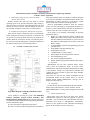
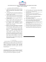
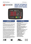
ISSN 2249-6343 International Journal of Computer Technology and Electronics Engineering (IJCTEE) Volume 3, Issue 2, April 2013 An Embedded1/3 Phase Automatic Transfer Switch Controller with Intelligent Energy Management Autade Prerana P., S. G. Galande Just as a facility with a generator set usually has the equipment to automatically detect problems and respond, the utility distribution system includes equipment to automatically detect the problem and return power to their customer as fast as is practical. These systems may re-route the power from anther source, or may attempt to re-feed the failed part of the system. In many cases the damaged part of the system is isolated so quickly that customers don‟t even notice a problem[3]. Abstract— “PROTOGEN” is a 3-phase Automatic/Manual Generator Controller module that includes protection for GEN-SETS. Use of advanced micro controller in the design platform provides easy and trouble free control and operation mechanism of GEN-SETS in case of failure of mains power. Upon failure of mains power (due to faults like loss of power, over voltage, under voltage, phase reversal, phase unbalance etc.), “PROTOGEN” initiates “Automatic GEN-SET Start Cycle” including transfer of load to GEN-SET by using the Generator contactor. As and when the mains power gets restored, the load gets automatically transferred back to the mains line and the GEN-SET stops after a cool-down time. During the cycles, the GEN-SET is protected against malfunction. All alarms occurring at abnormal GEN-SET conditions are computed and displayed either by LED or on LCD through alphanumeric messages. II. TRANSFER SWITCH OPERATION There are wide varieties of transfer switches available, though many different manufactures. Variations that are available include manual operation, automatic open transition and closed transition operation sequences (some with mechanical bypass capability), closed transition load ramping devices, and solid-state types. The most common type of ATS, and the one we will look at in detail is an automatic electro-mechanical device that operate in an open transition sequence.”Open Transition” means that the switch disconnect load from one source before it connects to another source. So, whenever the transfer switch operate from source to source there is short (fraction of second) power failure. The timing function and setting practice discussed in this document will be applicable for most types of transfer switches.[1] Keywords-ATS (Automatic Transfer switch), LCD (Liquid crystal display), LED (Light emitting diode). I. INTRODUCTION A typical stand by power system includes a generating set operating on diesel, fuel or natural gas and one or more automatic transfer switches. The system will also have a number of accessory components such as battery charging equipment, fuel pumps, ventilation fans, and other equipments. The transfer switches direct power to critical loads from either a utility service or your generator set. Most „failures‟ in the utility power supplied to facility are not failures of the large central stations providing power, but rather failures in power distributions system serving the facility. Failures can occur due to damage the part of utility system, failure of distribution component, or overload of distribution system. For example, if a car drives of the road and knocks down a power pole, it‟s not surprise that customers who are served by the lies on that power pole will have a disruption in power. However all the customers affected by the downed line may not have to wait until the line is repaired to get power back. A. ATS Setting for best operation First, recognize that it is normal for voltage of the power service to your home or facility varies somewhat over time and is different in different location. So, if you set up a transfer switch to start the generator set at 90% of normal level, it might start a lot of times! Also, the typical voltage level at your home or facility varies over time depending on a number of other conditions. It‟s possible that it might normally be a little higher or a little lower than the nominal 120 volt level that is intended. That won‟t cause any problem, but it should be considered in the decision of how to set up your transfer switch. 12 ISSN 2249-6343 International Journal of Computer Technology and Electronics Engineering (IJCTEE) Volume 3, Issue 2, April 2013 Determine if the transfer switch serves emergency loads, ifdo, you need to get a problem sensed quickly, and the ATS must connect to the sensed quickly, and the ATS must connect to the genset in 10 second or less. A key factor in the setting is how long it takes to get the generator set started and up too proper speed and voltage. This varies somewhat with the size normal service after a preset time delay, most transfer switches can be set up to stay connected to the generator set until an operator signals that retransfer can be done. These facilities include loads that are sensitive to perform the retransfer to normal power, the loads are not disrupted at a when users will notice the problem. Fig1.A 4-pole transfer switch incorporates a switched B. Pre-Transfer signals for best operation neutral, while a 3-pole ATS has a solid neutral[8]. Some loads, such as elevator and some types of cash register D. Frequency sensing systems are disrupted when there is a sudden loss of power and a Frequency sensing is normally provided on the generator short time later, a sudden return of power. For example, if you source for the purpose of monitoring of an ATS so that the user have ever been in an elevator when [power fails, you know that can be sure that the generator set is operating at the proper speed the elevator immediately stops, and the stopping point may ell be between floors. If the elevator control system is confused by prior to connecting loads. Most modern generator set the sudden failure in power in power or return of power. A automatically adjust voltage as a function of speed, making it signal to tell the elevator controller that the ATS is about to unlikely that the generator set will operate at improper voltage operate can allow the elevator to move to the next available and improper speed, but some codes still require this feature. control, open the doors and wait. Then while the power is failed Frequency sensing is also available as an optional feature for no one is trapped in the elevator. The power can then turn off utility source. This feature is primarily designed for application without incident. The pre=-transfer signal is also used if the where there is a weak utility grid.(A weak utility grid is one in transfer switch operate too quickly from live source to live which the grid is relatively low in capacity relative to the largest source. Again, the signal allows the load to turn off, the switch loads in the system. In a weak grid environment frequency to operate, and then the load can turn on again without causing variation will occur which are not present in stiff grid system, disruption in the facility distribution system or damaged to the such as a common in North America.) Frequency sensing on the loads. utility source can be used to detect potentially disruptive frequency swing on a weak grid, or as another factor in C. Switched neutral (4-pole) Transfer switches qualifying source acceptability. Transfer switches that serve three-phase/four-wire loads can be E. Programmed Transition either 3-pole or 4-pole (switched neutral) type transfer switches. The physical differences between 3-pole and 4-pole transfer Transfer switches that serve large motor loads (greater than switches are shown in the illustration below. In a 4-pole transfer 20Hp), UPS, and other inductive loads are often provided with switch, all the phase poles plus the neutral are provided with programmed transition capability. When inductive load are power transfer contacts. In a 3-pole transfer switch, the neutral disconnected from a power source, they produce output voltage does not utilized power transfer contacts, but rather is provided for a short period of time. If the ATS switches too quickly from with a solid bus-bar connection point.4-pole transfer switches source to source, the load generated voltage is parallel to the out are used in 277/480VAC application where the facility power coming source voltage. Interconnecting voltages from multiple distribution system incorporate ground fault protection. sources that are not synchronized will cause damage to loads, and nuisance tripping of circuit barkers. To prevent this problem, the transfer switch operating speed from source to source is intentionally slowed down, so that the load generated voltage delay to a safe level before they are connected to the new source. 13 ISSN 2249-6343 International Journal of Computer Technology and Electronics Engineering (IJCTEE) Volume 3, Issue 2, April 2013 F. Phase angle sensing between sources (In-phase shows the measured values on its displays. The unit is designed monitor, phase check) to provide user friendliness for both the installer and the user. Programming is usually unnecessary, as the factory settings Transfer switches that don‟t have the ability to control have been carefully selected to fit most applications. operating speed can be provided with phase angle sensing to However programmable parameters allow the complete allow the sources to drift into synchronization before the ATS control over the generating set. Programmed parameters are switches between live sources. This can mitigate the effects of stored in a Non Volatile Memory and thus all information is fast switching of inductive loads, but is not 100% effective. retained even in the event of complete loss of power. G. Automated exercising(tests ATS and exercise genset) In my Project, I am basically concentrating on following Most transfer switches incorporate timers to automatically applications such as initiate testing and exercising of a generator set. Generator sets Display of 3 phase Generator voltage, frequency and are typically exercised (run under load) once per month for 30 RPM,3 phase mains voltage,3 phase load current, date minutes. When the ATS load is used for exercising the genset, and time, KWH for mains and DG set, power factor of the exercise provide the dual purpose of testing the operation of R,Y,B phases, fault log data, DG start-stop events, DG the transfer switch so this is recommended practice. Battery voltage 39 programmable parameters(programming protected III. SCHEME OF IMPLEMENTATION with password ) Programmable current transformer ratio Programmable site code 11 Digital inputs, 12 Relay outputs Relay outputs for mains and generator contactor Fuel consumption per liter Log of Fuel consumption(optional) Remote monitoring of parameters-RS232 upon request A. Operation “PROTOGEN” has two basic operation modes, namely AUTO mode and MANUAL mode. In AUTO mode, “PROTOGEN” controls the GEN-SET automatically according to the parameter settings. Two push buttons (“START” and “STOP”) have been provided to operate the engine manually (MANUAL mode). Auto mode: To enter into the AUTO modeSwitch ON the Auto/Manual Switch of the Control Panel to “AUTO” Position.“AUTO MODE OPERATION.” message will be displayed on the LCD.[5,6] B. Auto mode: To enter into the AUTO modeSwitch ON the Auto/Manual Switch of the Control Panel to “AUTO” Position.“AUTO MODE OPERATION.” message will be displayed on the LCD [5,6]. Fig2: Block diagram of embedded automatic transfer switch I have decided to develop the system “An Embedded 1/3Phase Automatic Transfer Switch Controller with Intelligent Energy Management”because my aim of the paper is to automate the Generating Set with Programming Parameters accessed from Remote place. So, I have decided it to implement protogen unit. The unit is a control and protection panel used in gensets. It C. Failure of Mains Power: When mains power fails due to any fault in the system, “PROTOGEN” initiates an auto-start sequence to start the GEN-SET. After successful start of the GEN-SET, the load is transferred from mains to “PROTOGEN” automatically. However, in case of phase reversal, “Phase Reverse Message” appears on the LCD for corrective action.[5,6] 14 ISSN 2249-6343 International Journal of Computer Technology and Electronics Engineering (IJCTEE) Volume 3, Issue 2, April 2013 D. Starting Sequence: The generator cool-down time will start thereafter. During the cool-down period the generator will run without load.[5,6] Crank will given to generator. The LCD will display START MODE……..”Message. If the Generator starts within the F. MANUAL MODE: number of attempts set in the program (programming parameter The “PROTOGEN” unit is by default on MANUAL mode no.8), the load will get shifted to the Generator. If the Generator when power is ON. To enter in MANUAL mode, switch on the does not start within the programmed number of attempts, “Auto/Manual Switch” of the Control Panel to MANUAL “FAIL TO START” message will be displayed for corrective position. “MANUAL MODE OPERAT.” message will be action. [5,6] displayed on the LCD. In MANUAL mode, the GEN-SET can E. Restoration of Load To Mains Power: be started and stopped by means of two push buttons “START” and “STOP” on the front panel. The start/stop sequence relates When mains supply returns to normal condition, to the parameter settings.[5,6] “PROTOGEN” will transfer the load automatically from generator to mains after “mains restore time” (programming parameter no.4), through the mains contactor. Fig3. Flowchart For Embedded ATS Switch 15 ISSN 2249-6343 International Journal of Computer Technology and Electronics Engineering (IJCTEE) Volume 3, Issue 2, April 2013 Table 1: Program Parameters: Para. No. 1. 2. 3. 4. 5. 6. 7. 8. 9. 10. 11. 12. 13. 14. 15. 16. 17. 18. 19. 20. 21. 22. 23. 24. 25. 26. 27. 28. 29. 30. 31. 32. 33. 34. 35. Details of Parameters Range Standard Mains Low Voltage Mains High Voltage Engine Start Delay Mains Restore Time LLOP Bypass Time Stop Solenoid Time Crank Time Crank Attempts Crank Rest Time Engine Cooling Time Engine Warm-up Time DG Low Voltage DG High Voltage DG Max Run Time DG Low Frequency DG High Frequency Over Load Current Load C.T. Ratio Phase Unbalance Device ID Remote Start Remote Stop GSM Modem Event ReportingThrough Modem Engine Preheat Time Engine Periodic Start Engine Rest Time Engine Periodic Run Set Low Battery Volt Set Hooter Timeout Change password Alphanumeric Site ID Setting Options DG Stop option LCD Back light options: 90 –210 Volts 250 -285 Volts 0 - 3600 Sec 0 – 300 Sec 0 – 99 Sec 10 – 99 Sec 1 – 99 Sec 1-5 1 – 99 Sec 0 – 300 Sec 0 – 300 Sec 170 270 5 15 15 25 3 3 15 60 10 180 – 210 Volts 250 – 285 Volts 0 – 1440 min ;0- Disable 43 – 47 Hz 53 – 59 Hz 0 – 1000 AMP 1 – 1000 Ratio 10 – 100 Volts 0- 255 Yes – Enable; No - Disable Yes – Enable; No - Disable Yes – Enable; No - Disable Report all Event; Report Fault Event; Disable 0 – 300 Sec 0 – 90Days 0 – 10 Hrs 0 – 300 Minutes 8.0V- 24.0V 0-900sec (0-Disable) 0 - 9999 20 digit; Can set 0-9-A-Z Delete/Reset Option, PC To Unit Copy ETS/ETR Continuous ON/Power saving mode. 36. 37. 38. 39. Mains Failure Time Configuration Of DI3 input Oil sensor / wiring fault alarm Mains Fail alarm 0 – 250 Sec Door open or Fire/smoke input On Or OFF On Or OFF 16 190 265 0 46Hz 53 30 1 50 32 No No No Disable 0 0 0 0 10.0v 120sec 1000 ETS Continuous ON 6 Sec Fire/smoke ON OFF ISSN 2249-6343 International Journal of Computer Technology and Electronics Engineering (IJCTEE) Volume 3, Issue 2, April 2013 IV. APPLICATIONS OF ATS SWITCH 1) 2) 3) 4) 5) 6) A multinational bank operations center performing critical 7 x 24 operations cannot sustain an outage without substantial losses and disruption to global operations. A telecommunications site that hosts multitudes of users cannot go down without loss of revenues and credibility with its customers. A boiler control system of a power plant supporting a major manufacturing operation cannot be disabled without substantial cost of recovery and degradation of product quality. Loss of power to computers and display systems at a major air traffic control center poses risks to passenger safety as well as causing flight delays. Loss of power to systems controlling tools, ovens, and apparatus that manufacture intricate microelectronics can cause lost product, delays in shipment, and loss of quality. Home use of transfer switch-homes with standby generator may use a transfer switch for a few circuits or the whole home. Different models are available, with both manual and automatic transfer. Often small transfer switch system use circuit breakers with an external operating linkage as the switching mechanism. The linkage operates two circuit breakers in tandem, closing one while opening the other. Manufactures of transfer switches can provide recommended installation procedures. Like all other electrical apparatus, local electrical codes require transfer switches to carry safety approvals. However, some transfer switches are sold via the Internet, and there have been problems with counterfeit circuit breakers. V. CONCLUSION The aim of paper is to present embedded ATS switch and highlights their use in industry, mobile tower applications. It has been underlined that this hardware solution can perfectly address the current challenges in these fields such as high control performance, reliability and efficiency. Programmable parameters allow the complete control over the generating set. ACKNOWLEDGMENT This project sponsored by Cologicx Systems Private Limited, Embedded Business Solution. Author would like to thank Mr. Wasudev Deshmukh,Chief Manager for their support and involving in the discussion throughout the experiment. REFERENCES An article on “Energy conservation in India” by Shri P M Sayeed, Hon‟ ble Minister of Power‟ s article on the occasion of Energy Conservation Day, on 14th December 2005. [2] Y.Sung Song,K.Deok Moon.”Home Energy Management System Based on Power line communication”.978-1-4244-4316-1/10IEEE2010. [3] Yong Hua Song and Allan T Johns”Flexible ac transmission System “The Institution of Electrical Engineers, London, Uniited Kigdom1999. [4] Hingarani, N.G.”High power Electronics and Flexible AC Transmission System”, Power Engineering Review, IEEE, Volume: 8.Issue:7, July1988, pages3-4. [5] Barnini, Datakom User Manual. [6] Utopia Automation and control Pvt.Ltd. User operation manual. [7] Anoop R, Anup J Nambiar, Prathap R, Sridhar Divakar, Dr. T B Isha “Condition monitoring of Diesel generator using PC”. [8] Paper on “Automatic transfer switch (ATS) based on a programmable logic controller (PLC)”, Mechatronics, 2004, ICM '04. Proceedings of the IEEE International Conference, Issue: 3-5 June 2004,pages:531-535. [9] High voltage high-speed vacuum automatic transfer switch (ATS), Harmonics and Quality of Power, 2000 Proceedings, Ninth International Conference, Issue2000,volume:3,pages:882-886. [10] Book entitled by “Maintaining Mission Critical Systems in a 24/ Environment”, Publisher: Wiley-IEEE Press, Pages: 89 -111, Subject Categories: Power, Energy, & Industry Applications. [1]