1
DPS32 Driver Pack Features
• Bilevel Drive Operation
• 100 Watt Transformer 110/220V Operation
• 110/220V Operation
• Short Circuit Protection
• Open Motor Protection
• Fault LED
• 5 Amps/Phase Operating Current
• 3.5 Amps/Phase Output Current
• Unipolar Operation
• Half-Step and Full-Step Operation
• Motor On/Off Input
• No RFI or EMI Problems
• TTL/CMOS Compatible Inputs
• Optional +5VDC Regulated and +12 Unregulated Voltage Supply, order Model DPS32PS1
General Description
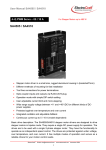
The Anaheim Automation DPS32001 is a step motor Driver Pack that can drive motors rated from 0.5 to 3.5
amp/phase (unipolar rating). DPS32001 can handle 6-lead and 8-lead motors. This Driver Pack features
a unipolar bilevel (or dual voltage) drive technique with short/open circuit protection (with a Fault LED).
Outstanding motor performance is provided by means of a Bilevel Drive technique. The DPS32001’s
open frame construction is ideal for OEM because of it’s cost-effective design.
Bilevel Drive
The basic function of a motor driver is to provide the rated motor phase current to the motor windings
in the shortest possible time. The bilevel driver uses a high voltage to get a rapid rate of current rise in
the motor windings in the least amount of time. When reaching the preset trip current, the driver turns
off the high voltage and sustains the current from the low voltage supply.
Excitation Mode Select
Users have a choice of dual-phase, full-step operation or half-step operation. Dual-phase, full-step operation occurs by energizing two phases at a time, rotating a typical motor 1.8 degrees per step. Halfstep operation occurs by alternately energizing one, and then two, phases at a time, rotating the motor
0.9 degrees per step. Full-step operation is only suggested for applications that specifically require that
mode, such as when retrofitting existing full-step systems.
Step and Direction Control
Clock and Direction, or Dual Clock operation. The Direction Input or CCW Input can be selected by
placing jumpers in the appropriate positions (see Table 2). Pulses applied to the Clock input cause the
motor to step in the clockwise direction if the Direction Input is a logic “1” or the counterclockwise direction if the Direction Input is a logic “0”. Pulses applied to the CCW Input cause the motor to step in the
counterclockwise direction. Either positive or negative going pulses may be used by setting jumpers to
the appropriate positions (See Table 2).
L010041
January 2013