1
Manual
Frequency Inverter Vector 54 WT
- 33
__________________________________________________________________________________
User manual
Frequency Inverter VECTOR 54 WT
Frequency Inverter for heat recovery
Rev. 10/2013
Date: 21.10.2013
21.10.2013
Manual
Frequency Inverter Vector 54 WT
- 34
__________________________________________________________________________________
Warranty
According to the current general terms of delivery and payment MSF- Vathauer Antriebstechnik
GmbH & Co. KG provides a warranty of 12 months (in single shift) after delivery on all electronic
devices covering design, material or faulty workmanship.
MSF- Vathauer Antriebstechnik reserves the right to change the contents of this operation manual
and the product specifications contained therein without prior notice.
The copyright of this documentation is reserved by
MSF-Vathauerer Antriebstechnik GmbH & Co. KG .
21.10.2013
Manual
Frequency Inverter Vector 54 WT
- 35
__________________________________________________________________________________
Table of Contents
1. Short form of the connection diagram version Hoval ........................................................................38
1.1 Terminal allocation scheme of the control inputs ..........................................................38
1.2 Control Signal ................................................................................................................39
1.3 Rev setting......................................................................................................................39
1.4 Setting of the rolling direction .......................................................................................39
1.5 Rotor start/stop ...............................................................................................................39
1.6 Release and reset ............................................................................................................39
1.7 Rotor run supervision (B1).............................................................................................40
1.8 Thermo safety contact Engine........................................................................................40
1.9 Failure message ..............................................................................................................40
1.10 Message state of readiness ...........................................................................................40
1.11 Precedence speed .........................................................................................................40
2. Safety and application instructions for the frequency-inverter ..........................................................41
2.1 Danger ............................................................................................................................41
2.2 Intended Usage...............................................................................................................41
2.3 Transport and Storage ....................................................................................................41
2.4 Installation......................................................................................................................42
2.5 Electrical connection ......................................................................................................42
2.6 Operation........................................................................................................................42
2.7 Maintenance and servicing.............................................................................................42
2.8 Safety and Installation considerations............................................................................42
3. Assembly and Installation..................................................................................................................43
3.1 Installation......................................................................................................................43
3.2 Cabling directives...........................................................................................................43
3.3 Measures to secure the EMC..........................................................................................44
3.4 Grounding, earthen, potential compensation .................................................................44
3.5 Filtering ..........................................................................................................................44
3.6 Screening........................................................................................................................44
3.7 Coupling into motor cables ............................................................................................44
4. Technical features .............................................................................................................................44
4.1 User interface .................................................................................................................45
5. Menu structure...................................................................................................................................46
6. Connection.........................................................................................................................................47
6.1. Connection I/O- Module ...............................................................................................47
6.2 Power unit ......................................................................................................................48
6.3 Minimum terminal-connection.......................................................................................49
7. Programmable parameter sets ..........................................................................................................49
7.1 Running-up time.............................................................................................................49
7.2 Running-down time........................................................................................................50
7.3 Fast stop .........................................................................................................................50
7.4. Motor frequency............................................................................................................50
7.5 Minimum rotating field frequency .................................................................................50
7.6 Maximum rotating field frequency ................................................................................50
7.7 Static boost .....................................................................................................................51
7.8 Interval operation, downtime .........................................................................................51
7.9 Test with sensor on rotor run supervision ......................................................................51
7.10 Current limit .................................................................................................................51
7.11 External sensor .............................................................................................................52
7.12 Test period....................................................................................................................52
21.10.2013
Manual
Frequency Inverter Vector 54 WT
- 36
__________________________________________________________________________________
7.13. Blocking current..........................................................................................................52
8. In- and Outputs (I/O-Module).............................................................................................................52
8.1 Digital Inputs..................................................................................................................52
8.2. Min rotating field frequency .........................................................................................52
8.3 Parameter set changeover 1-2 ........................................................................................53
8.4 Clockwise rotation start..................................................................................................53
8.5. External sensor ..............................................................................................................53
8.6 Release ...........................................................................................................................53
8.7 Analog Output ................................................................................................................53
8.8 Analog Output Offset .....................................................................................................53
8.9 Analog Output Factor.....................................................................................................53
8.10 Digital Output...............................................................................................................53
9. Controller values................................................................................................................................53
9.1 Working mode................................................................................................................53
9.2 Motor-nominal-current...................................................................................................54
9.3 Motor Cos Phi ................................................................................................................54
9.4 P section ........................................................................................................................54
9.5 I section ..........................................................................................................................54
10 Settings.............................................................................................................................................54
10.1 Switching (clock) frequency ........................................................................................54
10.3 Set value - Offset..........................................................................................................55
10.4 Set value - Hysteresis ...................................................................................................55
10.5 Fade out frequency1, fade out frequency2 ...................................................................55
10.6 I²t current......................................................................................................................56
10.7 Regulation ....................................................................................................................56
10.8 Factory settings ............................................................................................................56
11. Operating values .............................................................................................................................56
12. Application notes .............................................................................................................................56
12.1 Dynamic braking with a brake chopper .......................................................................56
12.2 Motor protection...........................................................................................................57
13. Technical data .................................................................................................................................58
13.1 Measurements ..............................................................................................................59
14. Annex...............................................................................................................................................60
14.1. Parameterset 1 and 2 ...................................................................................................60
14.2. In -and Outputs............................................................................................................60
14.3. Error messages ............................................................................................................61
14.4. Regulation values ........................................................................................................61
14.5. Settings ........................................................................................................................61
14.6. Analog output..............................................................................................................62
15. Fault list to the frequency inverter for heat exchangers ..................................................................62
21.10.2013
Manual
Frequency Inverter Vector 54 WT
- 37
__________________________________________________________________________________
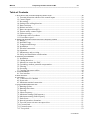
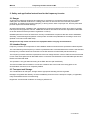
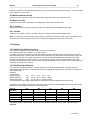
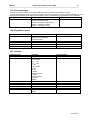
Terminal-connection
1 Phase
bn
B
bk
1
+10V reference voltage
2
Analog preset value input
3
GND (Analog)
4
5
+15V (max. 100mA)
6
Start clockwise (right)
7
8
9
10
bl
ATTENTION!
Please read this manual carefully and
completely. Start with the installation and
the commissioning up afterwards.
Release/Reset
- for condensation-and enthalpy rotor there must be a
connection between terminal 5/9. For lack of space
connected at clamp 10 (see sketch below)
- for sorption rotor there is no connection between
terminal 5/9 allowed
11
12
13
14
15
PTC- motor temperature control
16
PTC- motor temperature control
15/16 connection only when 60W Motor in use
otherwise connect the motor cables
17
18
Connector for
failure signal contact
19
L1
Net
N
Net
PE
PE
BR Braking resistor
BR Braking resistor
U
Motor
V
Motor
W
Motor
PE
PE
21.10.2013
Manual
Frequency Inverter Vector 54 WT
- 38
__________________________________________________________________________________
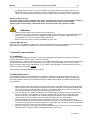
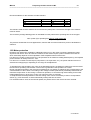
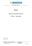
1. Short form of the connection diagram version Hoval
1.1 Terminal allocation scheme of the control inputs
The digital inputs (terminals 6,7,8, 9) are suitable for a control voltage range of 12 – 30V!
The relay 1 (terminals 12, 13, 14) may cope with max. 30VDC/0.6A, 125VAC/0.3A!
The relay 2 (terminals 17, 18, 19) may cope with max. 250V AC/0.7A!
R54/370 (Type 370-WT VECTOR IP54)
R54/750 (Type 750-WT VECTOR IP54)
10k Ohm
B
ϑ
1
+10V reference voltage
2
Analo preset value input
3
GND (Analog)
4
Analog output
5
+15V (max. 100mA)
6
Start-clockwise
7
External sensor
8
Pre-rank speed
9
Parameterset-Changing
10
Release
11
GND (Digital)
12
Relay output 1(No.contact)
13
Relay output 1(Com.Contact)
14
Relay output 1(NC Contact)
15
PTC- Motor temperature-control
16
PTC- Motor temperature-control
17
Relay output (NO contact)
18
Relay output (Com.contact)
19
Relay output (NC -Contact)
Attention: All Motor- and control cables connected to the frequency inverter
(apart from sensor for the rotation-control) have to be screened.
21.10.2013
Manual
Frequency Inverter Vector 54 WT
- 39
__________________________________________________________________________________
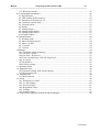
1.2 Control Signal
+
-
The control signal is to be connected at the pin
2
3
The controller is set with a control signal of square 0-10Volt
Other control signals are to be changed with a DIP-Switch
Attention: Do not lay the cable of the control signal parallel to the motor cable!
1.3 Rev setting
5
9
The rev has to be set depending on the rotor type.
Type A/E: (Parameter
Condensation
setrotor/
2) Enthalpie rotor, 10 U/min , you have to build-in a link between
terminals 5 and 9
Type S:
Sorption rotor,
(Parameterset 1)
18 U/min , no link between terminals 5 and 9
1.4 Setting of the rolling direction
If possible, the drive-belt should lead over the pulley coming from above.
The direction of rotation has as a matter of priority to be taken into account at rotation heat exchangers with
washing zone. An arrow then indicates this.
Exchanging two engine phases may change the direction of rotation.
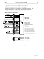
1.5 Rotor start/stop
The rotor is started via terminal 6. The switch has to be included building sided and is controlled via the
building automation control.
Start:
5
6
1.6 Release and reset
The frequency changer is released by allocation of the clamp 10. A connected terminal 10 is prerequisite that
the rotor starts.
Likewise occurring disturbances are acknowledged with a short-time removal of the voltage at terminal 10.
The switch has to be included building sided and is controlled via the building automation control.
5
10
21.10.2013
Manual
Frequency Inverter Vector 54 WT
- 40
__________________________________________________________________________________
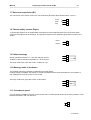
1.7 Rotor run supervision (B1)
The connection of the sensor for the rotor run supervision (B1) takes place at terminals 5, 7 and 11.
brown
black
blue
+
S
-
5
7
11
1.8 Thermo safety contact Engine
To protect the engine from an inadmissible overheating at a low rotational speed, the PTC-thermo safety
contact of the engine must be attached. The guarantee expires at not attached engine safety contact on the
engine.
1.9 Failure message
During operation terminals 17 – 18 of the relay are closed.
At failure or power shut-down terminals 18 - 19 are closed.
black 1
15
black 2
16
17
18
19
The relay contact may cope with a max. of 250V AC, 7A!
1.10 Message state of readiness
The regulator offers the possibility of distributing the ready status.
If mains voltage is available, the frequency inverter released and there aren't disturbances, the regulator is
then operational, terminals 12 and 13 are closed.
The relay contact may cope with a max. of 30V/40mA!
12
13
14
1.11 Precedence speed
If no rule signal is available, the rotor can be turned with a constant speed (40 Hz) for revision purposes. A link
between terminals 5 and 8 is used for it.
5
8
21.10.2013
Manual
Frequency Inverter Vector 54 WT
- 41
__________________________________________________________________________________
2. Safety and application instructions for the frequency-inverter
2.1 Danger
As long as any electrical equipment and machinery is switched on, the operator should not touch voltage
cabling and non-isolated conductors or rotating parts when he removes the covers and the prescribed
protections, in handling the machine improperly, or during service work or improper use, and may well cause
personal injuries and material damage.
All works with transport, installation and commissioning as well as maintenance have to be done by properly
trained personnel (regard IEC 364 res. VENELEC HD 384 or DIN VDE 0100 and IEC report 664 or DIN VDE
0110 and national accident prevention regulations or VGB 4).
Qualified personnel in terms of these basic security considerations are persons that are used to installation,
assembly, commissioning and operation of the product and that have qualifications according to their work
(defined in IEC 364 or DIN VDE 0105).
Always electrically isolate and lock of the equipment before carrying out maintenance
2.2 Intended Usage
Frequency inverters are components for the installation within machines that are operated in industrial plants.
The commissioning of the frequency inverters is prohibited until it is ascertained that the machine that includes
the frequency inverters follows the restrictions of the EU directive 89/ 392/ EWG (machine directive).
The frequency inverters meet the requirements of the low voltage directive 73/ 231/ EWG and the harmonized
norms of the series prEN 50178/ DIN VDE 0160 in connection with EN 60439-1/ DIN VDE 0660 part 500 and
EN 601146/ DIN VDE 0558.
The operation is only permitted according to the EMC directive (89/ 336/ EWG).
The technical data and information to connection conditions are to be found at the rating plate or the
documentation and have to be completely fulfilled.
2.3 Transport and Storage
The considerations for transport, storage and the appropriate handling must be regarded.
Damages recognized after delivery must be immediately announced to the transport company. If applicable,
notify the distributor before commissioning.
Regard the environmental conditions according to prEN 50178.
21.10.2013
Manual
Frequency Inverter Vector 54 WT
- 42
__________________________________________________________________________________
2.4 Installation
Installation and cooling of the devices must be according to the specifications of the concerning
documentation.
The frequency inverters must be secured from improper operational demands. Take care to not bend
electronic devices and/or change isolation distances. Avoid touching electronic elements and contacts.
Frequency inverters contain electrostatic imperiled elements. Improper handling may easily destroy these
elements. Inbuilt electrical components must not be destroyed (health and safety risk in certain
circumstances).
2.5 Electrical connection
At working at current inverters with supplied power regard the valid national accident prevention regulations
(e.g. VGB 4).
The electrical installation has to be done according to the valid directives (e.g. cable diameters, fuse
protection, ground wire connection). More detailed information is to be found in the documentation.
Compliance with the limits for the plant according to the EMC juridical directive is in responsibility of the
manufacturer of the plant. Considerations for the EMC-compatible installation like screening, grounding,
alignment of filters and laying of cables are to be found in the documentation of the frequency inverters.
2.6 Operation
Plants that contain frequency inverters have to be provided, if applicable, with additional observation and
security installations according to the concerning valid security directives, e.g. act on technical work
equipment, accident prevention regulations etc. The documentation of the manufacturer has to be regarded.
After disconnection of the frequency inverters from the supply voltage, voltage conducting device parts and
cable conductors must not be immediately touched because of possibly charged condensers. Please regard
the according notification signs at the frequency inverters. During operation all covers must kept closed.
2.7 Maintenance and servicing
The documentation of the manufacturer has to be regarded.
2.8 Safety and Installation considerations
Frequency inverters from MSF-Vathauer are operating resources for the deployment in industrial high-voltage
plants and are operated with voltages that may cause heavy injuries or death when touching!
• Installations and works may only be executed by qualified electrical trained personnel and at voltage
free device. The user manual has to be available at any time and has to
be consequently regarded.
• The local directives for building electrical plants and accident prevention regulations
must be fulfilled.
The device is up to 5 minutes after disconnecting from the voltage conducted with dangerous voltage.
Due to this, opening of the device or removing the cover res. the I/O
module and the display device is only permitted 5 minutes after disconnecting the device from voltage.
Before turning the mains voltage on all covers must be mounted again.
• Also at motor standstill (e.g. due to electronics lock, short circuit at the output clamps
or blocked drive) the voltage circuit clamps, motor clamps and clamps for the brake resistance may
conduct dangerous voltage. A motor standstill is not identical with
a galvanic disconnection from the mains voltage.
• Attention: The inverter may, depending on the settings, start automatically after powering the mains
voltage.
• The frequency inverter must not be operated without effective ground connection that fulfils the local
directives for high leakage current (>3.5mA).
21.10.2013
Manual
Frequency Inverter Vector 54 WT
- 43
__________________________________________________________________________________
•
At rotating current frequency inverters common FI circuit breakers as single protection are not
applicable when the local directives do not allow a possible direct current component in the error
current. The standard FI circuit breakers have to fulfill the new construction type acc. VDE 0664.
Attention! Danger to Life!
The power supply conducts voltage under certain circumstances for up to 5 minutes after turning off
the mains voltage. Inverter terminals drive cables and drive clamps may conduct voltage!
Touching open or free clamps, cables and device parts may cause heavy injuries or death!
Attention
•
•
•
Children and the public must not have access to the device!
The device may only be used for the purpose intended by the manufacturer. Unauthorized changes
and the use of replacement parts and additional devices that are not sold or approved by the
manufacturer may cause fire, electric shocks and injuries.
Keep the manual in reach and make it available for every user!
European EMC directive
If the F-D vector is installed according to the recommendations of this manual it fulfills the requirements of the
EMC directive according to the EMC product norm for motor driven systems EN 61800-3.
3. Assembly and Installation
3.1 Installation
The devices require adequate ventilation. Here are recommended values above and below the frequency
inverter valid (above >100mm, below >120mm= free area).
Electrical parts (e.g. cable trench, contactor etc.) may be built within these limits. These objects recommend a
minimum distance from the inverter depending on the height. This minimum distance is 2/3 of the object
height. (Example: cable trench height 60mm
2/3 * 60mm= 40mm distance). The build-in direction of the
frequency inverter is principally vertical.
The hot air has to be dissipated above the inverter!
3.2 Cabling directives
The frequency inverters are developed for the operation in industrial environments where high values of
electromagnetic interferences are expected. In general, a professional installation ensures a riskless and
error-free operation. If limits are required that exceed the EMC directive limits, the following directives are
recommended.
1. Please make sure that all devices in the control cabinet are connected together at a shared earthing
point or rail with short cores and great diameter are properly grounded. It is especially important that
every control device connected to the inverters (e.g. automation devices) is connected via a short
core with high diameter at the same grounding point like the inverter.
2. The PE conductor of the drive controlled by the inverter should preferably directly connected to the
ground connection connected with the heat sink together with the PE of the power supply of the
concerning inverter. The existence of a central grounding rail within the control cabinet and the
connection of all ground cables to this rail normally guarantee an error-free operation.
3. As far as possible you should use screened cables for the control. The cable ends have to be
terminated carefully and it must be taken care that the cores are not unscreened over long distances.
The screen of analog set point cables should only be grounded at the frequency inverter single-sided.
Not used cores of the control cores should be grounded.
4. The control cores have to be laid in the most possible distance from the load cores using separated
cable trenches etc. Cable crosses should possibly get an ankle of 90°.
21.10.2013
Manual
Frequency Inverter Vector 54 WT
- 44
__________________________________________________________________________________
5. Make sure that contactors and relays in the control cabinets are suppressed either by RC connection
or varistors in case of ac contactors or by „ free wheeling diodes“ at dc contactors, where the dejam
devices have to be connected at the contactor coil. The dejamming is especially important when
the contactors are controlled by the relays in the inverter.
6. Use screened cores for the load connections and ground the screening at both ends, if possible
directly at the PE output of the inverter.
7. If the drive should run within an environment sensible to electro-magnetic interference, the usage of
interference filters is recommended to reduce the grid-bound and radiated interferences of the
inverter. In this case install the filter as near as possible to the inverter and take care for grounding.
8. Choose the lowest possible switching frequency. This minimizes the intensity of the electro-magnetic
interference created by the frequency inverter.
At installation of the inverters you must not disregard safety directives!
3.3 Measures to secure the EMC
The following measures are to secure the EMC, which are of absolute necessity to the inverter technology.
The inverter fulfills the demands of the high noise immunity and the slight-noise emissions for the usage in
industries, under the guidelines of this manuals installation consideration.
3.4 Grounding, earthen, potential compensation
The correct professional grounding or earthen guarantees the protection of the staff against dangerous touch
voltages (input, output and intermediate circuit voltage). Parasitic currant inductance and low-impedance
potential compensation are important measures to reduce electromagnetic influences.
3.5 Filtering
Filters are inserted into the lead-bound transfer way between the source of interference and the interference
suppressor, which is to reduce lead-bound transmissions and to increase the noise immunity.
This is why, mains-filter and output chokes have been integrated into the FD Vector, and have, in fact,
reached the EMC conformity. Additional, external filter may have a negative effect on the noise emission.
3.6 Screening
Screening is used for decoupling fields between two spatially separate areas, i.e. is also used to decrease the
emission of electromagnetic radiation and to increase the noise immunity. The consistent use of metal cases
is one of the most important standard measures to safeguard the EMC.
3.7 Coupling into motor cables
The use of twisted core cables can essentially reduce inductive couplings into a circuit. Capacitive, inductive
and electromagnetic interferences must be reduced by cable screens. It is important to note that to reduce low
frequency capacitive interference, it is often sufficient to place a one sided screening, whereas inductive and
high frequency electromagnetic interference can only be prevented by screening both sides of the cable.
The screening must not be used as a protection earthen!!!
4. Technical features
The Vector is a frequency-inverter with a modulated attachment, which in its basic offers excellent market
value for goods by using simple applications. With extra integrated modules it can be alternated for a
controlled drive with vector-control or upgraded to a positioning type.
Higher torque in the lower performance area, lower temperature development as well as extended technical
improvements for the user are only a part of the technical features. Protection against under- and overload,
short circuit as well as the voltage system inverters are additional features.
The centre piece is a 16-bit signal processor with an internal flash for the renewal of the pulse and controltechnique-duties.
Voltage system inverter for heat exchangers with sensor less drive-belt rips recognition.
21.10.2013
Manual
Frequency Inverter Vector 54 WT
- 45
__________________________________________________________________________________
At the predecessor model at least one to approx. 8 attenuators had to be distributed over the perimeter of the
warmth wheel to state the running of the wheel by means of the procedures of the attenuators and inductive
givers. When attaching the attenuators the right distance to the inductive giver had to be respected, what was
often difficult because of a slight height blow of some wheels.
At the Vector the wheel is tested in periodical distances sensor less on drive-belt rip by means of a special
procedure.
The test interrupts the predefined run of the wheel in the following way:
1.) Low run at the low seat pan adjusted in the current parameter sentence.
2.) Test on drive-belt rip (as a rule, the wheel stops)
3.) High run at the high seat pan adjusted in the current parameter sentence to approx. 60 Hz
4.) Low run at the low seat pan adjusted in the current parameter sentence
5.) Further operation of the normal mode
However, the VECTOR still offers the possibility of supervising the rotor run with an external sensor.
The practical design offers the following advantages:
Different installation positions optimize the installation, and minimize the space requirement
in the switch cabinet
Integrated braking chopper
A plug-on type operator interface for different installation positions offers the following
advantages:
3-line LC-display
plain text display
on-line parameterization
High operational safety due to:
aluminum cases and standard input/output filters provide high noise immunity and only
slight-noise emissions
short-circuit protection (conditional)
set value input isolated from potential
the new CCDS-SYSTEM (current-control dynamic scan) prevents the inverter from switching-off at short
time excess current flow (e.g. dynamic acceleration)
4.1 User interface
The Vector is available with integrated and pluggable user interface.
At the devices without integrated user interface this is available as an option.
For plug-in you open the great M40-screw joint at the upper lid. Beneath there is a RS232 socket for the PC
connection and a 10-pin contact strip for the user interface. Put the plug of the user interfaces on the pin
contact strip, so that the nose of the plug points up to the D-type socket.
For changes of certain parameters you select the desired parameter as shown in the menu structure. The
value can be changed by pushing the OK key and using the up/down keys. Storing is made by the OK key
once more.
21.10.2013
Manual
Frequency Inverter Vector 54 WT
- 46
__________________________________________________________________________________
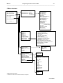
5. Menu structure
Parametersets
Parameterframe 1 -Sorption
In-and Outputs
Parameterframe 2 - Enthalply
Condensation
Run up time R
Run down time R
Run upt time L
Run down time L
Quickstop
Motor nominal frequency
Max. frequency R
Intervall frequency R
Min. frequency L
Max. frequency L
Priority frequency
Static boost
Interval point
Standstill From 1.0 to 0.0
(or pause motor)
DC-brake
Duration DC-brake
Max. current
Pan truncation
Controller value
Settings
Operating values
------------End ---------
Digital In 1
Digital In 2
Digital In 3
Digital In 4
Analog Out
Analog Out Offset
Analog Out Factor
Relay Output 1
Relay Output 2
0) General fault
1) Rotor-run 2 (at circuit)
2) Blocking wheel (at circuit)
3) Overcurrent
4) Set value = actual value
5) Rotary field right
6) Multifunctional (frequency)
7) Temperature too high (inverter)
8) FU ready
9) Motor turns (rotation control)
10) PTC- temperature too high (motor)
11) Multifunction (current) incl. Current limit
12) Parameterset 1 or 2 active
13) DC-brake active
Working modus
Rated outp. Current***
Cos ϕ
*
P- share
*
I- share
*
Switching frequency
Set value
Set value offset
Set value hysteresis
Fade out frequency
Ranges fade out frequency
I²t current
Operation
Factory setting
V/F = linear
V/F = square
Vector
2/4/8/16 kHz
0- 10V
0-10V square – standard value
+10 - -10V
-10 - + 10V
2- 10V
10- 2V square
5- 10V
10- 5V
0- 20mA
0-20mA square
4- 20mA
4-20mA square
Serial interface
Display
Inputs
Display
* Relevant for vector control
*** Relevant for vector control and drive-belt rip recognition
21.10.2013
Manual
Frequency Inverter Vector 54 WT
- 47
__________________________________________________________________________________
Parametersets
Set value
Actual value
Temperature
Current
ZK- Voltage
Software version inverter
Software version display
In-and Outputs
Controller value
Settings
Operating values
------------End ---------
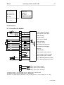
6. Connection
6.1. Connection I/O- Module
10k Ohm
B
ϑ
1
+10V reference voltage
2
Analo preset value input
3
GND (Analog)
4
Analog output
5
+15V (max. 100mA)
6
Start-clockwise
7
External sensor
8
Min.rotating field-frequency
9
Parameterset-Changing
10
Release
11
GND (Digital)
12
Relay output 1(No.contact)
13
Relay output 1(Com.Contact)
14
Relay output 1(NC Contact)
15
PTC- Motortemperature-control
16
PTC- Motortemperature-control
17
Relay output (NO contact)
18
Relay output (Com.contact)
19
Relay output (NC -Contact)
The Relay-contact 1 can be loaded at max. 30VDC/0,6A, 125VAC/0,3A!
The Relay-contact 2 can be loaded at max. 250VAC/7A!
Attention: The digital-inputs (terminals 6,7,8,9) are designed for a control voltage of 12 – 30V!
21.10.2013
Manual
Frequency Inverter Vector 54 WT
- 48
__________________________________________________________________________________
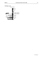
6.2 Power unit
Single phase
Net
L1 Netz
Net
N Netz
PE
PE PE
Braking resistor
BR Bremswiderstand
Braking resistor
BR Bremswiderstand
U
Motor
Motor
V
Motor
Motor
W Motor
Motor
PE PE
PE
21.10.2013
Manual
Frequency Inverter Vector 54 WT
- 49
__________________________________________________________________________________
6.3 Minimum terminal-connection
Single phase
1
+10V
Referenzspannung
+10V
reference voltage
2
analoger
Analog Sollwerteingang
preset value input
3
GND
(Analog)
GND
(Analog)
4
5
+15V
(max
100mA)
+15V
(max.
100mA)
6
StartStartRechtslauf
clockwise (right)
7
8
9
10
Release
Freigabe
11
12
13
14
PTC.motortemperature control
PTC-motortemperature-control
15
PTC- Motortemperaturüberwachung
16 PTC- Motortemperaturüberwachung
Net
L1 Netz
N
Net
Netz
PE PE
PE
Braking resistor
BR Bremswiderstand
BR Bremswiderstand
Braking resistor
U
Motor
Motor
V
Motor
Motor
W Motor
Motor
PE PE
PE
The above drawing shows the min. required terminal-connection of the digital inputs.
7. Programmable parameter sets
Two independent parametersets are available for the parameterization, in which the running-up,- running
down-time as well as the min.-and max. rotating field –frequency for the right- and left rotation can be adjusted
separately.
General note: Left rotation isn't provided at this model. Rotation change is carried out via mixing up
the engine phases instead!
7.1 Running-up time
The high run of the wheel by means of an even acceleration is accounted as the ramp. A prolongation of the
ramp is made by the reduction of the ramp steepness. A shortening is made by the rise of the ramp steepness
Hz
( /s - high Hz value - short ramp, low Hz value - long ramp). At a short ramp, the final torque of the wheel is
reached faster.
21.10.2013
Manual
Frequency Inverter Vector 54 WT
- 50
__________________________________________________________________________________
The quotient: maximum frequency/running-up time yields the so-called ramp. This designates the change of
the rotating field frequency change per time unit. A ´steep’ ramp is equivalent to a short running-up time. A’
flat’ ramp is equivalent to a long running-up time.
The set running-up times must always be application-specific, taking into account the physical realities
resulting there from . Especially short running-up times can influence the motor stability or cause a switch-off
of the inverter due to an excess current. A sensible feeling is also required in the selection of sufficiently long
running-up times for large centrifugal masses.
The running-up times are separately adjustable for clockwise turnings.
7.2 Running-down time
The low run of the wheel by means of an even deceleration is accounted as the ramp. A prolongation of the
ramp is made by the reduction of the ramp steepness. A shortening is made by the rise of the ramp steepness
Hz
( /s - high Hz value - short ramp, low Hz value - long ramp). At a short ramp, the standstill of the wheel is
reached faster.
Essentially, the explanations given in the section “Running-up times” also apply here.
When inappropriate short running-down ramps are selected (especially with large centrifugal
masses) overvoltage in the intermediate circuit can cause a switch-off of the inverter. Since in this state of
operation, the rotating field frequency applied to the motor is slightly less than the frequency of the motor
shaft, energy will be fed back (generator operation) resulting in an inadmissible increase of the intermediate
circuit voltage in the inverter.
If the special application does not admit longer running-down times, use a braking chopper to reduce the
excessive intermediate circuit voltage.
The braking chopper will convert the energy produced in the generator operation into heat losses.
The running-down times are separately adjustable for clockwise turnings.
7.3 Fast stop
The low run of the wheel by means of an even deceleration is accounted as the ramp. A prolongation of the
ramp is made by the reduction of the ramp steepness. A shortening is made by the rise of the ramp steepness
Hz
( /s - high Hz value - short ramp, low Hz value - long ramp). At a short ramp, the standstill of the wheel is
reached faster.
7.4. Motor frequency
Input of the frequency in Hz of the connected motor. See Ident-notice of the motor
7.5 Minimum rotating field frequency
The minimum rotating field frequency to be set in advance below which the inverter should not
drop even if the lowest set value is applied to the analog input. The minimum rotating field frequency is
separately adjustable for clockwise turnings.
Attention:
Only a pre-setting of a min. frequency of 0 Hz will result in a frequency of 0 Hz with an applied
set value of 0 volt. With a set frequency above 0 Hz, a frequency of 0 Hz can only be obtained
via a STOP.
7.6 Maximum rotating field frequency
The maximum rotating field frequency to be set in advance which the inverter should never exceed even if the
highest possible set value (admissible range: 0 V to 10 V) is applied to the analog input. The maximum
rotating field frequency is separately adjustable for clockwise and counterclockwise turnings.
21.10.2013
Manual
Frequency Inverter Vector 54 WT
- 51
__________________________________________________________________________________
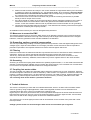
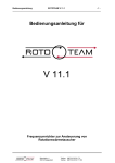
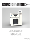
7.7 Static boost
Deviating from the linear V/f characteristics, this voltage increase is specified in percent of the
nominal voltage to increase the starting torque at low rotating field frequencies.
With low rotations, the copper resistance of the stator winding strongly influences the operating
characteristics of the motor. Without a voltage correction, the breakdown torque is significantly reduced
towards low rotating field frequencies. During slow starts, it could happen that the motor does not start due a
too high breakaway torque to be obtained. By using a voltage increase - the so-called BOOST - the starting
torque is increased. The amount of the BOOST is specified in percentage of the nominal voltage at 0 Hz.
Starting at this value, the voltage is continually raised with an increasing frequency and thus approaches the
normal (linear) V/f characteristic: V/f = const. A constantly available voltage increase is called ´static BOOST´.
The range of the voltage increase extends to about a frequency of up to of 2/3 of the kink frequency. To
prevent a torque jump during the transition of the BOOST to the V/f=constant characteristics, all
characteristics of the static BOOST end at the V/f characteristic. Good starting torques are achieved with a
BOOST setting of 8%. Exaggerated high values result in an increased motor temperature which may destroy
in the destruction of the motor by overheat, particularly if no separate fan is used. a high BOOST value can
also cause an excessive currant, which will likewise switch the inverter off.
Figure 6.7.1 Standardized output voltage as a function of frequency and boost
7.8 Interval operation, downtime
If the set point drops below the value set under ‘interval point’ in the menu parameter set 1/2, the interval
operation starts. This means periodical running for approx. 8 seconds with the rotating field frequency
adjusted under interval frequency alternately with the downtime adjusted in the same menu A downtime of ‘0’
causes deactivation of the interval operation.
A downtime of ‘0’ causes deactivation of the interval operation
7.9 Test with sensor on rotor run supervision
In the corresponding parameter set, the parameter “external sensor” has to be set to ‘1’. The tripping time is
dependent on the rotational speed of the rotor. At a high rotational speed, the triggering is faster than at a low
rotational speed. I.e. At registration of an impulse triggered by an attenuator of the inductive giver a time
dependent on the rotating field frequency available at this moment passes, after which a renewed impulse
must be entered to not let go the voltage system inverter in malfunction. The time is graded in 10Hz steps.
E.g. at a rotating field frequency above 100Hz, the time amounts 2 min., with lower than 10Hz it is 20 min. At
rotational speed of '0', the internal time triggering is interrupted to prevent the system shutdown at
specification of extremely long downtimes and only very short running times.
7.10 Current limit
At exceeding of the current limit set in the particular parameter sets the rotary field frequency is reduced to a
value where the motor current is within the set current limit. The reduction may happen to a rotary field
frequency of up to app. 8Hz.
21.10.2013
Manual
Frequency Inverter Vector 54 WT
- 52
__________________________________________________________________________________
7.11 External sensor
If the rotor blockade res. the drive-belt rip recognition should not happen sensor less, you have to connect a
sensor, which is activated in the LCD, to the according digital input.
7.12 Test period
The interval for the drive-belt test can be adjusted parameter sentence depending in the menu item 'test
period' in steps from 0.1 days up to 25 days. The setting '0.0 days' means: no tests take place!
Prerequisite for a faultless test is the setting of the 'engine nominal current' (to take from the engine type
signpost) in the menu 'regulator values'.
A considerably too low setting of the engine nominal current tends to no rip recognition.
The test is carried out at assigned release independently of the present operating state in periodical intervals
and interrupts this for a short time.
The first test is carried out at assigned release at power on within one minute. If drive-belt rip is determined,
the engine is stopped and an error message (rotor standstill) is carried out. The error message can be moved
back by a short-time removal of the release [10] or by disconnection of the voltage system inverter of the net.
7.13. Blocking current
Test on wheel blocking
The test on drive-belt rip a test on blocking of the wheel follows. To this end the motor is operated with a
rotating field frequency of 60Hz and after reaching it the phase current is checked.
If this is greater or equal to that entered in the chosen parameter set under 'blocking current', the motor is
stopped and the error message ('wheel blockage') is carried out.
Attention!!!
Beforehand, it is absolutely is absolutely essential to detect the current consumption of the motor at 60 Hz at
a.) normal operating conditions and b.) wheel blockage, to e.g. determine the mean average value from both
as the shout-down current, which is entered under 'blocking current'!
Note: If the motor comes to a halt as the same time as the wheel blocking, a considerably larger current
difference, which fundamentally makes the setting process easier, will be the result.
Important notes: Within a minute after the power-on -if appropriately parameterized- the first test is
carried out regarding drive-belt rip and rotor blockade. Wrongly entered parameters which inevitably
permanently lead to an error message (particular wrong height of the blocking flow 'for the determination of
the rotor blockage and false setting of the nominal current' for the determination of the V-crack '), it is
recommended to carry out all settings without release (0 volts at terminal 10) undisturbed.
An error message is reset by removing the release. Pressing the button 'up pointing arrow' moves the LC
display back at taken release so that the error message disappears. After setting the release, the test is
repeated within one minute, so that in the presence the events can be tracked.
8. In- and Outputs (I/O-Module)
8.1 Digital Inputs
The pins 6,7,8 and 9 are digital inputs and are assigned with the following functions
Clockwise start (right)
Counter clockwise start (left)
Minimum rotating field frequency fmin
Parameterset changeover 1-2
8.2. Min rotating field frequency
At high level at input -8- and present release, independently of the function start right, the rotating field
frequency parameterized under ‘pre-rank frequency’ in the parameter set 1 res. 2 is laid.
21.10.2013
Manual
Frequency Inverter Vector 54 WT
- 53
__________________________________________________________________________________
8.3 Parameter set changeover 1-2
The current parameter set is chosen through the digital inputs. A parameter set wanted by wiring the
corresponding inputs is taken over online.
8.4 Clockwise rotation start
If this function is activated, it will cause the motor to run up to speed at the set running-up time specified in the
selected parameter set until the set value is reached and in the specified direction. Deactivation at an inactive
Start will cause a run-down at the set ramp of the selected parameter set down to a standstill. If the ramp of
the corresponding parameter set is deactivated, the shaft is immediately released.
8.5. External sensor
Connection of an external sensor if wheel blockade res. drive-belt rip recognition should not happen sensor
less.
8.6 Release
Activating this input -10- initializes the control and the power circuit of the inverter to make it ready to operate
state. The opening of the input immediately releases fast-stop function, whose running-down time is set in the
parametersets.
8.7 Analog Output
The analog output can be connected with different functions like e.g. the rotary field frequency in 1/10 Hz
(address 38). The complete list of analog output functions is to be found in the appendix.
8.8 Analog Output Offset
This function allows you to shift the output voltage of the analog output from the zero point.
8.9 Analog Output Factor
This function spreads the output voltage for a configurable factor.
8.10 Digital Output
The relay output 1 and 2 can be set with the following functions:
0) Sum error message
1) Rotor standstill
2) Wheel blockade
3) Overcurrent
4) Set point = effective value
5) Rotary field right direction
6) Multi-function (frequency)
7) Overtemperature inverter
8) FU ready for operation
9) Motor turning (zero observation)
10) PTC overtemperature (Motor)
11) Multi-function (current) incl. current limit
12) Parameter set 1 or 2 active
13) Direct current brake active
Note: It has to be taken into account that at the drive-belt rip test the rotating field frequency is varied and
therefore also the exits react correspondingly: Multifunction, analog output, set point = actual value, engine
turns!!!
9. Controller values
9.1 Working mode
A selection can be made between the linear V/f characteristic (with the output voltage proportional to the
rotating field frequency) and the square characteristic (“fan characteristic" with a squared output voltage
21.10.2013
Manual
Frequency Inverter Vector 54 WT
- 54
__________________________________________________________________________________
increase in relation to the rotating field frequency). The reference point is the kink frequency. As a third option
is the usage for Vector-control
9.2 Motor-nominal-current
Input of the motor-nominal-current according to the rating plate of the connected DC-motor
9.3 Motor Cos Phi
Input of the power factor according to the rating plate of the connected DC-motor
9.4 P section
Setting of the P section of the PI controller, which only affects the VECTORCONTROLLING
9.5 I section
Setting of the I section of the PI controller, which only affects the VECTORCONTROLLING
Note: To ensure the correct function of the frequency inverters, the motor nominal current, the G/ratio Cos ϕ
and the motor nominal frequency must be according to the rating plate of the connected motor!
10 Settings
10.1 Switching (clock) frequency
The frequency, be which the inverter of the power circuit is switched.
The following values are possible: 2, 4, 8, and 16 kHz.
Annotation: With the exception of 16 kHz, the switching (clock) frequency will be noticed as a more or less
loud secondary noise. The lower the switching (clock) frequency, the lower the switching power losses in the
power circuit, the less the inverter will warm up. The best motor characteristics are achieved from 2 kHz
upwards. The switching (clock) frequency of 16 kHz should only be used in exceptional cases due to the
increased heating of the inverter. If this is used a sufficient ventilation of the inverter must be guaranteed and
the power may have to be reduced.
10.2 Set Point Specification
In the menu ‚set point specification’ a square reference can be produced between an analog set point
specification with reference to f-max and the resulting rotating field frequency with the choice of a square set
point specification.
Example:
f-max=100Hz
Analog set point:
0V
2,5 V 5,0 V 7,5 V 10 V
Set point (linear):
0 Hz 25 Hz 50 Hz 75 Hz 100Hz
Set point (square):
0 Hz 6,2 Hz 25 Hz 56,2Hz 100 Hz
The actual value of the rotating field frequency follows the set point regarding the current ramp.
Regardless of the setting of the preset value in the menu structure a setting must also be done with the DIPswitch on the I/O-module according to the following table.
Type of
Set value
0...10V
-10...+10V
0...20mA
4...20mA
0-100kHz
S1
S2
S3
S4
S5
On
Off
On
On
Off
Off
On
Off
Off
Off
Off
Off
On
On
Off
On
On
On
On
Off
Off
Off
Off
Off
On
The preset value of the inverter must be wired regardless of which preset value specifications is
selected.
21.10.2013
Manual
Frequency Inverter Vector 54 WT
- 55
__________________________________________________________________________________
10.3 Set value - Offset
Offset Specification (e.g. to compensate for parasitic noise).
Figures in the following two diagrams show how the original characteristic is influenced by a positive or
negative offset.
The setting of the set value offset follows in steps of 0.1 Hz.
10.4 Set value - Hysteresis
The set hysteresis value is used to stabilize the specified rotating field frequency.
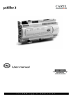
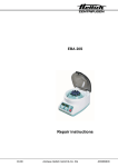
10.5 Fade out frequency1, fade out frequency2
To suppress resonance effects in drive systems, a frequency range can be defined in which no
stationary operation will be possible. The definition of a frequency range is made by means of
programming a fade-out frequency ±2 Hz. A reference value specification within this range causes an offset of
the actual value (refer to figure 9.5.1) above or below the limit frequencies.
21.10.2013
Manual
Frequency Inverter Vector 54 WT
- 56
__________________________________________________________________________________
Figure 10.5.1 Rotating field frequency by use of the fade out frequencies
10.6 I²t current
The I²t function is used to avoid a thermal overload of the motor, and/or to avoid a motor operation over an
extended period of time in an unintended operating status (e.g. shaft blocking). For this purpose, the current
value must remain above the normal operating status. A long period of time must be entered accordingly to
avoid a shutdown of the inverter caused by short current peaks.
10.7 Regulation
This menu item regulates the setting if the frequency inverter runs through the I/O-module or the display
10.8 Factory settings
The factory setting is activated by the display and causes an overwriting of every parameter with the preset
factory values.
11. Operating values
The "Operating values" menu item enables an operation status request with regard to the following visible
messages:
12. Application notes
12.1 Dynamic braking with a brake chopper
The built-in brake chopper equipped with an external braking resistor enables dynamic braking of large
masses and does not initiate a switch-off of the inverter.
When braking a centrifugal mass at a relatively short running-down time (brake time), the mass inertia of the
entire drive works as a generator torque.
This braking operating is equivalent to an energy feedback of the drive resulting in a temporary circuit voltage
increase up to the point where the excessive voltage switch-off is initiated.
By routing this brake energy into a resistor, the switching off can be prevented.
The brake chopper compares the temporary circuit voltage with a reference voltage which has a voltage level
below the over-voltage tripping level. When the reference voltage is exceeded a power transistor connects the
braking resistor to the temporary circuit voltage. The resistor then converts the power generated by the motor
into a heat loss.
The brake power can be calculated as a function of the activation time (ED) of the braking resistors.
Thus the brake chopper can be individually adapted to the drive.
If a brake resistor is used for braking, the braking energy is usually dissipated equally via the master and the
slave (no coupling).
21.10.2013
Manual
Frequency Inverter Vector 54 WT
- 57
__________________________________________________________________________________
Recommendations for the selection of brake resistors
Vector
370
550
750
Resistor
100Ω
100Ω
100Ω
Peak power
1kW
1kW
1kW
Imax
2,5A
2,5A
2,5A
The resistors used must be suited to the current and the peak power. The electric strength of the resistors
must be 1000V.
The necessary average braking power is calculated from the peak and the operating time of the chopper.
Nom. power (W)= operating-time ED (s) * peak power (W)
Cycle time (s)
The practice showed that for most applications, resistors with a nominal continuous power of 60 Watts are
sufficient.
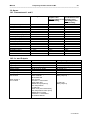
12.2 Motor protection
Despite a high-grade sine modulation, additional losses occur in the motor in powering standard 3-phase
asynchronous motors. Even at nominal revolutions, these losses require a power reduction the extent on
which essentially depends on the exploitation of the temperature limits of the motor.
For drives of a square counter-torque (e.g. fans) and 50 Hz as maximum rotating field frequency, the imposed
power reduction is usually around 0 - 10%.
For drives of a constant counter-torque (compressors, conveyer belts, etc.), the power reduction has to be
selected accordingly larger, depending on the range of the adjustment.
To guarantee the safe operation of a motor in the adjustment range, the stationary load torque must lie below
the continuous operating characteristic of the motor to guarantee a safe operation of a motor.
During operation and starting, the drive will momentarily be in a position to submit torque corresponding to the
current limitation of the inverter. The setting of the voltage increase (static Boost) essentially determines the
maximum torque below 10 Hz. During a continuous operation, an excessive high boost setting for the lower
rotating field frequency range (up to 15 Hz) can cause the motor to overheat.
A comprehensive thermal protection of the self-cooling motor can be achieved by means of a temperature
sensor (e.g. PTC thermistor or thermal time-delay switch) built into the motor.
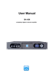
For revolutions above 120% of the nominal speed, the performance of the motor has to be checked.
21.10.2013
Manual
Frequency Inverter Vector 54 WT
- 58
__________________________________________________________________________________
Bild 12.2.1 Operating characteristics of a frequency-controlled asynchronous
machine
13. Technical data
Type
Output
motor side
Input
Mains side
General
Data
Output power of
apparatus
Max. motor power
Rated output current
Max. output voltage
Output frequency
Output choke
Input voltage
Mains filter
Mains frequency
Fusing
(no motor
protection)
Protection class
Ambient
temperature
Ambient humidity
Vector 370/2-1-54-G1WT
KVA 0,85
Vector 750/2-1-54-G1WT
KVA 1,6
0,37 kW
2,2A
3 x 230 V
0 – 400 Hz
Internal
230V±15%
Internal
50 / 60 Hz
6AT
0,75 kW
4,0 A
0 – 540 Hz
Internal
230V ± 15%
Internal
50 / 60 Hz
8AT
IP 54
0 – 40 °C
IP 54
0 – 40 °C
20 – 90 % rel. Not
dewing
20 – 90 % rel. Not
dewing
Power loss
Ca. W 35
Ca. 45 W
Power reduction at 16 kHz: Installation height above 3000m 1% per 100m
21.10.2013
Manual
Frequency Inverter Vector 54 WT
- 59
__________________________________________________________________________________
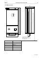
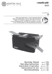
13.1 Measurements
C
B
F
D
1
0
A
E
keep at least 100mm
distance to cable duct res.
for cable route
Measurements
FD Vector 54
A
65 mm
B
270 mm
C
282 mm
D
90 mm
E
112 mm
F
5 mm
21.10.2013
Manual
Frequency Inverter Vector 54 WT
- 60
__________________________________________________________________________________
14. Annex
14.1. Parameterset 1 and 2
Characteristics
Value range
Run.-up time right
Run-down time right
Run-up time left
Run-down time left
Faststop
Motor nominal frequency
Interval frequency right
Max. frequency right
Interval frequency left
Max. frequency left
Priority frequency
Static boost
Interval point
Standstill
Test period
Blockade Current
Current Limit
External Sensor
0,1 – 1000 Hz/s
0,1 – 1000 Hz/s
0,1 – 1000 Hz/s
0,1 – 1000 Hz/s
0,1 – 1000 Hz/s
0 – 400 Hz
0 – 400 Hz
0 – 400 Hz
0 – 400 Hz
0 – 400 Hz
0 – 400 Hz
0 – 30 %
0 – 30 Hz
0 – 30 Min
0,0 – 25,0 Days
0 – 30 A
0 – 100 A
0, 1
Parameter set 1
Parameter set 2
sorption rotor
Condensation rotor/
without bridge Cl.5-9 Enthalpie rotor
Default setting
with bridge Cl.5-9
Default setting
1,5 Hz /sec
1,5 Hz /sec
1,5 Hz /sec
1,5 Hz /sec
1,5 Hz /sec
1,5 Hz /sec
1,5 Hz /sec
1,5 Hz /sec
1,5 Hz /sec
1,5 Hz /sec
50 Hz.
50 Hz.
7 Hz.
7 Hz.
92,0 Hz.
50,0 Hz.
- 7 Hz.
- 7 Hz.
- 92,0 Hz.
- 50,0 Hz.
40,0 Hz.
40,0 Hz.
18 %
18 %
5 Hz.
5 Hz.
1 min
1 min
0
0
0,8 A
0,8 A
20,0 A
20,0 A
1
1
14.2. In -and Outputs
Characteristics
Digital input 1
Digital input 2
Digital input 3
Digital input 4
Analog output
Analog output Offset
Analog output factor
Digital output 1
Pin 12/13/14
Relay output 2
Pin 17/18/19
Variables
Start right
External Sensor
Minimal frequency
Parameter set changeover 1-2
36,38,40,41,57,58,59
1- 1024 Bit
1- 9999
Sum error message
Rotor standstill
Wheel blockade
Over current
Set value = Actual value
Rotary field right
Multifunction (frequency)
Over temperature
FU stand by
Motor turns (zero observation)
Over temperature motor (PTC)
Multifunction (current)
Parameter 1 / 2 activated
DC-brake activated
Factory settings
Start clockwise (right)
Start counterclockwise (left)
Minimal frequency
Parameter set changeover
38 (Actual rev.)
0000 Bit
1139
Sum error message
(Relay output 2)
FU stand by
(Relay output 1)
21.10.2013
Manual
Frequency Inverter Vector 54 WT
- 61
__________________________________________________________________________________
14.3. Error messages
Occurring errors are shown on the LCD in plain text res. by means of the blinking red LED.
The red LED blinks according to the at this time present error for a certain amount of times followed by a short
break and then starts all over again with the blinking cycle. The following error assignments are available
Label
Value range
red LED
2*blink = Rotor standstill
3*blink = Wheel blockade
4*blink = overtemp. engine (PTC)
5*blink = overtemp. inverter
6*blink = error power device
14.4. Regulation values
Characteristics
Working mode
Motor-nominal-current
Motor Cos. ϕ
P- share PI- controller
I- share PI- controller
Variables
Linear V/f characteristic
Square V/f characteristic
Vectorcontrolling
0- 20A
0,00-1,00
0- 9999
0- 9999
Factory setting
Linear V/f characteristic
1,5A
0,76
10
40
14.5. Settings
Characteristics
Switching (clock) frequency
Set value assignment
Set value offset
Set value hysteresis
Fade out frequency
Field fade out frequency
I²t- current
Operation
Variables
2,4,6,8,16kHz
0- 10V
0-10V square
+10 - -10V
-10 - + 10V
2- 10V
2-10V square
5- 10V
10- 5V
0- 20mA
0-20mA square
4- 20mA
4-20mA square
Interface
Display
0,0- 100Hz
0,0- 100,0
0,0- 400,0Hz
0,0- 200,0Hz
0,0- 30,0A
Inputs
Display
Factory setting
2kHz
0- 10V square
0Hz
0
0Hz
0Hz
20,0A
Inputs
21.10.2013
Manual
Frequency Inverter Vector 54 WT
- 62
__________________________________________________________________________________
14.6. Analog output
The following shows the address and with it the connection to the function of the analog output.
Address
36
38
40
41
57
58
59
Function
Set- speed
Actual- speed
Module temperature
Intermediate circuit voltage
Phase current U
Phase current V
Phase current W
15. Fault list to the frequency inverter for heat exchangers
Message over current (6*flash = Error power device)
Check engine and engine line on short circuit
Check screen on short circuit
Remove engine line at the frequency inverter and check FC LED in FC
Message rotor standstill (2*flash = rotor standstill, 3*blink = wheel blockade)
Check switching distance of the sensor
Check sensor line on cable disruption
Check frequency inverter setting on "sensor supervision"
Watch LED at the sensor, at switching the sensor the LED is on
Message engine temperature too high (4*flash = Excess temperature engine)
Check whether the engine is equipped with a PTC
Check the engine temperature manually (Shut down temperature approximately at 130°C).
Engine cools down after switching off again, error message remains active until the new initialization.
Examine contacts at the frequency inverter
Check cable disruption emergency (if necessary, insert a bridge into the clamp for checking)
Message frequency inverter temperature too high (5*flash = Excess temperature inverter)
Check the inverter temperature manually
FC cools down after switching off again, error message remains active until the new initialization.
Check current consumption of the frequency inverter
Check the static boost (active at low rotating field frequency)
Adjust switching (clock) frequency on 2 kHz.
Check environmental temperature
21.10.2013