1
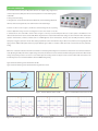
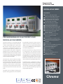
PANEL DESCRIPTION
Load Module
1
Mainframe Controller
8
9
2
3
4
11
12
10
13
14
16
15
17
18
5
6
20
24
25
7
27
19
26
21
22
23
Rear Panel
28
29
30
31
32
33
1
2
3
4
5
6
7
8
9
10
11
12
13
14
15
16
17
LED indicator
SHORT key : To apply a short circuit across the input
STATIC/DYNA key : To select static or dynamic test mode
L/R key : To select left or right channel of input load(63102A, 63107A)
A/B key : To select static A or B load (other models)
V terminal : To measure the UUT's output voltage using remote sense
Rotary knob : To adjust load setting continuously
Load terminal
LCD display
LED indicator : To display the channel at which load is set
CHAN key : To select input load channel
MODE key : To select the operation mode of CC, CR, CV or CP
PROG key : For program data setting
OCP/OPP key : Over current protection/Over power protection testing
RECALL key : To recall the front panel input status from memory
SAVE key : To save the front panel input status into memory
SPEC key : To set up High/Low limits for GO/NG test
CONF key : To set the configuration
18 ON/OFF key : To enable or disable the load input
19 Up/Down key : To select the next or previous display
in edit mode
20 Numeric key : For data setting
21 ENTER key : To confirm editing data on the instrument
22 SHIFT key : As LOCAL key when in remote mode
23 Power switch
24 SHIFT + 0 key : System function
25 SHIFT + . key : Lock function
26 SHIFT + 3 key : Clear the currently edited data
27 Digital I/O : Used for system input/output control signals
28 RS-232C connector
29 GO/NG output port
30 GPIB or USB slot
31 AC input voltage switch
32 AC input fuse
33 AC input connector