1
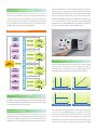
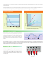
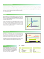
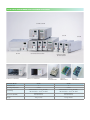
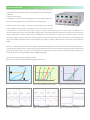
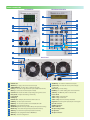
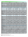
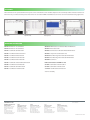
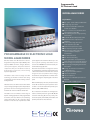
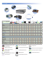
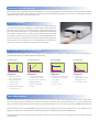
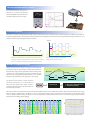
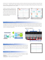
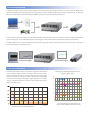
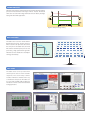
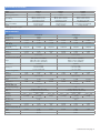
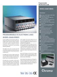
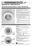
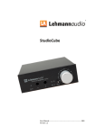
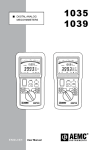
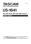
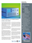
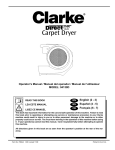
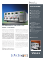
Programmable
DC Electronic Load
MODEL 6310A SERIES
Key Features:
PROGRAMMABLE DC ELECTRONIC LOAD
MODEL 6310A SERIES
The Chroma 6310A series Programmable DC
Electronic Load is ideal for the test and evaluation
of multi-output AC/DC power supplies, DC/
DC converters, chargers and power electronic
components. It is designed for applications in
research and development, production, and
incoming inspection. The system is configured by
plugging the user selectable load modules into
the system mainframe. The user interfaces include
an ergonomically designed user friendly keypad
on the front panel and the following computer
interfaces: RS-232C, USB or GPIB.
The 6310A series offers 12 different modules
with power ratings from 20 watts to 1,200 watts,
current ratings from 0.5mA to 240A, and voltage
ratings from 0.5mV to 600V. The loads can be
operated in constant current, constant voltage,
constant power and constant resistance and may
be placed in parallel for increased current and
power.
programmable parameters include: slew rate,
load level, duration and conducting voltage. In
addition, up to 100 sets of system operating status
can be stored in EEPROM and recalled instantly for
automated testing applications.
Real time measurement of voltage and current
are integrated into each 6310A load module
using a 16-bit precision measurement circuit. The
user can perform on line voltage measurements
and adjustments or simulate short circuit test
using the user friendly keypad on the front panel.
Additionally, the 6310A series offers an optional
remote controller for automated production lines.
The 6310A series has a self-diagnosis routines to
maintain instrument performance. It also provides
OC, OP, OT protection, and alarm indicating OV,
reverse polarity to guarantee quality and reliability
for even in the most demanding engineering
testing and ATE applications.
The 6310A series can simulate a wide range of
dynamic loading applications. The waveforms
USB
GPIB
RS-232C
■ Max Power: 200W, 100W×2(Dual),
30W & 250W, 300W, 350W, 600W, 1200W
■ Wide range 0~600V operating voltage
■ Compatibility between 6310 and 6310A
■ Up to eight channels in one mainframe,
for testing multiple output SMPS
■ Parallel load modules up to 1400W for
high current and power applications
■ Synchronization with multiple loads
■ Flexible CC, CR, CP and CV operation modes
■ Dynamic loading with speeds up to 20kHz
■ Fast response of 0.32mA/µs ~ 10A/µs slew rate
■ Minimum input resistance allows load to
sink high current at low voltage
(63123A : 0.6V@70A)
■ Real time power supply load transient
response simulation and output
measurements
■ User programmable 100 sequences. Front
panel input status for user-friendly operation
■ High/Low limits of testing parameters to
test GO/NG
■ Digital I/O control
■ Over current protection (OCP) testing function
■ 16-bit precision voltage and current
measurement with dual-range
■ Remote sensing capability
■ Short circuit test
■ Self-test at power-on
■ Full Protection: OC, OP, OT protection
and OV, reverse alarm
■ USB, GPIB & RS-232C interfaces
VERSATILE SYSTEM CONFIGURATION
8-channel 100W/channel load with standard front-panel inputs. This
makes it ideal for testing multiple output switching power supplies
C h r o m a 6310A P r o g r a m m a b l e E l e c t r o n i c L o a d i n t e g r a t e s
and multiple DC-DC converters. There are also higher wattage modules
microprocessor capabilities into each load module and mainframe
that may be mixed and matched for an even more versatile system.
to provide simple and accurate parallel operation to optimize the
Additionally, the GO/NG output port is useful for UUT's pass/fail testing
speed and control among multiple load modules. All load modules
on an automated production line. All modules on the 6314A/6312A
may be configured to work synchronously, to test multiple outputs
mainframe share a common GPIB address to synchronize and speed up
simultaneously, thus simulating real life applications.
the control of the load modules and the read-back of data.
6310A System Block Diagram
Series Interface
Series Interface
Series Interface
Series Interface
APPLICATION OF SPECIFIC LOAD SIMULATION
Series Interface
RS232
INTERFACE
The 6310A load modules operate in constant current, constant voltage,
Series Interface
Series Interface
constant power or constant resistance to satisfy a wide range of
test requirements. For example, the test of a battery charger can be
simulated easily by setting the load to operate in constant voltage.
GPIB
INTERFACE
USB
INTERFACE
DIGITAL I/O
CONTROL
V
Series Interface
V
Series Interface
Constant Resistance Mode
Constant Current Mode
V
COMPATIBILITY WITH 6310 SERIES
The 6310A series load modules will be compatible with the 6310 series
mainframes (6312/6314). In addition, the remote control commands will
be compatible between the 6310 and the 6310A series without needing
to re-writing any remote control programs.
MODULE LOAD DESIGN
Th e C h ro m a 6314A 1400W a n d 6312A 700W e l e c t ro n i c l o a d
I
I
V
I
I
Constant Voltage Mode
Constant Power Mode
Each load module is designed with state-of-the-art technology and
connects all the power MOSFET devices in parallel to insure high
accuracy load control with a minimum drift of less than 0.1%+0.1%F.S.
mainframes accept the user-installable 6310A series load modules for
of the current setting. Chroma's use of FET technology provides
easy system configuration and will mount in a 19" instrument rack. The
minimum input resistance and enables the load to sink high current
6314A holds up to four 63102A load modules, which will result in an
even at very low voltages. For example, the model 63123A is capable
of sinking 70A at 0.6V, and well-suited for testing the new 3.3V low voltage power supplies. Low voltage operation, down to zero volts, is possible at
reduced current levels.
The 6310A load module uses a photo coupler for isolation between the output and control sections, thus each load is isolated and floating. The user can
use multiple load modules independently to test multi-output power supplies, or parallel them for high power testing applications.
Low Voltage Characteristics (Typical)
Model 63101A/63102A/63103A/63106A/63112A/63123A
Model 63123A Input Characteristics
240
120
100
200
80
180
70
160
60
140
50
120
63106A
100
40
80
30
63123A
60
20
Current (A)
Voltage (V)
63112A
220
10
2.916
10
20
30
40
50
60
70
Current (A)
63103A
40
63101A
20
63102A
0 0.1 0.2 0.3 0.4 0.5 0.6 0.7 0.8 0.9 1.0 1.1 1.2 1.3
Note: All specifications are measured at load
input terminals. (Ambient Temperature of 25˚C)
Voltage (V)
DYNAMIC LOADING AND CONTROL
Modern electronic devices operate at very high speeds and require
Load 1
fast dynamic operation of their power providing components. To
satisfy these testing applications, the 6310A loads offer high speed,
rise rate
fall rate
programmable dynamic load simulation and control capability. The
Load 2
figure aside shows the programmable parameters of the 6310A
modules:
T1
T2
The programmable slew rate makes the simulation of transient load change demanded by real life applications possible. The 6310A internal waveform
generator is capable of producing a maximum slew rate at 10A/µs, and dynamic cycling up to 20kHz. It's dedicated remote load sense and control circuit
guarantee minimum waveform distortion during continuous load changes.
MULTI-CHANNEL CONTROL
The 6310A comes with RS-232C as standard for remote control and
automated testing applications. The USB and GPIB interfaces are
available as options. In addition, the 6310A provides an efficient
solution for testing single output AC to DC or DC to DC converters by
controlling multiple loads. The 6310A provides the capability to test up
to 8 UUTs at a time.
UUT : Adaptor
POWERFUL MEASUREMENTS
Each 6310A load module has an integrated 16-bit precision A/D converter for voltage measurement with an accuracy of 0.025%+0.015%* of full scale.
The built-in resistive load current sensing circuit is capable of measuring current with an accuracy of 0.04%+0.04%* of full scale. Apart from voltage and
current measurement, 6310A also provides power measurement function and there is no need for users to spend time for power calculation. Also, short
circuit can be simulated. All measurements are done using remote sensing to eliminate any error due to voltage drops along the measurement path. The
user can also select from a complete set of voltage and current measurements.
Note * : Only for Model 63123A
OCP TEST
Modern switching power supplies are designed with over current protection
(OCP) circuitry; therefore, it is important to test the OCP circuitry to make sure it
is functioning within its designed specifications. The 6310A series provides an
Amplitude
V
easy and fast solution for this testing.
UUT Output Voltage
By simply choosing the channel and setting the OCP parameters (start current,
end current, step current and dwell time) from the front panel, the 6310A
series provides a fast and easy OCP testing solution. The 6310A series will
automatically detect the OCP point, making it an ideal solution for design
verification as well as production line testing.
Loading Current
I
▃ Start Current
▃ Dwell Time
Time
▃ Step Current
▃ End Current
TIMING FUNCTION
The 6310A series of loads include a unique timing & measurement function,
which allows precise time measurements in the range of 1ms to 86,400s. This
Final Voltage
feature allows the user to set the final voltage & timeout values for battery
discharge testing, super capacitor discharge, and other similar applications.
Battery Voltage
Loading Current
For example, the figure on the right shows the 6310A internal timer starting at
Load ON, and ending when the battery voltage reaches the final voltage.
Time
Battery Discharge Testing
DIGITAL I/O
The digital I/O interface makes the 6310A DC Load
the ideal choice for automated testing requirements.
Through the digital I/O, the 6310A can accept digital
signals to trigger its functions (Load On/Off, OCP test,
etc.) as well as current output status signals.
Pin
Pin 1
Pin 2
Pin 3
Pin 4
Pin 5
Pin 6
Pin 7
Pin 8
Definition
Reserved
DGND
DGND
DGND
DGND
Load ON/OFF (O/P)
Total Pass (O/P)
Total Fail (O/P)
Pin 9
Pin 10
Pin 11
Pin 12
Pin 13
Pin 14
Pin 15
Short Signal (O/P)
Protection Signal (O/P)
External Load ON/OFF (I/P)
Reserved
Reserved
DGND
External Trig.
For Sequences Run (I/P)
6310A SERIES PROGRAMMABLE DC ELECTRONIC LOAD FAMILY
63106A / 63108A
63101A
63112A
6314A : 4 in 1 Mainframe
Mainframe Model
Number of slots
Operating Temperature
Input Rating
Dimensions (HxWxD)
Weight
63102A / 63107A / 63110A
6312A : 2 in 1 Mainframe
6312A
63105A
63103A / 63123A /
63113A / 63115A
A631001:
Remote Controller
A631000 :
GPIB Interface
A631003 :
USB Interface
6314A
2
4
0~40˚C
0~40˚C
1Ø 100/200Vac ± 10% VLN, 47~63Hz ;
1Ø 115/230Vac ± 10% VLN, 47~63Hz
1Ø 100/200Vac ± 10% VLN, 47~63Hz ;
1Ø 115/230Vac ± 10% VLL, 47~63Hz
194x275x550mm /
7.6x10.8x21.7inch
194x439x550mm /
7.6x17.3x21.7inch
15 kg / 33.1 lbs
21.5 kg / 47.4 lbs
LED LOAD SIMULATOR
As a constant current source, the LED power driver has an output voltage range with a
constant output current. LED power drivers are usually tested in one of the following ways :
1. With LEDs
2. Using resistors for loading
3. Using Electronic Loads in Constant Resistance (CR) mode, or Constant Voltage (CV) mode
However, all these testing methods, each of them has their own disadvantages.
As shown on the V-I curve in Figure 1, the LED has a forward voltage VF and a operating
resistance (Rd). When using a resistor as loading, the V-I curve of the resistor is not able
to simulate the V-I curve of the LED as shown in blue on Figure 1. This may cause the LED power driver to not start up due to the difference in V-I
characteristic between the resistors and the LEDs. When using Electronic Loads, the CR and CV mode settings are set for when the LED is under stable
operation and therefore, is unable to simulate turn on or PWM brightness control characteristics. This may cause the LED power driver to function
improperly or trigger it's protection circuits. These testing requirements can be achieved when using a LEDs as a load; however, issues regarding the LED
aging as well as different LED power drivers may require different types of LEDs or a number of LEDs. This makes it inconvenient for mass production
testing.
Chroma has created the industries first LED Load Simulator for simulating LED loading with our 63110A load model from our 6310A series Electronic
Loads. By setting the LED power driver's output voltage, and current, the Electronic Load can simulate the LED's loading characteristics. The LED's forward
voltage and operating resistance can also be set to further adjust the loading current and ripple current to better simulate LED characteristics. The
63110A design also has increased bandwidth to allow for PWM dimming testing.
Figure 4 shows the dimming current waveform of the LED.
Figure 5 shows the dimming current waveform when using 63110A as a load.
I
I
LED Curve
Io
I
Rd1
Rd3
V
Rd1
Rd4
Io
Rd
Vo
Rd2
Rd3 Rd2
Io
Vo1
Vo2
Vo3
Vo4
V
VF1 VF2 VF3 Vo
V
Figure 1 - LED V-I characteristics
Figure 2 - Simulate different number of LEDs
Figure 3 - Simulate different characteristic of LEDs
Figure 4 - LED dimming test
Figure 5 - 63110A dimming test
Figure 6 - LED driver turn-on waveform
PANEL DESCRIPTION
Load Module
1
Mainframe Controller
8
9
2
3
4
11
12
10
13
14
16
15
17
18
5
6
20
24
25
7
27
19
26
21
22
23
Rear Panel
28
29
30
31
32
33
1
2
3
4
5
6
7
8
9
10
11
12
13
14
15
16
17
LED indicator
SHORT key : To apply a short circuit across the input
STATIC/DYNA key : To select static or dynamic test mode
L/R key : To select left or right channel of input load(63102A, 63107A)
A/B key : To select static A or B load (other models)
V terminal : To measure the UUT's output voltage using remote sense
Rotary knob : To adjust load setting continuously
Load terminal
LCD display
LED indicator : To display the channel at which load is set
CHAN key : To select input load channel
MODE key : To select the operation mode of CC, CR, CV or CP
PROG key : For program data setting
OCP/OPP key : Over current protection/Over power protection testing
RECALL key : To recall the front panel input status from memory
SAVE key : To save the front panel input status into memory
SPEC key : To set up High/Low limits for GO/NG test
CONF key : To set the configuration
18 ON/OFF key : To enable or disable the load input
19 Up/Down key : To select the next or previous display
in edit mode
20 Numeric key : For data setting
21 ENTER key : To confirm editing data on the instrument
22 SHIFT key : As LOCAL key when in remote mode
23 Power switch
24 SHIFT + 0 key : System function
25 SHIFT + . key : Lock function
26 SHIFT + 3 key : Clear the currently edited data
27 Digital I/O : Used for system input/output control signals
28 RS-232C connector
29 GO/NG output port
30 GPIB or USB slot
31 AC input voltage switch
32 AC input fuse
33 AC input connector
SPECIFICATIONS-LED LOAD SIMULATOR
Model
Power
Current
Voltage *1
Min. Operating Voltage
Constant Current Mode
Range
Resolution
Accuracy
Constant Resistance Mode
Range
Resolution*2
Accuracy
Constant Voltage Mode
Range
Resolution
Accuracy
LED Mode
Range
Resolution *2
Dynamic Mode
Dynamic Mode
T1 & T2
63110A (100Wx2)
100W
0~0.6A
0~2A
0~500V
6V@2A
63113A
300W
0~5A
0~0.6A
0~2A
12µA
40µA
0.1%+0.1% F.S.
0~5A
100µA
0.1%+0.1% F.S.
63115A *3
300W
0~20A
0~5A
0~20A
0~300V
4V@20A
0~600V
4V@20A
0~20A
400µA
0.1%+0.2% F.S.
0~5A
100µA
0.1%+0.1% F.S.
0~20A
400µA
0.1%+0.2% F.S.
CRL @ CH : 0.2Ω~200Ω (300W/60V)
CRL @ CL : 0.8Ω~800Ω (300W/60V)
CRH @ CL : 4Ω~4kΩ (300W/300V)
CRL @ CH : 100µS
CRL @ CL : 25µS
CRH @ CL : 5µS
CRL @ CH : 0.2Ω~200Ω (300W/60V)
CRL @ CL : 0.8Ω~800Ω (300W/60V)
CRH @ CL : 8Ω~8kΩ (300W/600V)
CRL @ CH :100µS
CRL @ CL : 25µS
CRH @ CL : 2.5µS
1kΩ : 4mS+0.2%
10kΩ : 1mS+0.1%
0.2% (setting + range)
0.2% (setting + range)
0~500V
20mV
0.05% + 0.1%F.S.
0~300V
6mV
0.05% + 0.1%F.S.
0~600V
12mV
0.05% + 0.1%F.S.
Operating Voltage : 0~60V/0~300V
Rd Coefficient : 0.001~1
VF : 0~60V/0~300V
LEDL @ CH : 0~60V- 0~20A (Rd: 0.05Ω~50Ω)
LEDL @ CL : 0~60V- 0~5A (Rd: 0.8Ω~800Ω)
LEDH @ CL : 0~300V- 0~5A (Rd: 4Ω~4kΩ)
Vo : 1.2mV/6mV
Io : 100µA/400µA
Rd Coefficient : 0.001
Rd : 400µS / 25µS / 5µS
VF : 1.2mV/ 6mV
Operating Voltage : 0~60V/0~600V
Rd Coefficient : 0.001~1
VF : 0~60V/0~600V
LEDL @ CH : 0~60V- 0~20A (Rd: 0.05Ω~50Ω)
LEDL @ CL : 0~60V- 0~5A (Rd: 0.8Ω~800Ω)
LEDH @ CL : 0~600V- 0~5A (Rd: 8Ω~8kΩ)
Vo : 1.2mV/12mV
Io : 100µA/400µA
Rd Coefficient : 0.001
Rd : 400µS/25mS/2.5mS
VF : 6mV/ 60mV
C.C. Mode
0.025ms ~ 50ms / Res: 5µs
0.1ms ~ 500ms / Res: 25µs
10ms ~ 50s / Res: 2.5ms
1µs/1ms+100ppm
0.8~200mA/µs
3.2~800mA/µs
0.8mA/µs
3.2mA/µs
10% ±20µs
25µs (Typical)
0~5A
0~20A
100µA
400µA
0.4%F.S.
C.C. Mode
0.025ms ~ 50ms / Res: 5µs
0.1ms ~ 500ms / Res: 25µs
10ms ~ 50s / Res: 2.5ms
1µs/1ms+100ppm
0.8~200mA/µs
3.2~800mA/µs
0.8mA/µs
3.2mA/µs
10% ±20µs
25µs (Typical)
0~5A
0~20A
100µA
400µA
0.4%F.S.
CRL : 3Ω~1kΩ (100W/100V)
CRH : 10Ω~10kΩ (100W/500V)
CRL : 62.5µS
CRH : 6.25µS
Operating Voltage: 0~100V/0~500V
Rd Coefficient : 0.001~1
VF: 0~100V/0~500V
Current : 0~2A
Rd: 1Ω~1kΩ/10Ω~10kΩ
Vo : 4mV/20mV
Io : 0.1mA
Rd Coefficient : 0.001
Rd : 62.5µS/6.25µS
VF : 4mV/20mV
---
Accuracy
-Slew Rate
-Resolution
-Accuracy
-Min. Rise Time
-Current
-Resolution
-Accuracy
-Measurement Section
Voltage Read Back
Range
0~100V
0~500V
0~60V
0~300V
0~60V
0~600V
Resolution
2mV
10mV
1.2mV
6mV
1.2mV
12mV
Accuracy
0.025%+0.025% F.S.
0.025%+0.025% F.S.
0.025%+0.025% F.S.
Current Read Back
Range
0~0.6A
0~2A
0~5A
0~20A
0~5A
0~20A
Resolution
12µA
40µA
100µA
400µA
100µA
400µA
Accuracy
0.05%+0.05% F.S.
0.05%+0.05% F.S.
0.05%+0.05% F.S.
NOTE*1 : If the operating voltage exceeds 1.1 times of the rated voltage, it would cause permanent damage to the device.
NOTE*2 : S (siemens) is the SI unit of conductance, equal to one reciprocal ohm.
NOTE*3 : Call for availability
SPECIFICATIONS-1
Model
Power
Current
Voltage *3
Typical Min. Operation Voltage
(DC)*1
Constant Current Mode
Range
Resolution
Accuracy
Constant Resistance Mode
Range
Resolution*5
Accuracy
Constant Voltage Mode
Range
Resolution
Accuracy
Constant Power Mode
Range
Resolution
Accuracy
Dynamic Mode
Dynamic Mode
T1 & T2
Accuracy
Slew Rate
Resolution
Accuracy
Min. Rise Time
Current
Resolution
Accuracy
Measurement Section
Voltage Read Back
Range
Resolution
Accuracy
Current Read Back
Range
Resolution
Accuracy
Power Read Back*2
Range
Accuracy
Protective Section
Over Power Protection
Over Current Protection
Over Temperature Protection
Over Voltage Alarm*3
General
Short Circuit
Current (CC)
Voltage (CV)
Resistance (CR)
Power (CP)
Input Resistance
(Load Off)
Temperature Coefficient
Power
Dimensions (HxWxD)
Weight
Operating Temperature Range
EMC & Safety
63101A
20W
0~4A
200W
0~40A
0~80V
0.4V@2A
0.8V@4A
0.4V@20A
0.8V@40A
0~4A
1mA
0.1%+0.1%F.S.
0~40A
10mA
0.1%+0.2%F.S.
63102A (100Wx2)
20W
100W
0~2A
0~20A
0~80V
0.4V@1A
0.4V@10A
0.8V@2A
0.8V@20A
0~2A
0.5mA
0.1%+0.1%F.S.
0~20A
5mA
0.1%+0.2%F.S.
63103A
30W
0~6A
300W
0~60A
0~80V
0.4V@3A
0.8V@6A
0.4V@30A
0.8V@60A
0~6A
1.5mA
0.1%+0.1%F.S.
0~60A
15mA
0.1%+0.2%F.S.
0.0375Ω~150Ω (200W/16V)
1.875Ω~7.5kΩ (200W/80V)
6.667mS (200W/16V)
133µS (200W/80V)
150Ω: 0.1S+ 0.2%
7.5kΩ: 0.01S + 0.1%
0.075Ω~300Ω (100W/16V)
3.75Ω~15kΩ (100W/80V)
3.333mS (100W/16V)
66.667µS (100W/80V)
300Ω: 0.1S + 0.2%
15kΩ: 0.01S + 0.1%
0.025Ω~100Ω (300W/16V)
1.25Ω~5kΩ (300W/80V)
10mS (300W/16V)
200µS (300W/80V)
100Ω: 0.1S+ 0.2%
5kΩ: 0.01S+ 0.1%
0~80V
20mV
0.05% + 0.1%F.S.
0~80V
20mV
0.05% + 0.1%F.S.
0~80V
20mV
0.05% + 0.1%F.S.
0~20W
0~200W
5mW
50mW
0.5% + 0.5%F.S.
0~20W
0~100W
5mW
25mW
0.5% + 0.5%F.S.
0~30W
0~300W
7.5mW
75mW
0.5% + 0.5%F.S.
C.C. Mode
0.025ms ~ 50ms / Res: 5µs
0.1ms ~ 500ms / Res: 25µs
10ms ~ 50s / Res: 2.5ms
1µs/1ms+100ppm
0.64~160mA/µs
6.4~1600mA/µs
0.64mA/µs
6.4mA/µs
10% ±20µs
10µs (Typical)
0~4A
0~40A
1mA
10mA
0.4%F.S.
C.C. Mode
0.025ms ~ 50ms / Res: 5µs
0.1ms ~ 500ms / Res: 25µs
10ms ~ 50s / Res: 2.5ms
1µs/1ms+100ppm
0.32~80mA/µs
3.2~800mA/µs
0.32mA/µs
3.2mA/µs
10% ±20µs
10µs (Typical)
0~2A
0~20A
0.5mA
5mA
0.4%F.S.
C.C. Mode
0.025ms ~ 50ms / Res: 5µs
0.1ms ~ 500ms / Res: 25µs
10ms ~ 50s / Res: 2.5ms
1µs/1ms+100ppm
0.001~0.25A/µs
0.01~2.5A/µs
0.001A/µs
0.01A/µs
10% ±20µs
10µs (Typical)
0~6A
0~60A
1.5mA
15mA
0.4%F.S.
0~16V
0~80V
0.25mV
1.25mV
0.025% + 0.025%F.S.
0~16V
0~80V
0.25mV
1.25mV
0.025% + 0.025%F.S.
0~16V
0~80V
0.25mV
1.25mV
0.025% + 0.025%F.S.
0~4A
0~40A
0.0625mA
0.625mA
0.05% + 0.05%F.S.
0~2A
0~20A
0.03125mA
0.3125mA
0.05% + 0.05%F.S.
0~6A
0~60A
0.09375mA
0.9375mA
0.05% + 0.05%F.S.
0~20W
0~200W
0.1% + 0.1%F.S.
0~20W
0~100W
0.1% + 0.1%F.S.
0~30W
0~300W
0.1% + 0.1%F.S.
Yes
Yes
Yes
Yes
Yes
Yes
Yes
Yes
Yes
Yes
Yes
Yes
-
≒40A
0V
≒0.0375Ω
≒200W
-
≒20A
0V
≒0.075Ω
≒100W
-
≒60A
0V
≒0.025Ω
≒300W
100kΩ (Typical)
100kΩ (Typical)
100kΩ (Typical)
100PPM/˚C (Typical)
Supply from 6314A Mainframe
172x82x489.5mm / 6.8x3.2x19.3inch
4.2 kg / 9.3 lbs
0~40˚C
CE
100PPM/˚C (Typical)
Supply from 6314A Mainframe
172x82x489.5mm / 6.8x3.2x19.3inch
4.2 kg / 9.3 lbs
0~40˚C
CE
100PPM/˚C (Typical)
Supply from 6314A Mainframe
172x82x489.5mm / 6.8x3.2x19.3inch
4.2 kg / 9.3 lbs
0~40˚C
CE
• Continued on next page ➟
SPECIFICATIONS-2
Model
63105A
63106A
Power
30W
300W
60W
600W
Current
0~1A
0~10A
0~12A
0~120A
Voltage*3
0~500V
0~80V
Typical Min. Operation
[email protected]
1.0V@5A
0.4V@6A
0.4V@60A
2.0V@1A
2.0V@10A
0.8V@12A
0.8V@120A
Voltage (DC)*1
Constant Current Mode
Range
0~1A
0~10A
0~12A
0~120A
Resolution
0.25mA
2.5mA
3mA
30mA
0.1%+0.1%F.S.
0.1%+0.2%F.S.
Accuracy
0.1%+0.1%F.S.
0.1%+0.2%F.S.
Constant Resistance Mode
1.25Ω~5kΩ (300W/125V)
12.5mΩ~ 50Ω (600W/16V)
Range
50Ω~200kΩ (300W/500V)
0.625Ω~2.5kΩ (600W/80V)
200µS (300W/125V)
20mS (600W/16V)
Resolution*5
5µS (300W/500V)
400µS (600W/80V)
5kΩ: 20mS+ 0.2%
50Ω: 0.4S + 0.5%
Accuracy
200kΩ:5mS+ 0.1%
2.5kΩ: 0.04S + 0.2%
Constant Voltage Mode
Range
0~500V
0~80V
Resolution
125mV
20mV
Accuracy
0.05% + 0.1%F.S.
0.05% + 0.1%F.S.
Constant Power Mode
Range
0~30W
0~300W
0~60W
0~600W
Resolution
7.5mW
75mW
15mW
150mW
0.5% + 0.5%F.S.
0.5% + 0.5%F.S.
Accuracy
Dynamic Mode
Dynamic Mode
C.C. Mode
C.C. Mode
0.025ms ~ 50ms / Res: 5µs
0.025ms ~ 50ms / Res: 5µs
T1 & T2
0.1ms ~ 500ms / Res: 25µs
0.1ms ~ 500ms / Res: 25µs
10ms ~ 50s / Res: 2.5ms
10ms ~ 50s / Res: 2.5ms
Accuracy
1µs/1ms+100ppm
1µs/1ms+100ppm
0.002~0.5A/µs
0.02~5A/µs
Slew Rate
0.16~40mA/µs
1.6~400mA/µs
Resolution
0.16mA/µs
1.6mA/µs
0.002A/µs
0.02A/µs
Accuracy
10% ±20µs
10% ±20µs
Min. Rise Time
24µs (Typical)
10µs (Typical)
Current
0~1A
0~10A
0~12A
0~120A
Resolution
0.25mA
2.5mA
3mA
30mA
Accuracy
0.4%F.S.
0.4%F.S.
Measurement Section
Voltage Read Back
0~80V
Range
0~125V
0~500V
0~16V
Resolution
2mV
8mV
0.25mV
1.25mV
Accuracy
0.025% + 0.025%F.S.
0.025% + 0.025%F.S.
Current Read Back
Range
0~1A
0~10A
0~12A
0~120A
Resolution
0.016mA
0.16mA
0.1875mA
1.875mA
Accuracy
0.05% + 0.05%F.S.
0.05% + 0.05%F.S.
Power Read Back*2
Range
0~30W
0~300W
0~60W
0~600W
0.1% + 0.1%F.S.
Accuracy
0.1% + 0.1%F.S.
Protective Section
Over Power Protection
Yes
Yes
Over Current Protection
Yes
Yes
Over Temperature
Yes
Yes
Protection
Over Voltage Alarm*3
Yes
Yes
General
Short Circuit
Current (CC)
≒10A
≒120A
Voltage (CV)
0V
0V
Resistance (CR)
≒1.25Ω
≒0.0125Ω
Power (CP)
≒300W
≒600W
Input Resistance
100kΩ (Typical)
100kΩ (Typical)
(Load Off )
100PPM/˚C (Typical)
100PPM/˚C (Typical)
Temperature Coefficient
Power
Supply from 6314A Mainframe
Supply from 6314A Mainframe
Dimensions (HxWxD)
172x82x489.5mm / 6.8x3.2x19.3inch 172x164x489.5mm / 6.8x6.5x19.3inch
Weight
4.2 kg / 9.3 lbs
7.3 kg / 16.1 lbs
Operating
0~40˚C
0~40˚C
Temperature Range
EMC & Safety
CE
CE
30W
0~5A
[email protected]
0.8V@5A
0~5A
1.25mA
0.1%+0.1%F.S.
63107A (30W & 250W)
30W
250W
0~4A
0~40A
0~80V
0.4V@2A
0.4V@20A
0.8V@4A
0.8V@40A
0~4A
1mA
0.1%+0.1%F.S.
0.3Ω~1.2kΩ (30W/16V)
15Ω~60kΩ (30W/80V)
833µS (30W/16V)
16.67µS (30W/80V)
1.2kΩ: 0.1S + 0.2%
60kΩ: 0.01S + 0.1%
0~40A
10mA
0.1%+0.2%F.S.
0.0375Ω~150Ω (250W/16V)
1.875Ω~7.5kΩ (250W/80V)
6.667µS (250W/16V)
133µS (250W/80V)
150Ω: 0.1S + 0.2%
7.5kΩ: 0.01S + 0.1%
0~80V
20mV
0.05% + 0.1%F.S.
0~30W
7.5mW
0~30W
7.5mW
0.5% + 0.5%F.S.
0~250W
62.5mW
C.C. Mode
0.025ms ~ 50ms / Res: 5µs
0.1ms ~ 500ms / Res: 25µs
10ms ~ 50s / Res: 2.5ms
1µs/1ms+100ppm
0.8~200mA/µs
0.64~160mA/µs
6.4~1600mA/µs
0.8mA/µs
0.64mA/µs
6.4mA/µs
10% ±20µs
10µs (Typical)
0~5A
0~4A
0~40A
1.25mA
1mA
10mA
0.4%F.S.
0~16V
0.25mV
0~80V
0~16V
1.25mV
0.25mV
0.025% + 0.025%F.S.
0~80V
1.25mV
0~5A
0.078125mA
0~4A
0.0625mA
0.05% + 0.05%F.S.
0~40A
0.625mA
0~30W
0~30W
0.1% + 0.1%F.S.
0~250W
Yes
Yes
Yes
Yes
-
-
≒40A
0V
≒0.0375Ω
≒250W
100kΩ (Typical)
100PPM/˚C (Typical)
Supply from 6314A Mainframe
172x82x489.5mm / 6.8x3.2x19.3inch
4.5 kg / 9.9 lbs
0~40˚C
CE
NOTE*1 : Low voltage operation, under 0.8 volt, is possible at correspondingly reduced current level. Operating temperature range is 0˚C to 40˚C.
All specifications apply for 25˚C±5˚C, except as noted
NOTE*2 : Power F.S. = Vrange F.S. x Irange F.S.
SPECIFICATIONS-3
Model
Power
Current
Voltage*3
Typical Min. Operation Voltage
(DC)*1
Constant Current Mode
Range
Resolution
Accuracy
Constant Resistance Mode
Range
Resolution*5
Accuracy
Constant Voltage Mode
Range
Resolution
Accuracy
Constant Power Mode
Range
Resolution
Accuracy
Dynamic Mode
Dynamic Mode
T1 & T2
Accuracy
Slew Rate
Resolution
Accuracy
Min. Rise Time
Current
Resolution
Accuracy
Measurement Section
Voltage Read Back
Range
Resolution
Accuracy
Current Read Back
Range
Resolution
Accuracy
Power Read Back*2
Range
Accuracy
Protective Section
Over Power Protection
Over Current Protection
Over Temperature Protection
Over Voltage Alarm*3
General
Short Circuit
Current (CC)
Voltage (CV)
Resistance (CR)
Power (CP)
Input Resistance (Load Off )
Temperature Coefficient
Power
Dimensions (HxWxD)
Weight
Operating Temperature Range
EMC & Safety
63108A
60W
0~2A
63112A
600W
0~20A
120W
0~24A
0~500V
1200W
0~240A
63123A
350W
0~7A
0~80V
0~70A
0~120V
1.0V@1A
2.0V@2A
1.0V@10A
2.0V@20A
0.4V@12A
0.8V@24A
0.4V@120A
0.8V@240A
[email protected]
0.1V@7A
0.3V@35A
0.6V@70A
0~2A
0.5mA
0.1%+0.1%F.S.
0~20A
5mA
0.1%+0.2%F.S.
0~24A
6mA
0.1%+0.1%F.S.
0~240A
60mA
0.1%+0.2%F.S.
0~7A
0.125mA
0.1%+0.1%F.S.
0~70A
1.25mA
0.1%+0.1%F.S.
0.625Ω~2.5kΩ (600W/125V)
25Ω~100kΩ (600W/500V)
400µS (600W/125V)
10µS (600W/500V)
2.5kΩ: 50mS + 0.2%
100kΩ: 5mS + 0.1%
6.25mΩ~25Ω (1200W/16V)
0.3125Ω~1.25kΩ (1200W/80V)
40mS (1200W/16V)
800µS (1200W/80V)
25Ω: 0.8S + 0.8%
1.25kΩ: 0.08S + 0.2%
0.015Ω~150Ω (350W/24V)*4
2Ω~2kΩ (350W/120V)
1.33mS (350W/24V)*4
10µS (350W/120V)
150Ω: 67mS + 0.1%
2kΩ: 5mS + 0.2%
0~500V
125mV
0.05% + 0.1%F.S.
0~80V
20mV
0.05% + 0.1%F.S.
0~120V
2mV
0.05% + 0.1%F.S.
0~60W
0~600W
15mW
150mW
0.5% + 0.5%F.S.
0~120W
0~1200W
30mW
300mW
0.5% + 0.5%F.S.
0~35W
0~350W
2.5mW
25mW
0.5% + 0.5%F.S.
C.C. Mode
0.025ms ~ 50ms / Res: 5µs
0.1ms ~ 500ms / Res: 25µs
10ms ~ 50s / Res: 2.5ms
1µs/1ms+100ppm
0.32~80mA/µs
3.2~800mA/µs
0.32mA/µs
3.2mA/µs
10% ±20µs
24µs (Typical)
0~2A
0~20A
0.5mA
5mA
0.4%F.S.
C.C. Mode
0.025ms ~ 50ms / Res: 5µs
0.1ms ~ 500ms / Res: 25µs
10ms ~ 50s / Res: 2.5ms
1µs/1ms+100ppm
0.004~1A/µs
0.04~10A/µs
0.004A/µs
0.04A/µs
10% ±20µs
10µs (Typical)
0~24A
0~240A
6mA
60mA
0.4%F.S.
0~125V
0~500V
2mV
8mV
0.025% + 0.025%F.S.
0~16V
0~80V
0.25mV
1.25mV
0.025% + 0.025%F.S.
0~24V
0~120V
0.4mV
2mV
0.025%+0.015% F.S.
0~2A
0~20A
0.03125mA
0.3125mA
0.05% + 0.05%F.S.
0~24A
0~240A
0.375mA
3.75mA
0.075% + 0.075%F.S.
0~7A
0~70A
0.125mA
1.25mA
0.04%+0.04% F.S.
0~60W
0~600W
0.1% + 0.1%F.S.
0~120W
0~1200W
0.1% + 0.1%F.S.
0~35W
0~350W
0.1%+0.1% F.S.
Yes
Yes
Yes
Yes
Yes
Yes
Yes
Yes
Yes
Yes
Yes
Yes
-
≒20A
0V
≒0.625Ω
≒600W
100kΩ (Typical)
100PPM/˚C (Typical)
Supply from 6314A Mainframe
172x164x489.5mm / 6.8x6.5x19.3inch
7.3 kg / 16.1 lbs
0~40˚C
CE
-
≒240A
0V
≒0.00625Ω
≒1200W
100kΩ (Typical)
100PPM/˚C (Typical)
Supply from 6314A Mainframe
172x329x495mm / 6.8x12.9x19.5inch
14 kg / 30.8 lbs
0~40˚C
CE
C.C. MODE
0.025ms~50ms/Res: 5µs
0.1ms∼500ms / Res: 25µs
10ms∼50s / Res: 2.5ms
1µs /1ms+100ppm
0.001~0.25A/µs
0.01~2.5A/µs
0.001A/µs
0.01A/µs
10% ±20µs
25µs (Typical) *6
0~7A
0~70A
0.125mA
1.25mA
0.1% F.S.
-
≒70A
0V
≒ 0.01Ω
≒350W
800kΩ(Typical)
100PPM/˚C (Typical)
Supply from 6314A Mainframe
172x82x489.5mm / 6.8x3.2x19.3inch
4.2kg / 9.3 lbs
0~40˚C
CE
NOTE*3 : When the operating voltage exceeds the rated voltage for 1.02 times, a warning will occur and if it exceeds 1.1 times of the rated voltage,
it would cause permanent damage to the device.
NOTE*4 : Please refer to user's manual for detail specifications.
NOTE*5 : S (siemens) is the SI unit of conductance, equal to one reciprocal ohm.
NOTE*6 : The loading current should be 0.35A at least.
SOFTPANEL
The 6310A loads can be operated from the front panel controls of mainframe or from available softpanels. This user friendly software includes all functions of
6310A and is easy to understand and operate. The 6310A can be controlled via GPIB and USB interfaces for remote control and automated testing applications.
LED Mode
Dynamic Test
Battery Test
Charger Test
ORDERING INFORMATION
6312A : Mainframe for 2 Load Modules
A631000 : GPIB Interface for Model 6314A/6312A Mainframe
6314A : Mainframe for 4 Load Modules
A631001 : Remote Controller
63101A : Load Module 80V/40A/200W
A631003 : USB Interface for Model 6314A/6312A Mainframe
63102A : Load Module 80V/20A/100W x 2
A631005 : Softpanel for 6310A/6330A series
63103A : Load Module 80V/60A/300W
A631006 : Rack Mounting Kit for Model 6312A Mainframe
63105A : Load Module 500V/10A/300W
A631007 : Rack Mounting Kit for Model 6314A Mainframe
63106A : Load Module 80V/120A/600W
A800042 : Test Fixture
63107A : Load Module 80V/5A & 40A/30W & 250W
LED Load Simulator for LED Driver Test
63108A : Load Module 500V/20A/600W
63110A : Load Module 500V/2A/100W x 2
63112A : Load Module 80V/240A/1200W
63113A : Load Module 300V/20A/300W
63123A : Load Module 120V/70A/350W
* 63115A : Load Module 600V/20A/300W
* Call for availability
Worldwide Distribution and
Service Network
Developed and Manufactured by :
CHROMA ATE INC.
致茂電子股份有限公司
HEADQUARTERS
66 Hwaya 1st Rd., Kueishan
Hwaya Technology Park,
Taoyuan County 33383,
Taiwan
Tel: +886-3-327-9999
Fax: +886-3-327-8898
http://www.chromaate.com
E-mail: [email protected]
CHINA
CHROMA ELECTRONICS
(SHENZHEN) CO., LTD.
8F, No.4, Nanyou Tian An
Industrial Estate, Shenzhen,
China PC: 518052
Tel: +86-755-2664-4598
Fax: +86-755-2641-9620
JAPAN
CHROMA JAPAN CORP.
472 Nippa-cho, Kouhoku-ku,
Yokohama-shi, Kanagawa,
223-0057 Japan
Tel: +81-45-542-1118
Fax: +81-45-542-1080
http://www.chroma.co.jp
E-mail: [email protected]
U.S.A.
CHROMA SYSTEMS
SOLUTIONS, INC.
19772 Pauling, Foothill Ranch,
CA 92610
Tel: +1-949-600-6400
Fax: +1-949-600-6401
http://www.chromausa.com
E-mail: [email protected]
EUROPE
CHROMA ATE EUROPE B.V.
Morsestraat 32, 6716 AH Ede,
The Netherlands
Tel: +31-318-648282
Fax: +31-318-648288
http://www.chromaeu.com
E-mail: [email protected]
6310A-E-201310-2000
Programmable
DC Electronic Load
MODEL 63600 SERIES
Key Features :
■ Max. power : 100W×2(Dual), 300W & 400W
■ Voltage range : up to 600V
■ 5 module mainframe Max. 2000W, load
modules up to 400W/ea
■ Up to 10 channels in one mainframe, fit for
testing multiple output SMPS
■ 0.4V @ 80A (Typical) low voltage operating
characteristics
■ Flexible CC, CR, CV and CP operation modes
■ CZ mode for turn on capacitive load
PROGRAMMABLE DC ELECTRONIC LOAD
MODEL 63600 SERIES
Chroma's 63600 series DC electronic loads are
designed for testing multi-output AC/DC power
supplies, DC/DC converters, chargers, batteries,
server power supplies, and power electronic
components. They are excellent for research,
d e v e l o p m e n t, p r o d u c t i o n, a n d i n c o m i n g
inspection applications.
The 63600's state of the art design uses DSP
technology to simulate non-linear loads using
a unique CZ operation mode allowing realistic
loading behavior.
The 63600 series can draw its rated current under
very low voltage (0.4V typical). This unique feature
guarantees the best loading performance for
modern Point-of-Load conditions and fuel cells.
The 63600 series can simulate a wide range of
dynamic loading applications, with programmable
load levels, slew rates, duration, and conducting
voltage. The 63600 also has a dynamic sweep
function to meet the test requirements of ATX
power supplies. The instrument allows up to 100
sets of system operating status which can be
stored in the EEPROM and recalled instantly for
automated testing application.
Real time measurement of voltage and current
are integrated into each 63600 load module using
a 16-bit measurement circuit with three current
ranges. The user can perform online voltage
measurements and adjustments or simulate short
circuit tests using the simple keypad on the front
panel.
With the VFD display and rotary knob, the 63600
loads offer versatile front panel operation. Users
are able to control the 63600 family remotely via
Ethernet, USB, or GPIB interface.
Also included in the 63600 are self-diagnostic
routines and full protections against OP, OC, OT
and alarm indicating OV, reverse polarity. This
ensures the quality and reliability of the 63600 and
provides protection to units under test.
Ethernet
GPIB
USB
simulation
■ Parallel mode for high current and
power application up to 2kW
■ Multi channel synchronous control
■ Auto frequency sweep up to 50kHz
■ Real time power supply load transient
response simulation and Vpk+/measurement
■ User defined waveform
■ Max. Power Point Tracking
■ User programmable 100 sequential front
panel input status for user-friendly operation
■ Precision voltage and current measurement
■ Precision high speed digitizing measurement/
data capture
■ Voltage, current and Pmax measurement
for OCP/OLP testing
■ Timing measurement for batteries
■ Short circuit simulation
■ Self-test at power-on
■ Full protection : OC, OP, OT protection and
OV alarm
■ Ethernet, USB and GPIB interfaces
Applications
Server
Power Supply
Adapter
Power Supply
Mother Board
Fuel Cell
Solar Cell Module
Battery
Functionality
Master
DUT
Slave
Electric Vehicle Components
Battery
Charger
Generator
Wiper current simulation
DC to DC converter
Fuse
Relay
Connector
Body control module (BCM)
A/C controller
Storage power
Battery
PV module
Fuel cell
3C Products
Adaptor
Power supply
Server power
Printer power
Charger
VRM/POL
UPS
Telecom power
DC to DC converter
☀
☀
☀
☀
☀
☀
☀
☀
☀
☀
☀
☀
☀
☀
☀
☀
☀
☀
☀
☀
☀
☀
☀
☀
☀
☀
☀
☀
☀
☀
☀
☀
☀
☀
☀
☀
☀
☀
☀
☀
☀
☀
☀
☀
☀
☀
☀
☀
☀
☀
☀
☀
☀
☀
☀
☀
☀
Low Voltage Operating Characteristics
0.4V@80A (typical)
Delay
OCP
Delay
☀
☀
☀
☀
☀
☀
☀
☀
Master
Slave
☀
☀
☀
☀
☀
☀
☀
☀
☀
☀
☀
☀
☀
☀
☀
☀
☀
☀
☀
☀
☀
☀
☀
☀
☀
☀
☀
☀
☀
☀
☀
☀
☀
☀
☀
☀
☀
☀
☀
☀
☀
☀
☀
☀
☀
☀
☀
☀
☀
☀
☀
☀
☀
☀
☀
☀
☀
☀
☀
☀
☀
☀
☀
☀
☀
☀
☀
☀
☀
☀
☀
☀
☀
☀
☀
☀
☀
☀
☀
☀
☀
☀
☀
☀
☀
☀
☀
☀
Constant Impedance Mode (CZ mode)
Dynamic Loading and Control
Up to 40 channels
Sine Wave Dynamic Function
Peak Current Test
(Programmable repetitive peak cycle)
Digitizing Function
Program Sequences
User Defined Waveform Function
☀
☀
☀
☀
☀
☀
☀
☀
☀
☀
☀
☀
☀
☀
☀
☀
☀
☀
☀
☀
☀
☀
☀
☀
☀
Timing Function
Master / Slave Parallel Control
High Measurement Accuracy
☀
☀
☀
☀
☀
☀
☀
☀
Maximum Power Point Tracking Function
Auto Sweep for Dynamic Loading Test
OCP
Over Current Protection Test
Versatile System Configuration
Chroma's 63600 Series Programmable Electronic Load integrates micro-processing capability into each load module to optimize the speed and control
among multiple load modules. All load modules are configured to work independently, though testing can be carried out simultaneously at multiple
outputs via remote control to simulate real life application.
Module Load Design
The Chroma 63600 electronic load mainframe accepts the user-installable 63600 series
load modules for easy system configuration. The model 63600-5 mainframe holds five
63610 load modules to offer up to 10 100W load input channels with standard frontpanel inputs. The maximum power for a single mainframe is 2kW when five 63640-80-80
load modules are paralleled. This is suitable for testing multiple output switch mode
power supplies, and many other types of power products. Using the GO/NG output port,
production snapshots are made available to show the immediate pass/fail judgment of
UUT. All modules on the mainframe share a common GPIB address to synchronize and
speed up the control of the load modules and read back the operating data.
Application of Specific Load Simulation
The 63600 series load modules operate in constant voltage, current, resistance, power, or impedance to satisfy a wide range of test requirements. For
example, the CV is designed to simulate batteries for charger testing.
Constant Current
Constant Resistance
V
Constant Voltage
V
I
CC Applications:
1. Load/Cross regulation
test for CV power supply
2. Battery discharge time
test and life cycle test
3. Fuel cell testing
4. Loading pattern simulation
for automotive wiper
Constant Power
V
I
CR Applications:
1. Test current limit point and slew rate for power supply
2. Soft start test for telecom power
3. Loading simulation for
automotive temperature
controller
V
I
CV Applications:
1. Charger test for mobile phone
2. Current limit test for fold back
power supply
3. Fuel cell test.
4. Current source test
I
CP Applications:
1. CP power test
2. Battery capacity test and
capacity life cycle test
3. Pout vs Eff% curve test
PRECISE Measurements
The 63600 series provides three operating current ranges and a built-in 16-bit, precision A/D converter, achieving 0.025%+0.01%F.S., 0.05%+0.05%F.S.
and 0.1%+0.1%F.S. accuracy for voltage, current and power measurement respectively. Precise measurements like these are ideal for testing power
efficiency and other critical parameters of the UUT's. The precise measurement of 63600 series also meets the requirements of ENERGY STAR® and 80 Plus.
Besides, The 63600 series can measure OCP/OLP trip voltage and current by setting the step, step current, dwell time and so on. Then 63600 series will
judge the test result for Pass or Fail and shows the maximum power (Pmax) on the display after completed the OCP/OLP test.
Two high-speed A/D are built in the 63600 series to measure the voltage and current at the same time and calculate the true power value for displaying
without distortion
Constant Impedance Mode (CZ Mode)
The unique CZ mode designed in
63600 series can improve the loading
behavior of CC & CP mode and makes the
simulated loading current more realistic.
Program Sequences
The 63600 series offers 100 programmable loading sequences that enable the user to simulate various real world conditions. In addition, each module can
be operated independently or synchronized so that all modules start operating at the same time while running independent programs. Below are some
examples of the most popular program sequences available.
Current
I
Delay
T
Simulations of all kinds of real current waveforms for battery
discharge testing and other applications are possible. (Notebook,
Electric car and Electric bike) (Single output channel for UUT)
Time
Peak power cycle test for printer power
(Three output channel for UUT)
Dynamic Loading and Control
Modern electronic devices operate at very high speed and demand
rapid transient response characteristics. To address these applications
the 63600 offers high speed, programmable dynamic loading, sweep
simulation and control capability never before achieved. The right
figure shows the programmable parameters which can be set within
the 63600 loads: Waveforms can be single shot or set to repeat.
Load 1
Rise rate
Fall rate
Load 2
T2
T1
Repeat times
The dynamic mode provides a unique simulation
capability allowing users to set the number of
times each cycle repeats from 1~65,535. Feature is
excellent for determining the peak current which can
be sustained by converters.
DYNA
DYNA Page
1. Dynamic + Repeat Times
2. Frequency Sweep
The 63600 also offers a unique dynamic frequency sweep with variable frequencies up to 50kHz. This capability is ideal for determining worst case voltage
peaks (see Figure 1). Measurement of the Vpeak (+/-) can be achieved by this function with a sampling rate of 500 kHz (Figure 2). The dynamic loading
mode can simulate different loading conditions for most test requirements. Dedicated remote load sensors and control circuits guarantee minimum
waveform distortion during dynamic loading.
Vpk+
Vpk-
Figure 1 : Sweep Waveform
Figure 2 : Measurement of Vpeak
According to Intel’s Design Guide for ATX 12V Power Supplies, measurement of output transient response requires simultaneous load steps when testing
the power supply’s +12VDC, +5VDC and +3VDC outputs (all steps must occur at the same time). The 63600 provides a dynamic synchronous function
that can be used to perform this test on up to 10 outputs within each mainframe. The total dynamic synchronous channels can up to 40 when using 4
mainframes providing higher flexible and increased utility.
In addition to the dynamic loading function the
63600 provides Master/Slave (parallel) operation of
individual loads. This capability provides for up to
2,000W per mainframe. Figure 3 shows the parallel
synchronous dynamic loading and Figure 4 shows
the parallel non-synchronous dynamic loading
of previous designs. As show, the Vpeak value is
significantly reduced and incorrect when using
non-synchronous loading.
Figure 3 :
Parallel synchronous dynamic loading
Figure 4 :
Parallel non-synchronous dynamic loading
Master / Slave Parallel Control
When the need is for increased power, paralleling two or more loads can be done to achieve the desired load current. The 63600 provides the user with
smart Master/Slave mode controls which enables the user to program the load currents of the Master and have them automatically calculated and
downloaded to the slave modules. Using several loads in parallel to emulate a single load dramatically simplifies operation and allows the 63600 to be
used for both multiple output power supplies and larger single output supplies. The 63600 can controlled and reconfigured with USB, Ethernet, and GPIB
interfaces for automated testing applications.
Application for High Power
Master
Slave
None
Front Panel Control
USB
Ethernet
GPIB
Master
Slave
63600 Series
+48V
SINE WAVE DYNAMIC FUNCTION
The 63600 has a unique sine wave loading function which allows setting of a current bias (I_DC),
a loading sine wave (I_AC) and sine wave frequency without the need for an external function
generator. As see in the figure right, CH1 is the actual load current and CH2 is the voltage
waveform of the UUT. This function can be used in D2D/ATX Power supplies for sine wave dynamic
testing.
Digitizing Function
The 63600 offers a digitizing function that makes the load very convenient for recording
transients in both voltage and current waveforms. The following are the specifications of setting
parameters :
Sampling Time : 2µs to 40ms / R : 2µs (Setting the interval of sampling time)
Sampling Point : 1 to 4096 (Setting the total sampling points)
UUT (Server Power) +5V +12V
User Defined Waveform
In addition to common constant current, constant voltage, constant power and constant resistance modes of conventional loads, the 63600 accepts
digital data from DAQ cards or analog data from function generators to allow for complex waveforms to be created as depicted below. The 63600 also
provides an enhanced feature, User Defined Waveform (UDW), to simulate the actual current profiles and waveforms.
DAQ
To reconstruct the actual current waveform, one can simply upload the captured waveform data into any module via a Chroma softpanel. Each module is
capable of storing up to 10 sets of waveforms with each comprising up to 1.2 millions data points to meet the more strenuous test requirements.
In addition, 63600 series also provides voltage peak measurements during actual loading conditions. Avoiding the need for using an oscilloscope to
capture the voltage peak, saving time and costs.
Low Voltage Operation
Each 63600 load module contains 3 load current ranges with a minimum full
current operating voltage of 0.5V for each range. At the minimum voltage
(0.4V), the 63640-80-80 load can draw maximum current defined by the
current range. Based on this design, the 63600 is well suited for testing DC/DC
converters, fuel cells, and other low voltage - high current devices. Low voltage
operation is possible towards zero volts with corresponding reduced current
levels (see de-rating curves).
Low Voltage & V-I Curve Operating Characteristics
(Typical of 63600 Series)
(A)
80
70
60
50
40
30
20
10
63630-600-15
0.2
10A
20A
30A
40A
50A
Input Characteristics for Model 63640-80-80
60A
70A
80A
Current
0.4
0.6
0.8
1.0
1.2
1.4
1.6
1.8
2.0 (V)
Note: All specifications are measured at load
input terminals. (Ambient temperature of 25 ˚C)
Timing Function
The 63600 loads include a unique timing & measurement function allowing
precise time measurements in the range of 2ms to 100,000s. This feature
allows users to set the final voltage & timeout values for battery discharge
testing and other similar applications.
Figure 5 : Battery Discharge Testing
MPPT FUNCTION
The 63600 series loads also include built-in
Maximum Power Point Tracking function
which is used for solar panel test. Just connect
the solar panel to the 63600 loads, the loads
Isc
Imp
will track the maximum power point of solar
panel using a high speed built-in algorithm.
The 63600 can also calculate the consumption
of energy automatically.
Vmp Voc
Soft panel
The 63600 loads can be operated from
the front panel controls or from available
sof tpanels. This user friendly sof t ware
includes all functions of 63600s and is easy
to understand and operate. The 63600 can
be controlled via GPIB, USB and Ethernet
interfaces for remote control and automated
testing applications.
User Defined Waveform
Main Operation Menu
OCP Test
Battery Discharge Test
Charger Test
PANEL DESCRIPTION
1
9
10
11
2
3
12
17
18 19 20 21 22 23 24 25
4
5
13
6
14
7
8
15
16
1.
2.
3.
4.
5.
6.
7.
8.
9.
LCD Display: Used for setting and measurements
MODE key: Used to select the operating mode : CC, CR, CV, CP or CZ
DYNA key: To select dynamic test mode
EDIT key: Used for setting and editing
SHORT key: Used to apply a short circuit across the input
ADVA key: Used to select the other testing functions
Enter key: Used for confirming data entry
Voltage sense terminal
A/B key: Used to select static A or B load (63630, 63640)
L/R key: Used to select left or right channel of input load (63610)
10. DATA key: Used to select the other parameters
11. RANGE key: Used to select HIGH, MIDDLE or LOW loading range
12. Rotary knob: Used to adjust loading and parameter setting
13. Cursor key: Used for setting and editing
14. LOAD key: Used to enable or disable the load input
15. Module lock: Used to remove the module
16. Load terminal
17. Power switch
26 27 28
29
30
31
32
33
34
18. LED display: Used to display the memory address
19. Up / Down key: Used to select the next or previous memory address
20. SPEC key: Used to setup High/Low limits for GO/NG test
21. LOCK key: Used to lock the setting data
22. SAVE key: Used to save the front panel input status into memory
23. RECALL key: Used to recall the front panel input status from memory
24. LOCAL key: Used to recover local control
25. Shortcut key: Used to save loading profile for all channels
26. Voltage & Current monitor output: Analog output to proportional to
the voltage and current waveform
27. V EXT: Input for external wave in control
28. System I/O: Used for system input/output control signals
29. Ethernet connector
30. System Bus: Used for master/slave control system data communication
31. USB connector
32. GPIB connector
33. AC input fuse
34. AC Input connector
ORDERING INFORMATION
63600-1 : 63600 Mainframe for Single Modules
63600-2 : 63600 Mainframe for 2 Modules
63600-5 : 63600 Mainframe for 5 Modules
63610-80-20 : DC Load Module, 80V/20A/100Wx2
63630-80-60 : DC Load Module, 80V/60A/300W
63630-600-15 : DC Load Module, 600V/15A/300W
63640-80-80 : DC Load Module, 80V/80A/400W
A636000 : GPIB Interface for 63600-2/63600-5 Mainframe
A636001 : Ethernet Interface for 63600-2/63600-5 Mainframe
A636003 : External Signal Board (Test Pin) for 63600-2/63600-5 Mainframe
A636005 : External Signal Board (BNC) for 63600-2/63600-5 Mainframe
A636007 : Rack Mounting Kit for 63600-2 mainframe
A636008 : Rack Mounting Kit for 63600-5 mainframe (for Europe only)
A632006 : NI USB-6211 Bus-Powered Multifunction DAQ
MAINFRAME SPECIFICATION
Model
Number of slots
Operating temperature
63600-1*
1 slot
0~40˚C
1Ø 100~115V±10% VLN,
1Ø 190~230V±10% VLN,
Switchable, 47~63Hz
177x70.22x554.9mm /
7.0x2.76x21.8 inch
7.5kg / 16.53lbs
Input Rating
Mainframe
dimension (HxWxD)
Weight
* None digital interface option
63600-2
2 slots
0~40˚C
1Ø 100~115V±10% VLN,
1Ø 190~230V±10% VLN,
Switchable, 47~63Hz
177x210x554mm /
7.0x8.27x21.8 inch
11.5kg / 23.35lbs
63600-5
5 slots
0~40˚C
1Ø 100~115V±10% VLN,
1Ø 190~230V±10% VLN,
Auto Range, 47~63Hz
177x447x554mm /
7.0x17.6x21.8 inch (Full Rack)
15.6kg / 34.39lbs
SPECIFICATIONS-1
Model
Configuration
Voltage *1 *8
Current
Power *2
Static Mode
Typical Min. Operating
Voltage (DC)
Constant Current Mode
Range
Resolution
Accuracy
Constant Resistance Mode
Range
Resolution *9
Accuracy *3
0~0.2A
0~16W
63610-80-20
100Wx2
0~80V
0~2A
0~30W
0~0.6A
0~30W
63630-80-60
300W
0~80V
0~6A
0~60W
0~20A
0~100W
0~60A
0~300W
[email protected]
0.5V@2A
0.5V@20A
[email protected]
0.5V@6A
0.5V@60A
0~0.2A
0.01mA
0~2A
0.1mA
0.1%+0.1%F.S.
0~20A
1mA
0~0.6A
0.01mA
0~6A
0.1mA
0.1%+0.1%F.S.
0~60A
1mA
CRL : 0.04~80Ω (100W/6V)
CRM: 1.44~2.9kΩ (100W/16V)
CRH : 5.76~12kΩ (100W/80V)
0.3288mS
0.1%+0.075S (6V)
0.1%+0.01S (16V)
0.1%+0.00375S (80V)
Constant Voltage Mode
Range
0~6V
0~16V
0~80V
Resolution
0.1mV
1mV
1mV
Accuracy
0.05%+0.1%F.S.
Constant Power Mode
Range
0~2W
0~10W
0~100W
Resolution *9
1mW
10mW
100mW
Accuracy *4
0.3%+0.3%F.S.
Dynamic Mode - CC
Min. Operating Voltage
1.5V
Frequency
100Hz~50kHz/0.01Hz~1kHz
Duty
1~99% (Min. Rise Time Dominated)
Accuracy
1µs/1ms+100ppm
Slew Rate
0.04A/ms~0.02A/µs
0.4A/ms~0.2A/µs
4A/ms~2A/µs
Resolution
0.01mA/µs
0.1mA/µs
1mA/µs
Accuracy
10% ±20µs
Min. Rise Time
10 µs
Current
Range
0~0.2A
0~2A
0~20A
Resolution
0.01mA
0.1mA
1mA
Ext Wave Mode(20kHz) : CC
Range
0~0.2A
0~2A
0~20A
Level
0~10V
Accuracy
0.5%F.S.
CRL : 0.015~30Ω (300W/6V)
CRM: 0.3~600Ω (300W/16V)
CRH : 1.5~3kΩ (300W80V)
0.9864mS
0.1%+0.2S (6V)
0.1%+0.03S (16V)
0.1%+0.01S (80V)
0~6V
0.1mV
0~16V
1mV
0.05%+0.1%F.S.
0~80V
1mV
0~6W
3.2mW
0~30W
32mW
0.3%+0.3%F.S.
0~300W
320mW
1.5V
100Hz~50kHz/0.01Hz~1kHz
1~99% (Min. Rise Time Dominated)
1µs/1ms+100ppm
0.12A/ms~0.06A/µs
1.2A/ms~0.6A/µs
12A/ms~6A/µs
0.01mA/µs
0.1mA/µs
1mA/µs
10% ±20µs
10 µs
0~0.6A
0.01mA
0~6A
0.1mA
0~60A
1mA
0~0.6A
0~6A
0~10V
0.5%F.S.
0~60A
• Continued on next page ➟
SPECIFICATIONS-1
Measurement
Voltage Read Back
Range
Resolution
Accuracy *5
0~6V
0.1069mV
0~16V
0.2849mV
0.025%+0.01%F.S.
0~80V
1.3537mV
0.01%+
0.025%F.S.
Current Read Back
Range
0~0.2A
0~2A
0~20A
Resolution
0.003349mA
0.034628mA
0.329561mA
Accuracy *5
0.05%+0.05%F.S.
Power Read Back
Range
0~16W
0~30W
0~100W
Accuracy *5
0.1%+0.1%F.S.
Voltage Monitor
Bandwidth
20 kHz
Range
0~6V
0~16V
0~80V
Output
0~10V
Accuracy
0.5%F.S.
Current Monitor
Bandwidth
20 kHz
Range
0~0.2A
0~2A
0~20A
Output
0~10V
Accuracy
0.5%F.S.
General
Program mode
Sequence No.
100/Program
Dwell / SEQ
0.1ms ~ 30s (Resolution : 0.1ms)
Load Setting
Refer to Static mode specifications
Spec Check
Voltage/Current/Power
Protection
Over Power
Yes
Over Current
Yes
Over Voltage Alarm*8
Yes
Over Temperature
Yes
Reverse
Yes
Interface
USB
Standard
Ethernet
Optional
GPIB
Optional
System BUS
Master/Slave
Dout
No. of bits
2 bits per mainframe
Level - H
1.8V/3.3V/5V switchable
Level - L
<0.6V@Isink=10mA
Drive
Pull_up resistor = 4.7kΩ
Din (TTL Compatible, Rising Edge)
No. of bits
2 bits per mainframe
External Trig. for Digitizing
No. of bits
1 bit per mainframe
External Trig. for Auto Sequences (TTL Compatible, Rising Edge)
No. of bits
1 bit per mainframe
Load ON - O/P
Level
TTL Compatible, Level, Active High
Short ON - O/P
2 channels per 63600-1 mainframe
No. of channels
4 channels per 63600-2 mainframe
10 channels per 63600-5 mainframe
Level
TTL Compatible, Level, Active High
Short circuit
Current *6
Set to 100% of rated current
Input Resistance
700kΩ(Typical)
(Load Off )
Dimensions (HxWxD)
142x86x514mm / 5.6x3.4x20.2 inch
Weight
5kg / 11 lbs
Operating Temperature
0~40˚C
Storage Temperature
-20~80˚C
Power
Supply from mainframe
EMC & Safety
CE
0~6V
0.1069mV
0~16V
0.2849mV
0.025%+0.01%F.S.
0~80V
1.3537mV
0.01%+
0.025%F.S.
0~0.6A
0.009942mA
0~6A
0.101748mA
0.05%+0.05%F.S.
0~60A
1.009878mA
0~30W
0~60W
0.1%+0.1%F.S.
0~300W
0~6V
0~0.1A
20 kHz
0~16V
0~10V
0.5%F.S.
20 kHz
0~1A
0~10V
0.5%F.S.
100/Program
0.1ms ~ 30s (Resolution : 0.1ms)
Refer to Static mode specifications
Voltage/Current/Power
Yes
Yes
Yes
Yes
Yes
Standard
Optional
Optional
Master/Slave
2 bits per mainframe
1.8V/3.3V/5V switchable
<0.6V@Isink=10mA
Pull_up resistor = 4.7kΩ
2 bits per mainframe
1 bit per mainframe
1 bit per mainframe
TTL Compatible, Level, Active High
2 channels per 63600-1 mainframe
4 channels per 63600-2 mainframe
10 channels per 63600-5 mainframe
TTL Compatible, Level, Active High
Set to 100% of rated current
700kΩ(Typical)
142x86x514mm / 5.6x3.4x20.2 inch
4kg / 8.8 lbs
0~40˚C
-20~80˚C
Supply from mainframe
CE
0~80V
0~10A
SPECIFICATIONS-2
Model
Configuration
Voltage *1 *8
Current
Power *2
Static Mode
Typical Min. Operating
Voltage (DC)
Constant Current Mode
Range
Resolution
Accuracy
Constant Resistance Mode
0~0.15A
0~90W
63630-600-15
300W
0~600V
0~1.5A
0~300W
0~15A
0~300W
[email protected]
[email protected]
0~0.15A
0.005mA
0~1.5A
0.05mA
0.1%+0.1%F.S.
Resolution *9
Accuracy *3
Slew rate
Resolution
Accuracy
Min. Rise Time
Current
Range
Resolution
Ext Wave Mode(20kHz) : CC
Range
Level
Accuracy
Measurement
Voltage Read Back
Range
Resolution
Accuracy *5
Current Read Back
Range
Resolution
Accuracy *5
Power Read Back
Range
Accuracy *5
Voltage Monitor
Bandwidth
Range
Output
Accuracy
Current Monitor
Bandwidth
Range
Output
Accuracy
0~80A
0~400W
2V@15A
[email protected]
0.4V@8A
0.4V@80A
0~15A
0.5mA
0~0.8A
0.01mA
0~8A
0.1mA
0.1%+0.1%F.S.
0~80A
1mA
CRL : 0.133~270Ω(300W/80V)
CRM: 1.92~4kΩ(300W/150V)
CRH: 208~200kΩ(300W/600V)
0.2435mS
0.1%+0.02S (80V)
0.1%+0.0005S (150V)
0.1%+0.0003S (600V)
Range
Constant Voltage Mode
Range
Resolution
Accuracy
Constant Power Mode
Range
Resolution *9
Accuracy *4
Dynamic Mode - CC
Min. Operating Voltage
Frequency
Duty
Accuracy
0~0.8A
0~60W
63640-80-80
400W
0~80V
0~8A
0~60W
CRL : 0.01~20Ω (400W/6V)
CRM: 0.36~720Ω (400W/16V)
CRH : 1.45~2.9kΩ (400W/80V)
1.322mS
0.1%+0.275S (6V)
0.1%+0.036S (16V)
0.1%+0.01375S (80V)
0~80V
1mV
0~150V
10mV
0.05%+0.1%F.S.
0~600V
10mV
0~6V
0.1mV
0~16V
1mV
0.05%+0.1%F.S.
0~80V
1mV
0~6W
5.625mW
0~30W
56.25mW
0.3%+0.3%F.S.
0~300W
562.5mW
0~8W
4mW
0~40W
40mW
0.3%+0.3%F.S.
0~400W
400mW
3V
100Hz~50kHz/0.01Hz~1kHz
1~99% (Min. Rise Time Dominated)
1µs/1ms+100ppm
0.03A/ms~0.015A/
0.3A/ms~0.15A/µs
3A/ms~1.5A/µs
µs
0.005mA/µs
0.05mA/µs
0.5mA/µs
10% ±20µs
10 µs
1.5V
100Hz~50kHz/0.01Hz~1kHz
1~99% (Min. Rise Time Dominated)
1µs/1ms+100ppm
0.16A/ms~0.08A/µs
1.6A/ms~0.8A/µs
16A/ms~8A/µs
0.01mA/µs
0.1mA/µs
10% ±20µs
10 µs
1mA/µs
0~0.15A
0.005mA
0~1.5A
0.05mA
0~15A
0.5mA
0~0.8A
0.01mA
0~8A
0.1mA
0~80A
1mA
0~0.15A
0~1.5A
0~10V
0.5%F.S.
0~15A
0~0.8A
0~8A
0~10V
0.5%F.S.
0~80A
0~80V
1.4194mV
0~150V
2.661mV
0~600V
10.645mV
0.01%+
0.025%F.S.
0~6V
0.1069mV
0~16V
0.2849mV
0~80V
1.3537mV
0.01%+
0.025%F.S.
0.025%+0.01%F.S.
0.025%+0.01%F.S.
0~0.15A
0.00275mA
0~1.5A
0.0266mA
0.05%+0.05%F.S.
0~15A
0.255mA
0~0.8A
0.013695mA
0~8A
0.138766mA
0.05%+0.05%F.S.
0~80A
1.31406mA
0~90W
0~300W
0.1%+0.1%F.S.
0~300W
0~60W
0~60W
0.1%+0.1%F.S.
0~400W
0~600V
0~6V
0~15A
0~0.8A
0~80V
0~0.15A
20 kHz
0~150V
0~10V
0.5%F.S.
20 kHz
0~1.5A
0~10V
0.5%F.S.
20 kHz
0~16V
0~10V
0.5%F.S.
20 kHz
0~8A
0~10V
0.5%F.S.
0~80V
0~80A
• Continued on next page ➟
SPECIFICATIONS-2
General
Program mode
Sequence No.
100/Program
Dwell / SEQ
0.1ms ~ 30s (Resolution : 0.1ms)
Load Setting
Refer to Static mode specifications
Spec Check
Voltage/Current/Power
Protection
Over Power
Yes
Over Current
Yes
Over Voltage Alarm*8
Yes
Over Temperature
Yes
Reverse
Yes
Interface
USB
Standard
Optional
Ethernet
GPIB
Optional
System BUS
Master/Slave
Dout
No. of bits
2 bits per mainframe
Level - H
1.8V/3.3V/5V switchable
Level - L
<0.6V@Isink=10mA
Drive
Pull_up resistor = 4.7kΩ
Din (TTL Compatible, Rising Edge)
No. of bits
2 bits per mainframe
External Trig. for Digitizing
No. of bits
1 bit per mainframe
External Trig. for Auto Sequences (TTL Compatible, Rising Edge)
No. of bits
1 bit per mainframe
Load ON - O/P
Level
TTL Compatible, Level, Active High
Short ON - O/P
2 channels per 63600-1 mainframe
No. of channels
4 channels per 63600-2 mainframe
10 channels per 63600-5 mainframe
Level
TTL Compatible, Level, Active High
Short circuit
Current *6
Set to 100% of rated current
Input Resistance
2MΩ(Typical)
(Load Off )
Dimensions (HxWxD)
142x86x514mm / 5.6x3.4x20.2 inch
Weight
5kg / 11 lbs
Operating Temperature
0~40˚C
Storage Temperature
-20~80˚C
Power
Supply from mainframe
EMC & Safety
CE
100/Program
0.1ms ~ 30s (Resolution : 0.1ms)
Refer to Static mode specifications
Voltage/Current/Power
Yes
Yes
Yes
Yes
Yes
Standard
Optional
Optional
Master/Slave
2 bits per mainframe
1.8V/3.3V/5V switchable
<0.6V@Isink=10mA
Pull_up resistor = 4.7kΩ
2 bits per mainframe
1 bit per mainframe
1 bit per mainframe
TTL Compatible, Level, Active High
2 channels per 63600-1 mainframe
4 channels per 63600-2 mainframe
10 channels per 63600-5 mainframe
TTL Compatible, Level, Active High
Set to 100% of rated current
700kΩ(Typical)
142x86x514mm / 5.6x3.4x20.2 inch
4.5kg / 9.9 lbs
0~40˚C
-20~80˚C
Supply from mainframe
CE
NOTE*1 : The maximum current loading below the minimum operating voltage (0.5V) will follow a derating curve.
NOTE*2 : The 400W power rating of the 63640-80-80 specified at an ambient temperature of 35˚C, please refer to the power rating curve on the right.
NOTE*3 : Does not apply to setting current < 0.25% full scale current in high range. Does not apply to setting current < 0.05% full scale current in low and
middle range.
NOTE*4 : The full scale is Vmax x Imax.
NOTE*5 : The DC level measurements are made over a period of 20ms, and does not measure any transient signals in the DC measurements.
NOTE*6 : Its limits are the maximum power and maximum current of the current ragne.
NOTE*7 : The 63600 is guaranteed to meet specified performance at temperature range of 25±5˚C.
NOTE*8 : If the operating voltage exceeds the rated voltage for 1.1 times, it would cause permanent damage to the device.
NOTE*9 : Please refer to user's manual for detail specifications, and S (siemens) is the SI unit of conductance, equal to one reciprocal ohm.
Power Rating
100%
87.5%
˚C
35 40
Ambient
Temperature
Worldwide Distribution and
Service Network
Developed and Manufactured by :
CHROMA ATE INC.
致茂電子股份有限公司
HEADQUARTERS
66 Hwaya 1st Rd., Kueishan
Hwaya Technology Park,
Taoyuan County 33383,
Taiwan
Tel: +886-3-327-9999
Fax: +886-3-327-8898
http://www.chromaate.com
E-mail: [email protected]
CHINA
CHROMA ELECTRONICS
(SHENZHEN) CO., LTD.
8F, No.4, Nanyou Tian An
Industrial Estate, Shenzhen,
China PC: 518052
Tel: +86-755-2664-4598
Fax: +86-755-2641-9620
JAPAN
CHROMA JAPAN CORP.
472 Nippa-cho, Kouhoku-ku,
Yokohama-shi, Kanagawa,
223-0057 Japan
Tel: +81-45-542-1118
Fax: +81-45-542-1080
http://www.chroma.co.jp
E-mail: [email protected]
U.S.A.
CHROMA SYSTEMS
SOLUTIONS, INC.
19772 Pauling,
Foothill Ranch, CA 92610
Tel: +1-949-600-6400
Fax: +1-949-600-6401
http://www.chromausa.com
E-mail: [email protected]
EUROPE
CHROMA ATE EUROPE B.V.
Morsestraat 32, 6716 AH Ede,
The Netherlands
Tel: +31-318-648282
Fax: +31-318-648288
http://www.chromaeu.com
E-mail: [email protected]
63600-E-201305-2000