1
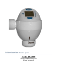
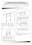
Toilet Guardian Protection Systems Model TG 1000 External Toilet Water Shut-Off Valve Installation Guide 3.1 With accompanying online video at www.AquaOne.com. Table of Contents Table of Contents.................................................................................................................................................................... 2 Features .............................................................................................................................................................................. 3 The System ............................................................................................................................................................................. 3 Ceramic Disks .................................................................................................................................................................... 3 Battery Life ........................................................................................................................................................................ 3 Protection ................................................................................................................................................................................ 3 Catastrophic Protection ...................................................................................................................................................... 3 Non-Catastrophic Protection .............................................................................................................................................. 3 Profiles .................................................................................................................................................................................... 4 Power-Save Audible Alert Sleep Mode .................................................................................................................................. 4 ALARM SILENCE Button ..................................................................................................................................................... 4 Last Event Identification ......................................................................................................................................................... 4 II. Event Icon Table ................................................................................................................................................................ 4 Event Icon Table ..................................................................................................................................................................... 4 III. Modules (some assembly required) .................................................................................................................................... 5 Parts Checklist ........................................................................................................................................................................ 5 Recommended Precautions ..................................................................................................................................................... 7 Tools/Supplies Needed ........................................................................................................................................................... 7 MCU Assembly and Battery Installation ................................................................................................................................ 7 MCU Battery Installation and Set up ................................................................................................................................. 7 Bowl Sensor, Assembly and Test............................................................................................................................................ 7 Tank Sensor, Assembly and Test ............................................................................................................................................ 8 IV. Installation on to Toilet ...................................................................................................................................................... 9 Toilet Guardian Main Control Unit (MCU) ............................................................................................................................ 9 Installation- Tank Sensor ........................................................................................................................................................ 9 Installation- Bowl Sensor ...................................................................................................................................................... 10 V. System Installation Check ................................................................................................................................................ 11 VI. Specification Diagrams .................................................................................................................................................... 12 I. List of Illustrations Figure 1: Toilet Guardian Installed .............................................................................................................................................. 6 Figure 2: Bowl Sensor Assembly ................................................................................................................................................ 7 Figure 3: Tank Sensor Assembly ................................................................................................................................................. 8 Figure 4: MCU and L Connector on Toilet.................................................................................................................................. 9 Figure 5: Tank Sensor Installation ............................................................................................................................................... 9 Figure 6: Bowl Sensor on the Bowl ........................................................................................................................................... 10 Figure 7: Bowl Sensor Assembly .............................................................................................................................................. 10 Figure 8: Completed Installation ............................................................................................................................................... 11 Figure 9: Main Control Unit (MCU) Specifications .................................................................................................................. 12 Figure 10: Bowl Sensor Specifications ...................................................................................................................................... 12 Figure 11: Tank Sensor Specifications ...................................................................................................................................... 12 Figure 12: Z Connector (optional) Specifications ...................................................................................................................... 12 Figure 13: L Connector Specifications ...................................................................................................................................... 12 Toilet Guardian Professional Installation Guide V 2.1 Page 2 of 12 I. Features The System The Toilet Guardian is an electronic water stop valve that attaches directly to the fill valve under the toilet. It consists of three major components: 1. Water Control Valve (Main Control Unit, MCU) 2. Bowl Sensor (overflow sensor) 3. Tank Sensor (water level sensor) The sensors can be used in unison or separately depending on the need of the user. When an event occurs (see: List of Events) the Toilet Guardian receives a signal from one or both sensors and if needed, shuts off the water supply to the toilet, shows an icon and gives an audible alert. These three horsemen of the apocalypse may come individually or all together. Ceramic Disks When a problem occurs the ceramic disks, within seconds, close to shut off the flow of water to the toilet. These disks are known to last over 20 years of normal use. Battery Life The Toilet Guardian has been tested to a five year life on a single 3V lithium battery.* * Based on quantity of alerts. Protection The Toilet Guardian protects two areas of the toilet: the bowl and the tank. Each area has a water level sensor that monitors the toilet for problems. The Bowl Sensor protects against bowl overflows and is set so that no water should leave the bowl. The Tank Sensor protects against leaky flappers, stuck open flappers, leaky fill valves, stuck open fill valves and most other tank leaks. Both sensors will protect against accidental or misdemeanor removal of the sensors. Protection is offered in three forms: audible warning, visual icon, water shut-off. The user may choose which solution they want by selecting from preset programs called Profiles. Water Shut-Off The main purpose of the Toilet Guardian is water shut-off. Problems are divided into two categories: Catastrophic and Non- Catastrophic. Catastrophic events require immediate water shut off and will not allow the valve to stay open until the problem has been solved. Non-catastrophic events such as leaky flappers may allow a “count” of events before water shut off. Note: Tank leak water shut off can be disabled in specific Profiles. (See: User Manual, Profile Table.) Audible Alerts:”Three beeps I’m Happy!” Continuous beeps indicate that the Toilet Guardian has closed the valve due to active alert. Three beeps in sequence indicated that the MCU is functioning normally, the valve is open and all sensors that have been installed are in standby mode. A single beep when a button has been pressed will indicate that the Toilet Guardian is NOT ready to protect. You must check to see if the valve is closed or if there is an active alert. Visual Alerts Alert icons (see: Alert Icon Table) identify the problem at hand or the last problem that was monitored. Catastrophic Protection Catastrophic events demand immediate water shut-off and cannot be “re-set” without complete resolution of the problem. Toilet bowl overflows When the Bowl Sensor is active and an alert is triggered (an overflow), the Toilet Guardian will immediately close. If opened and the water in the bowl is still above the sensor the valve immediately recloses. This insures the tank remains empty and no additional flushing can occur. Cable Disconnects When a cable is broken or disconnected the toilet is unprotected. Therefore in all instances when the MCU loses communication from an installed sensor, it will immediately close and will continue to re-close if attempts are made to open the valve without restoring communication. (See: User Manual, Toilet Guardian System Reboot for instructions on how to remove a sensor from service.) Non-Catastrophic Protection Certain Profiles allow the user to disable the water shut off feature when a Non-Catastrophic event is logged. These events include stuck open flappers and leaky or stuck fill valves. When a non-catastrophic event is set to shut off the water, reopening the valve resets the system and resets the timers. Toilet Guardian Professional Installation Guide V 2.1 Page 3 of 12 Profiles The Toilet Guardian offers multiple programs called Profiles. Each Profile allows the Toilet Guardian to react differently to events (problems) associated with the toilet. Example: A user may not want to be bothered by an audio alarm due to a non-catastrophic event. They would want a visual alert because of the costs associated with water loss. Choosing the correct Toilet Guardian profile would allow the leak to be identified on the LCD screen without an audible alarm. See: Toilet Guardian TG 1000 User Manual for a complete description of the events and actions (alerts, alarms, etc.) associated with each profile. Power-Save Audible Alert Sleep Mode After 1 minute of constant alert, the audible alert and icon will stop. The alert will then sound for 15 seconds every 5 minutes for the next 10 minutes before going to sleep. The alert will remain silent and the icon invisible until the Program Button is pressed and activates Last Event Identification. A single audible beep, after Program Button is pressed, means the valve is still closed and/or there is still a problem; three beeps means everything is okay. "Three Beeps I'm Happy." ALARM SILENCE Button During audible notification of a problem, the alarm can be silenced by pushing the ALARM SILENCE Button. The audible alarm feature can also be disabled by choosing one of several Profiles (see: User Manual, Profile Table) that offer an "ALARM SILENCE" option. Last Event Identification When the PROGRAM Button is pushed the Toilet Guardian will show the icon of the last event or multiple alert icons if multiple events are occurring. Note: The last event may still be active. II. Event Icon Table Event Icon Table Event 1 2 3 4 5 6 7 8 9 10 11 12 Icon Cause(s) Flapper Stuck Open Flapper does not seat properly. Flapper Leak Tank Leak such as leaky flapper, cracked tank, leaking bolt holes, etc. Bowl Overflow Bowl water level rises above normal. Bowl Cable Disconnect Bowl cable is removed or broken. Fill Valve Leak (Tank Overflow) Tank water level rises above normal; stuck open or leaking fill-valve. This may also occur if the Tank Sensor is set too low in the tank causing false readings. Tank Cable Disconnect Tank cable is removed or broken. Tank Sensor Waterline Error Dual Connector Cable Disconnect Water does not rest at the WATERLINE on Tank Sensor after multiple flushes. Low Battery Replace battery IMMEDIATELY. The valve fails to fully close. This symbol will appear with the event icon that was active when the valve failed to close. If the valve has not closed in six months, a self close occurs. No icon for normal toilet operation. Dual connector cable is removed or broken. Valve Close Failure Six Month Valve Test Flush All icons visible none Toilet Guardian Professional Installation Guide V 2.1 Page 4 of 12 III. Modules (some assembly required) Before installing the Toilet Guardian, check the parts list and read all instructions. Parts Checklist 1 Bowl Sensor o 1 Bowl Sensor o 1 Flat Bracket o 1 Toilet Seat Spacer o 1 Cable Guide Tube 1 Tank Sensor o 1 Tank Sensor o 1 Tank Sensor Bracket 1 Main Control Unit (MCU) o 1 Control Housing o 1 Top Cap o 1 Bottom Housing o 1 Knob o 2 Bottom Housing Screws (small) o 1 Knob Screw (medium) o 1 Battery (3v, CR2477T ) 1 Dual Connector Cable Connectors o L-Connector o Z-Connector (Special Orders Only) * The Toilet Guardian comes in three models: Bowl Only, Tank Only and Complete. Main Control Unit Top Cap Expanded View Front Dual Connector Cable Control Housing CR2477T Battery Bottom Housing Z Connector (Special Order) L Connector Small Screws Knob Flat Bracket Medium Screw Cable Guide Tube Seat Spacer Tank Sensor Bowl Sensor Tank Sensor Bracket Toilet Guardian Professional Installation Guide V 2.1 Page 5 of 12 Tank Sensor Seat Spacer Bowl Sensor Main Control Unit w/ L-Connector Figure 1: Toilet Guardian Installed **Warning** TURN OFF THE MAIN WATER LINE Before installing any water control unit or valve, it is always strongly recommended that all water to the corresponding water valve be turned off. This insures that existing broken, rusted, corroded, and/or malfunctioning valves do not cause unexpected problems. If the main water supply is NOT turned off, there is in increased risk of flooding and or substantial water damage. Toilet Guardian Professional Installation Guide V 2.1 Page 6 of 12 Recommended Precautions 1. Wear protective gloves. 2. Turn off the water supply to the location of the install. Note: Over time, most water stop valves get corroded and certain types of water can cause severe damage inside the water stop valve. Therefore, AquaOne Technologies cautions all installers, professional and do-it-yourselfers to: 1) Expect the best, plan for the worst, 2) turn the main water supply off at least once prior to any work with water lines, and if you don't 3) Know exactly where the water supply valve is for the line with which you are working and how to turn it off! 3. Clean the toilet before you start with a solution of bleach and water (1 to 10). Tools/Supplies Needed Needed Adjustable Wrench –Medium size Small Phillips Head Screwdriver Medium Phillips Head Screwdriver Large Flathead Screwdriver (for seat bolt removal). Suggested 2 –4 quart bowl ( to catch drips) Paper towel or rags to wipe the drips you missed Protective Gloves, disposable or other Small spray bottle of diluted bleach (1 part bleach to 10 parts water) MCU Assembly and Battery Installation MCU Battery Installation and Set up (See: Parts Check List) 1. 2. 3. 4. 5. 6. 7. 8. 9. Remove the Top Cap from the MCU. Remove the Knob. Remove the Bottom Housing. Replace Knob. It is keyed and will only fit one way. DO NOT FORCE. DO NOT ATTACH ANY SCREWS YET. If the OPEN line on the Knob is not already at the front of the MCU (directly under the LCD) turn the Knob to the left until the lines match. This is the position that allows water to flow freely through the MCU. Install the battery; positive side facing IN. If the valve is open, 3 beeps will sound. Insert the dual connector cable into the rear port of the Toilet Guardian. Refer to the User Manual to select the Toilet Guardian to the protection level (Profile) you plan to use. Set the Profile now. (See: Toilet Guardian TG 1000 User Manual, Profile Setting the Profile for complete directions.) Use this Profile for all the following tests. Bowl Sensor, Assembly and Test (Skip if only using the Tank Sensor.) 1. Assemble the Bowl Sensor a. b. Take the flat bracket in one hand and the bowl sensor plug in the other. Gently insert the plug through the top (smooth) side of the flat bracket. Push the cable through until the forked end of the flat bracket and bowl sensor touch. c. While holding the bowl sensor upright in one hand (smooth side against your palm) with your finger hold the cable against the sensor inside corner and insert the flat bracket into the bowl sensor. Note: The cable must fit inside the channel on the top of the flat bracket and go down through the bracket from the top. d. Plug the bowl sensor into the smaller of the dual connector cable's jacks. To avoid causing an alert, keep the sensor upright so the donut float remains at the bottom. e. Check to see that the valve is in the open position. If it is not, Figure 2: Bowl Sensor Assembly open it now by turning the knob to the left until the open line aligns with the line on the lower cover. Toilet Guardian Professional Installation Guide V 2.1 Page 7 of 12 1. 2. 3. 4. Test 1 – Bowl Overflow The bowl sensor should be in the upright position as if it were installed in the toilet. Raise the float to the top position and hold it to simulate a bowl overflow. The MCU valve should close.* As long as the sensor float remains in the top position, the valve will reclose if opened. To reset the alert return the float to the bottom position and open the MCU valve. Test 2- Bowl Sensor Cable Disconnect 1. Check to see that the MCU valve is open. If not, open it now. 2. Remove the bowl sensor plug from the dual connector cable. a. The disconnect icon will occur and an alert will sound. b. The valve should close.* 3. Reset by attaching the bowl sensor cable and opening the valve. When correctly reset three beeps will occur. (Three beeps I’m happy!) *If the valve does not close as expected during any test, See: System Installation Check at the end of this Installation Guide Tank Sensor, Assembly and Test (Skip if using only the Bowl Sensor.) Tank Sensor Assembly 1. Place the Tank Sensor on to the bracket by inserting the two square pegs on the back of the Tank Sensor through bracket with the hook side facing away from the Tank Sensor. Adjusting the Tank Sensor position on the bracket will occur later. Figure 3: Tank Test 1- Tank Overflow. Sensor Assembly 1. Open the valve on the MCU. 2. Plug the Tank Sensor into the dual connector cable. 3. Holding the Tank Sensor in the upright position, push the tank float to the top of the Tank Sensor. 4. A Tank Overflow Alert will be activated. * Test 2 – Tank Sensor Cable Disconnect 1. Open the valve. 2. Disconnect the Tank Sensor from the dual connector. The disconnect icon will occur and the valve will close. Depending on the Profile you set, and audible alert may also happen.* 3. Replace the connector and open the valve. Three beeps will occur. (Three beeps I’m happy!) *Valve shut off and audible alerts may be disabled in Profiles associated with the Tank Sensor. If any test performed does not give the expected results, see System Installation Check at the end of this Installation Guide. Final Steps before Installation onto Toilet 1. 2. 3. 4. 5. 6. 7. Disconnect all sensors from the dual connector cable and then disconnect the dual connector cable from the MCU. Reboot the system by removing the battery, pushing the PROGRAM button then replacing the battery. This allows the user to install and test each sensor without creating cable disconnects alerts. Reset the Profile. Securely fasten the Bottom Housing using the two small screws. Make sure a line on the Bottom Housing faces the front of the MCU. DO NOT OVER TIGHTEN. Push the knob onto the keyed shaft. It fits only one way. DO NOT FORCE. Attach with the medium screw. Grip the Knob securely while tightening the screw. DO NOT OVER TIGHTEN! Replace the Top Cap. IMPORTANT!! If a user would like to convert to a single sensor system or switch from bowl only to tank only or vice versa, a System Reset must occur. A System Reset is done by removing the battery and pushing the PROGRAM Button once then reinserting the battery. Please see the Procedures Section in the User Manual for further details. Note: If System Reset instructions have been followed, Profile 1 is now active. Do not change until full installation is completed. Toilet Guardian Professional Installation Guide V 2.1 Page 8 of 12 IV. Installation on to Toilet Toilet Guardian Main Control Unit (MCU) 1. 2. Get the L Connector and the MCU. Make sure a rubber cone washer is properly seated inside each end of the L Connector (small end of cone facing out). 3. Attach the short end of the L Connector to the back side (outlet) of the MCU. The L Connector only fits to the MCU one way. Hand tighten. 4. Insert the dual connector cable into the back of the MCU. Note: It only fits one way so DO NOT FORCE! 5. Set aside. 6. Turn off the water supply to the toilet at the water stop valve. 7. Flush the toilet to remove most of the water from the toilet tank. 8. Have a small container ready to catch any water that may be left in the fill line or the fill valve. 9. Remove the fill line from the bottom of the toilet fill valve. 10. Attach the MCU/L Connector assembly to the bottom of the fill valve. Hand tighten! 11. Make sure there is a washer inside the fill valve line. 12. Attach the fill line to the inlet side of the MCU. Hand tighten! Figure 4: MCU and L Connector on Toilet 13. Turn the water back on and open the valve. 14. Check for leaks. 15. MAKE SURE THE KNOB CAN TURN FREELY!! a. If any leaks are found quickly turn off the water. Check to see that all connections are properly tightened. Check to insure washers were properly installed and in excellent condition. Installation- Tank Sensor (Skip if using the Bowl Only configuration.) Figure 5: Tank Sensor Installation 1. Remove the tank lid and set aside. 2. Flush the toilet several times to see that the fill valve is functioning properly and that the tank's water level is the same after each flush. The water should fill to about 1" below the top of the overflow (fill) tube. 3. Get the Tank Sensor. 4. Place the Tank Sensor inside the tank with the cable hanging outside the tank. (The rear of the tank away from the fill valve often works best.) a. Make sure the Tank Sensor float can rise freely and does not interfere with the operation of either the fill valve or the flapper. 5. Run the cable down the back of the tank. 6. Plug the Tank Sensor into the larger plug on the dual connector cable. 7. Test by lifting the Tank Sensor float to the top of the Tank Sensor and holding. This will activate a Fill Valve Leak alert. 8. If the Fill Valve Leak icon appears on the LCD screen, then the Tank Sensor is working properly. 9. Adjust the Tank Sensor so that the top of the water in the tank is along the WATERLINE mark on the sensor. Note: If the Tank Sensor Waterline is set at the top of the fill tube, there is a potential for the water not to shut off due to a stuck open or leaky fill valve. Flush the tank to see that the water level rises to WATERLINE mark. 10. Replace the tank lid. Note: If the water level is not properly adjusted, the Tank Sensor Water Line Error alert will activate. If the user must continually adjust the tank senor, use a permanent marker to mark the position of the Tank Sensor on the Tank Sensor bracket. Then, if the Tank Sensor is not moving on the bracket, and the alert is continually activated, the fill valve is NOT working properly and should be repaired or replaced. Toilet Guardian Professional Installation Guide V 2.1 Page 9 of 12 Installation- Bowl Sensor (Skip if using the Tank Only configuration.) 1. Remove the toilet seat and set aside. 2. Get the Bowl Sensor assembly 3. Take the bowl sensor cable and gently feed the plug through the seat bolt hole on the Toilet Guardian side of the toilet. Pull the sensor cable from below the toilet rim until the bowl sensor rests snugly against the inside rim of the toilet bowl. (See: Figure 7: Bowl Sensor Assembly). a. At this time you should be able to release the bowl sensor cable and the bowl sensor should hang loosely inside the rim. 4. Plug the Bowl Sensor Cable into the dual connector cable's small jack. Note: Make sure the bowl sensor float can rise freely. Some toilets may require an outward adjustment of the flat bracket so that the float on the sensor moves freely. 5. Test by lifting the Bowl Sensor float to the top and holding. This will activate a Bowl Overflow alert. 6. If the Bowl Overflow icon appears on the LCD screen and the valve closes, the Bowl Sensor is working properly. Figure 6: Bowl Sensor on the Bowl 7. Open the valve. 8. Gently place the seat back on the toilet while holding the cable against the front of the bolt hole. 9. Carefully slide the seat bolt down through the bolt hole while continuing to hold the cable firmly against the front of the bolt hole. 10. Slide the cable guide tube onto the bolt with the slot facing towards the front. The prongs at the top of the cable guide tube will fit into the bolt hole and the cable will run in the slot at the front of the cable guide tube. 11. Being careful NOT let the cable guide tube turn, replace the seat bolt nut but only tighten a couple of turns. 12. Insert the other seat bolt. 13. Lift up the non- sensor side of the seat, slide the toilet seat spacer onto the bolt (between the bowl and the seat). 14. Replace the second seat bolt nut but only tighten a couple of turns. 15. Now is the time to adjust the bowl sensor position against the rim, if needed. To adjust the position, remove the seat bolt and slide the flat bracket in or out as needed. Figure 7: Bowl Sensor Assembly 16. Tighten both seat bolt nuts being sure to NOT let the cable guide tube turn. Warning!!! Replacing the toilet seat must be done carefully to avoid pinching the cable. An improperly installed bowl sensor cable can result in a broken cable and cause unwarranted disconnect alerts and/or failure of the MCU valve to close for a bowl overflow incident. The bowl sensor cable guide tube must always be installed. Toilet Guardian Professional Installation Guide V 2.1 Page 10 of 12 V. System Installation Check 1. 2. 3. 4. 5. Did you turn the water on? Did you check for leaks? Did you install/reinstall the battery? Are the Bottom Housing and the knob securely fastened? When the Program button is pushed, does your chosen Profile appear in the bottom left hand of the LCD screen? 6. Is the sensor(s) you plan to use plugged into the dual connector cable? 7. Is the Dual Connector Cable seated firmly in the back of the MCU? 8. Did you complete a sensor check? 9. Is the Top Cap back on? 10.Does the knob on the MCU turn freely when closed? If you answered yes to all the above questions, you have completed installation. Figure 8: Completed Installation Toilet Guardian Professional Installation Guide V 2.1 Page 11 of 12 VI. Specification Diagrams Out ↑ In → Figure 9: Main Control Unit (MCU) Specifications Figure 10: Bowl Sensor Specifications Figure 12: Z Connector (optional) Specifications Figure 11: Tank Sensor Specifications Figure 13: L Connector Specifications Toilet Guardian Professional Installation Guide V 2.1 Page 12 of 12