1
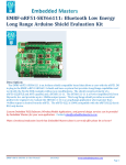
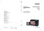
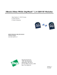
MEGA Multifunction I/O Shield User Manual PN: 2020 Berkshire Products, Inc. Phone: 770-271-0088 http://www.bkp-store.com/ Rev: 1.00 © Copyright 2013 MEGA Multifunction I/O Board User Manual Table of Contents 1 2 3 4 5 6 7 8 Introduction................................................................................................................. 2 Features ....................................................................................................................... 2 2.1 Real Time Clock chip ......................................................................................... 2 2.2 Wiznet 5100 Ethernet interface .......................................................................... 2 2.3 XBee Radio socket.............................................................................................. 2 2.4 LCD Interface ..................................................................................................... 3 2.5 Micro SD card socket.......................................................................................... 3 2.6 Other ................................................................................................................... 3 XBee Radio Support ................................................................................................... 4 Configuring the Board ................................................................................................ 5 4.1 DC Power Input .................................................................................................. 5 4.2 I/O Selection Jumpers ......................................................................................... 6 4.2.1 Ethernet (ETH-CS) I/O SPI Selection – J9................................................. 6 4.2.2 Micro SD Card (SD-CS) I/O SPI Selection – J10 ...................................... 6 4.2.3 Ethernet Interrupt (ETH-IRQ) I/O Selection – J11..................................... 6 4.2.4 RTC Watchdog Output (WDO) MEGA Reset – J13.................................. 6 4.2.5 RTC Interrupt (RTC-RIQ) I/O Selection – J14 .......................................... 7 4.3 Buzzer ................................................................................................................. 7 4.4 XBee Communications Selection ....................................................................... 7 4.4.1 XBee RSSI Signal....................................................................................... 7 4.5 Micro SD Card – J4 ............................................................................................ 7 4.6 LCD Interface – J15 & J18 ................................................................................. 8 4.7 Battery Socket – BT1.......................................................................................... 8 Configuring the XBee Radio ...................................................................................... 9 5.1 Starting X-CTU................................................................................................. 10 5.2 Configuring the Networking ............................................................................. 11 5.3 Configuring the Addressing.............................................................................. 12 5.4 Configuring the Serial Interfacing .................................................................... 13 5.5 Configuring I/O Settings................................................................................... 14 5.6 Configuring I/O Sampling ................................................................................ 15 Schematic Diagram................................................................................................... 16 Appendix A – Specifications .................................................................................... 19 Appendix B - Warranty............................................................................................. 20 Rev 1.00 i 7/17/2013 MEGA Multifunction I/O Board User Manual The latest versions of manuals, sample code and other tools can be found on our site at: http://bkp-store.com/ If you have any questions, corrections, or feedback about this manual please contact us at: http://bkp-store.com/index.php?route=information/contact Rev 1.00 1 7/17/2013 MEGA Multifunction I/O Board User Manual 1 Introduction The MEGA Multifunction board provides multiple I/O capability for Ardiuno boards using the MEGA form factor. Examples are the MEGA and the MEGA 2560 as well as the SainSmart Mega 2560. 2 Features The board has the following features: 2.1 Real Time Clock chip - Microchip MCP795W10 (20). Coin cell holder on underside of PCB. Includes 64 bytes of user battery backed RAM 1K or 2K bits of EEPROM (128 x 8 or 256 x 8) Unique ID area for MAC address Calibration register to fine tune clock frequency (plus or minus) Watchdog timer with output jumper option to reset Mega IRQ output with option jumper for Alarms Two alarm option timers Time/Date registers to store time/date when power is lost and when power is restored. 2.2 Wiznet 5100 Ethernet interface - Two chip selects available on 3 pin header. One is for standard IO pin. Allows you to have 2 Ethernet Ports (with library update). Full debug LEDs on RJ-45 jack and the PCB. Comes with unique MAC address stored in RTC ID registers so you can have multiple boards safely on the same net. MAC sticker is on the back of the PCB. 2.3 XBee Radio socket - Rev 1.00 Jumper selection to connect XBee radio to Serial Port 1, 2 or 3 on Mega. RSSI output connected to Mega analog input pin with filter. Supports all XBee & XBeePro radios in Series 1 or 2 footprint (DigiMesh 2.4G & 900MHz, 802.15.4, 900MHz, 868MHz, Zigbee, & WiFi). On-board LEDs for TxD & RxD activity. 2 7/17/2013 MEGA Multifunction I/O Board User Manual 2.4 LCD Interface - Two 16-Pin headers (2x8 and 1x16) to support most LCD displays All control lines connected, including R/W, so you can read back display data and device ready status. 8 bit data bus connected to Port A, IO22-29 for fast byte wide I/O. +5V & GND provided on Pins 15 & 16 for back lit displays Trim pot on board for contrast angle adjustment Buffered E signal for longer cable runs 2.5 Micro SD card socket - Two chip selects available on 3 pin header. One is for standard IO pin. Allows you to have 2 micro SD cards (with library update). Card inserted switch input available to check if card present. 2.6 Other - Rev 1.00 Buzzer for audible alarms Reset Switch High Current on-board +5V & 3.3V regulators to support all types of XBee radios and back lit LCD displays. Power on LED. Multi-layer circuit board. 3 7/17/2013 MEGA Multifunction I/O Board User Manual 3 XBee Radio Support The Remote I/O boards are used with XBee1 radio modules to allow remote digital sensing and remote digital output control. These boards are designed to use very little power except when the radios are transmitting data. The board can be used with the following types of XBee & XBeePro radios in Series 1 & 2 footprints: DigiMesh2 2.4G DigiMesh2 900MHz 802.15.4 900MHz 868MHz Zigbee WiFi For best results we recommend that you use XBee radios with the RP-SMA antenna connector or the mini whip antenna. These will experience the least interference from the copper areas on the PCB. The XBee radios with chip and PCB antennas will still work but their range may be reduced. Note 1: XBee is a registered trademark of Digi International Inc. Note 2: DigiMesh is a registered trademark of Digi International Inc. Rev 1.00 4 7/17/2013 MEGA Multifunction I/O Board User Manual 4 Configuring the Board Refer to following PCB diagram for component placement and header selection: Figure 4-1 4.1 DC Power Input This board requires external power to operate. Plug in a DC power source of 9V DC into the 2.1mm power jack on the MEGA board. You can go as high as +15V although the regulators on the MEGA board may get warm powering the MEGA circuitry. Note: Do not exceed +18V supply input to the board! The power supply must able to source enough current to power the board and the XBee radio in TX mode. This will typically be up to 500mA (0.5A) for the higher powered XBee radios. The input pre-regulator on the board is an 80% switcher supplying +5V volts so your input supply needs to provide about 3.1W. If you have a +9V DC supply then it should be rated at 350mA minimum. In the upper left corner of the board is a power LED. Rev 1.00 5 7/17/2013 MEGA Multifunction I/O Board User Manual 4.2 I/O Selection Jumpers There are some 2 and 3 pin jumpers on the board for setting the options for the on-board circuits. The board is shipped with the jumpers in default mode. Pin 1 is on the left side of the jumpers and is labeled on the PCB. 4.2.1 Ethernet (ETH-CS) I/O SPI Selection – J9 The Wiznet Ethernet chip is connected the SPI Bus on the MEGA board. The SPI Chip Select pin is set with this jumper as follows: Pins 1-2: Pins 2-3: IO10 – default for Arduino Ethernet library IO31 – alternate 4.2.2 Micro SD Card (SD-CS) I/O SPI Selection – J10 The Micro SD card chip is connected the SPI Bus on the MEGA board. The SPI Chip Select pin is set with this jumper as follows: Pins 1-2: Pins 2-3: IO04– default for Arduino SD library IO30 – alternate 4.2.3 Ethernet Interrupt (ETH-IRQ) I/O Selection – J11 The IO pin for the Ethernet interrupt is set with this jumper as follows: Pins 1-2: Pins 2-3: IO02– default for Arduino Ethernet library A15 – alternate 4.2.4 RTC Watchdog Output (WDO) MEGA Reset – J13 This jumper allows the RTC chip to reset the MEGA processor if the RTC Watchdog times out. It is shipped with the jumper on pin 1 only. Move the jumper across both pins to enable the reset. The WDO output from the RTC is an open drain. Pin 1 Only: Pins 1-2: Rev 1.00 Default Direct connect to MEGA Reset line. 6 7/17/2013 MEGA Multifunction I/O Board User Manual 4.2.5 RTC Interrupt (RTC-RIQ) I/O Selection – J14 The IO pin for the RTC interrupt is set with this jumper as follows: Pins 1-2: Pins 2-3: IO03– default A14 – alternate Note: The current library code for the RTC does not have interrupt support. That will have to be added by the end user. 4.3 Buzzer The buzzer is hard wired to IO33. Turn the buzzer on by setting the pin High. 4.4 XBee Communications Selection The XBee radio requires a TxD and an RxD line for communications. The jumper J5 allows you to select one of the extra three (3) serial ports on the MEGA board to talk to the module as follows: Pins 1-2 & 3-4: Pins 5-6 & 7-8: Pins 9-10 & 11-12: Serial Port1 – default Serial Port2 Serial Port3 Note: The jumpers should be moved in pairs. In the upper right corner of the board are two SMT LEDs labeled XOUT & XIN that show communications activity with the XBee module. 4.4.1 XBee RSSI Signal The XBee module can be programmed to show the RSSI: Relative Signal Strength Indicator via a PWM output. This out is filtered and connected to the analog pin A13. 4.5 Micro SD Card – J4 The socket at J4 is for a micro SD card. It is a push-in / push-out type jack. The card inserted switch output from the jack is hard-wired to IO32. The input will read low when a card is inserted. Rev 1.00 7 7/17/2013 MEGA Multifunction I/O Board User Manual 4.6 LCD Interface – J15 & J18 The LCD interface is handled on J15 & J18. One header is 1x16 and the other is 2x8 for industry standard LCD connections. The eight (8) bit data bus is hard-wired to IO22-29. The other pins for the LCD are hard-wired as follows: LCD-E: LCD-R/W: LCD-RS: IO37 IO36 IO35 An updated library is available that makes full use of the full 8-bit parallel interface for higher speed access. The library has also been updated to read back status from the LCD to know when it is ready for new operations rather than using large wait timers. Both LCD headers have +5V and Ground available on pins 15 & 16 to supports backlighting. There is also a trim pot (R22) to adjust contrast on LCDs that support the option. 4.7 Battery Socket – BT1 The battery socket holder is on the back of the PCB. It will accept battery sizes 1212, 1216, 1220, & 1225. Be careful of polarity when inserting the battery. Notice that the metal tab on the battery socket is the plus (+) terminal. Rev 1.00 8 7/17/2013 MEGA Multifunction I/O Board User Manual 5 Configuring the XBee Radio The examples shown here use an XBee 2.4G DigiMesh version with Digi’s X-CTU software which is free and available from Digi International (www.digi.com). To program the radios we use the UARTSBee V4 device which provides power and a USB UART connection to the PC. They are available from Amazon (www.amazon.com) and other sources and look similar to this picture: Figure 5-1 These devices are also useful for connecting to your PC to use as the “base station” to talk back and forth with the remote I/O module’s XBee radio. Note: Be aware that this board may not be able to supply enough power for an XBee Pro type radio if you plug it into a USB hub. Note: When the device is first plugged in you may get an alert from your PC that it needs to install drivers for a new device. The UARTSBee uses the FTDI chip for USB to Serial conversion and most PCs have these drivers pre-installed. If yours doesn’t, go to www.ftdi-chip.com to get the latest ones for your PC and OS. Rev 1.00 9 7/17/2013 MEGA Multifunction I/O Board User Manual 5.1 Starting X-CTU When you start X-CTU you should see a screen like the following: Figure 5-2 In this example the USB → Serial was on COM4. The baud rate should be 9600 to start with, since that is how the XBees are shipped from Digi. Click the Test / Query button to see if the XBee is active. If so, you should get a window like this: Figure 5-3 Is this case the test was OK. It found an XB24 or a 2.4G DigiMesh. If it had been the higher power Pro it would have been XBP24. The firmware version is shown along with its serial number (IEEE Address) which is HEX: 0013A200 40870B85. The address is always 8 Bytes (64 bits) and leading zeros are not shown. Most Digi XBees start with 0013A200. It is also shown on the label on the bottom of the module. Rev 1.00 10 7/17/2013 MEGA Multifunction I/O Board User Manual 5.2 Configuring the Networking The next step is to click the Modem Configuration tab and then press the Read button to get a screen like the following: Figure 5-4 Under the Networking section there are options that you can change. Note that different types of modules will have different options. The ones shown here are for DigiMesh. For this module type the only two changes that we will talk about are the VID and the Channel. Modem VID: This is a HEX number that sets the PAN (Personal Area Network) ID for the network. Valid range is 0-0xFFFF. All the XBees on your network should use the same VID. Operating Channel: This sets the operating channel number (Uses 802.15.4 channel numbers). Note two things here: 1. XBee modules have more channels available than XBee Pro modules, so be sure to select an operating channel that both types can use if you have mixed modules on your network. 2. Select a channel number that minimizes conflict with any Wi-Fi networks you have. There are docs on the web that show 802.15.4 channel assignments. See the Digi manual for specifics on other networking options. Rev 1.00 11 7/17/2013 MEGA Multifunction I/O Board User Manual 5.3 Configuring the Addressing XBee modules talk to each other using their serial numbers or a 16 bit addressing scheme. We will show the 802.15.4 64 bit scheme here. The Digi XBee manuals show you how to use short addresses. Figure 5-5 In this example we are programming a module for an I/O board that will talk to a host module (base station) at regular intervals. So in this case we set the High order 4 Bytes to the standard XBee address of 0x0013A200 and the lower 4 bytes to the address of our base station module 0x40883039. Once this is set, the module will know what address to send API packets to when an input changes or when a sample must be sent. Rev 1.00 12 7/17/2013 MEGA Multifunction I/O Board User Manual 5.4 Configuring the Serial Interfacing There are a few options to set here: Figure 5-6 One option that needs setting here is the API enable. API mode must be enabled if the XBee module on the I/O board is going to be able to transmit input pin information and set the outputs. API mode 2 is used by the Arduino XBee library if you plan to use an Arduino type board as your base station. Also note that the Digital I/O pins DIO6 and DIO7 are configured here. The reason for that is they can also be used as serial port flow control pins. If you are using DIO6 and DIO7 on your module then you should configure them here as Inputs or Outputs. Rev 1.00 13 7/17/2013 MEGA Multifunction I/O Board User Manual 5.5 Configuring I/O Settings Here is where you configure the I/O pins for DIO0 to DIO5 (see prior section for DIO6 & DIO7). These IO pins are available on headers J6 & J8. Figure 5-7 Configure DIO0 to DIO5 pins as input or output to match your I/O board setup. DIO8 to DIO12 are not used and should be left as 0-Disabled. The PR field defaults to 0x1FFF or binary 1 1111 1111 1111. Each bit set to one (1) defines a pull-up resistor on input pins DIO12 to DIO0. The default values should be fine unless you are using the input pins for analog inputs. In that case the lower six bits should be zero for any pin that is an analog input. Rev 1.00 14 7/17/2013 MEGA Multifunction I/O Board User Manual 5.6 Configuring I/O Sampling This is the last area of X-CTU covered here: Figure 5-8 The DIO Change Detect is a bit field and should be set to a hex value. Any bit that is set will cause the XBee to send a packet when the I/O line for that bit changes (goes low to high or high to low) and the pin is set as an input. For example if you set this field to 0x2C (binary 0100 1100) then it would send a data packet if DIO6, DIO3 or DIO2 changes state on its input. The Sample Rate tells the XBee module to send a data packet at regular intervals to report the status of digital and analog input pins. The number is in milliseconds so a reasonable minimum value is about 0x80 or 128mS. If an edge change is programmed and it occurs between samples then a packet will be sent then as well. The maximum value for this field is 0xFFFF or 65,353mS. A value of zero stops the samples. Rev 1.00 15 7/17/2013 MEGA Multifunction I/O Board User Manual 6 Schematic Diagram Rev 1.00 16 7/17/2013 MEGA Multifunction I/O Board User Manual Rev 1.00 17 7/17/2013 MEGA Multifunction I/O Board User Manual Rev 1.00 18 7/17/2013 MEGA Multifunction I/O Board User Manual 7 Appendix A – Specifications Power Requirements: 8V DC @ 400mA – minimum 18V DC maximum @ 200mA Do not exceed +18V input. The MEGA board could be damaged. Environmental: -40° to +85°C - Operating -40° to +85°C - Storage 5% to 95% Relative Humidity, non-Condensing Rev 1.00 19 7/17/2013 MEGA Multifunction I/O Board User Manual 8 Appendix B - Warranty Berkshire Products, Inc. warrants to the original consumer or other end user purchaser that this product is free from defects in materials or workmanship for a period of one (1) year from the date of purchase. During the warranty period, and upon proof of purchase, the product will be repaired or replaced (with the same or functionally equivalent model) at our option, without charge for either parts or labor. This warranty does not apply to defects due directly or indirectly to misuse, abuse, negligence, accident, repairs or alterations made by the customer or another party. UNDER NO CIRCUMSTANCES WILL BERKSHIRE PRODUCTS, INC. BE LIABLE IN ANY WAY TO ANY PURCHASER FOR DAMAGES, LOST REVENUE, LOST WAGES, OR ANY OTHER INCIDENTAL OR CONSEQUENTIAL DAMAGES ARISING OUT OF THE USE OR INABILITY TO USE THIS PRODUCT. Berkshire Products, Inc. reserves the right to make modifications in this product without prior notification. Rev 1.00 20 7/17/2013