1
MICROCOMPUTER
MN10300
MN10300 Series
Cross-Assembler
User’s Manual
Pub.No.13110-051E
PanaXSeries is a trademark of Matsushita Electric Industrial Co., Ltd.
Sun and Sun OS are trademarks of Sun Microsystems Inc.
HP and HP-UX are trademarks of Hewlett-Packard Corporation.
MS-DOS is a registered trademark of Microsoft Corporation.
AT is a registered trademark of International Business Machine, Corp.
UNIX is a registered trademark of X/Open Co., Ltd. in U.S. and other countries.
MIFES s a trademark of Megasoft., Inc.
The other corporation names, logotype and product names written in this book are trademarks or registered trademarks of their
corresponding corporations.
Request for your special attention and precautions in using the technical
information and semiconductors described in this book
(1)
An export permit needs to be obtained from the competent authorities of the Japanese Government if
any of the products or technologies described in this book and controlled under the "Foreign Exchange
and Foreign Trade Law" is to be exported or taken out of Japan.
(2)
The contents of this book are subject to change without notice in matters of improved function. When
finalizing your design, therefore, ask for the most up-to-date version in advance in order to check for any
changes.
(3)
We are not liable for any damage arising out of the use of the contents of this book, or for any
infrigement of patents or any other rights owned by a third party.
(4)
No part of this book may be reprinted or reproduced by any means without written permission from our
company.
If you have any inquiries or questions about this book or our semiconductors, please contact one of our sales
offices listed at the back of this book or Matsushita Electronics Corporation's Sales Department.
About
This
Manual
This Manual describes the functions of and operating procedures for the cross-assembler system for the MN10300
Series of 32-bit microcomputers.
■ Features of This Manual
• It provides a chapter covering setup, programming development flow, and introductory operation so that beginners
take only a short time to grasp the essentials and master operation.
• It provides a separate chapter on the optimization functions that are such an important feature of this system.
• It contains plentiful examples of assembler and linker operation and many programming examples.
• It explains assembler directives, assembler control statements, and macro control instructions individually with usage
specifications, usage notes, and examples.
• It also describes the use of the library manager tool for managing libraries.
• It provides personal computer users with coverage of the ways in which that version differs from the workstation
version.
• Appendices list machine instructions and error messages.
■ How to read
Heading
Chapter 16
Notes On The Operating Environment
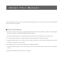
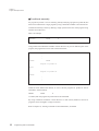
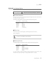
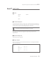
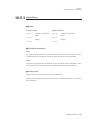
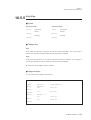
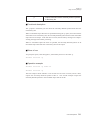
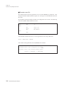
16.2.5 Environment Settings
Before using the MN10300 Series Cross-Assembler, verify or change the following two
files.
If FILES and BUFFER specifications do not already exist in CONFIG.SYS, then you
must add them. If they do already exist, then check their settings, and change them if
necessary.
Program example
FILES=20
BUFFERS=20
Usage note
Be sure to make these settings. If the assembler is started without them, then the
error message "bad tmpbss(w)" will be output and processing will stop. This
means that the number of files that can be opened simultaneously is insufficient.
Supplementary explanation
Terminology ❑ CONFIG.SYS
This is the file that sets the MS-DOS operating environment. FILES specifies the number of files that
can be read and written simultaneously.
BUFFERS specifies the size of memory used for reading/writing disks.
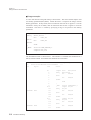
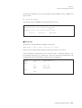
■ AUTOEXEC.BAT
To be able to run the software simply by typing in its name, include its directory in the
path search list given by the environment variable PATH.
Under MS-DOS, adding the directory in which the software is installed to the PATH
variable and activating the new value for PATH allows you to run the programs in this
system simply by entering their names.
SET PATH=A:\usr\local\bin
328
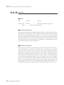
Personal Computer Versions
• Heading
Chapter titles are shown here on each page, so the reader can get a quick idea of contents while flipping through the
pages.
• Program example
These are actual examples of command options and instructions used by the assembler. First-time users should refer
to these examples when trying to use the assembler.
• Usage note
These give important information. Usage note provide cautions about usage, so they should always be read.
• Supplementary explanation
These are hints and terminology definitions that can help the reader use the assembler.
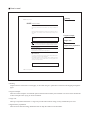
■ Reference Techniques
■ Table Of Contents
Table Of Contents
■ Chapter Contents
Main Contents
5.2
Chapter5
■ Index
Index
• Main Contents
This shows the main contents of this manual. Use it to look up the start of each chapter.
• Table Of Contents
This shows the title of all sections of this manual.
• Chapter Contents
Located at the start of each chapter, this shows the titles of all sections in that chapter.
• Index
Refer to the index at the back of this manual to look up technical terms.
Starting The Assembler
■ Related Documents
The following related manuals are available. Please contact your sales representative for more details.
● "MN103S00 Series Instruction Manual"
<Describes the instruction set>
● "MN10300 Series C Compiler User's Manual: Usage Guide"
<Describes the setup, the commands, and options of the C
Compiler>
● "MN10300 Series C Compiler User's Manual: Language Description"
<Describes the syntax of the C Compiler>
● "MN10300 Series C Compiler User's Manual: Library Reference"
<Describes the the standard library of the C Compiler>
● "MN10300 Series C Source Code Debugger User's Manual"
<Describes the use of the C source code debugger>
(NOTE: Not required for C Source Code Debugger for Windows users.)
● "MN10300 Series C Source Code Debugger for Windows User's Manual"
<Describes the use of the C source code debugger for Windows>
● "MN10300 Series Installation Manual"
<Describes the installation of the C compiler, cross-assembler and C
source code debugger and the procedure for bringing up the in-circuit
emulator>
Main Contents
Table of Contents
Table of Contents
Chapter 1
Getting Started
1
Chapter 2
Program Development Flow
2
Chapter 3
Introduction To Operation
3
Chapter 4
Optimization
4
Chapter 5
Using The Assembler
5
Chapter 6
Using The Linker
6
Chapter 7
Types Of Source Statement
7
Chapter 8
Writing Source Statements
8
Chapter 9
Writing Machine Language Instruction
Statements And Directive Statements
9
Chapter 10
Writing Assembler Control Statements
Chapter 11
Writing Macro Control Statements
Chapter 12
List Of Machine Language Instructions
Chapter 13
Error Messages
Chapter 14
Reading List Files
Chapter 15
Using The Library Manager
Chapter 16
Notes On The Operating Environment
Chapter 17
Appendix
Index
10
11
12
13
14
15
16
17
Index
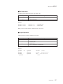
Table of Contents
1. Getting Started
1.1 Purpose Of This Chapter .....................................................................................2
1.2 Operating Environment ........................................................................................3
1.3 File Organization..................................................................................................4
1.4 Installation............................................................................................................5
1.5 Setup ...................................................................................................................6
1.6 File Conversion Utility ........................................................................................12
2. Program Development Flow
2.1 Purpose Of This Chapter ...................................................................................16
2.2 Program Development Flow ..............................................................................17
2.3 Programming With The Assembler ....................................................................19
3. Introduction To Operation
3.1 Purpose Of This Chapter ...................................................................................26
3.2 Files Used By Assembler And Linker ................................................................27
3.3 Basic Operation Of Assembler and Linker.........................................................29
3.4 Assembling And Linking Multiple Sections ........................................................35
3.5 Conditional Assembly And Linking ....................................................................45
4. Optimization
4.1 Purpose Of This Chapter ...................................................................................52
4.2 Rules Of Usage .................................................................................................53
4.3 Usage Example .................................................................................................54
5. Using The Assembler
5.1 Purpose Of This Chapter ...................................................................................70
5.2 Starting The Assembler .....................................................................................71
5.3 Command Options .............................................................................................75
5.3.1 Output File Options..................................................................................76
5.3.2 Error Message Options............................................................................83
5.3.3 Preprocessor Options ..............................................................................90
MN10300 Cross Assembler
5.3.4 Program Generation Options...................................................................92
5.3.5 Other Options ..........................................................................................95
5.4 Operation Example ............................................................................................97
6. Using The Linker
6.1 Purpose Of This Chapter .................................................................................100
6.2 Starting The Linker ..........................................................................................101
6.3 Command Options ...........................................................................................104
6.3.1 Output File Options................................................................................105
6.3.2 Error Message Options..........................................................................108
6.3.3 Program Generation Options .................................................................115
6.3.4 Library File Options ...............................................................................122
6.3.5 Other Options ........................................................................................124
6.4 Instruction RAM Support..................................................................................127
6.4.1 Structure Of IRAM Support Executable File ..........................................128
6.4.2 IRAM Support Options...........................................................................131
6.4.3 Operation Examples ..............................................................................134
7. Types Of Source Statements
7.1 Purpose Of This Chapter .................................................................................138
7.2 Program Format...............................................................................................139
7.3 Machine Language Instruction Statements And Directive Statements ............141
7.4 Assembler Control Statements ........................................................................142
7.5 Macro Control Statements ...............................................................................143
7.6 Comment Statements ......................................................................................144
7.7 Blank Statements.............................................................................................144
8. Writing Source Statements
8.1 Purpose Of This Chapter .................................................................................146
8.2 Permitted Characters .......................................................................................147
8.3 Numbers ..........................................................................................................148
8.4 Character Constants ........................................................................................151
MN10300 Cross Assembler
8.5 Address Constants ..........................................................................................153
8.6 Location Counter .............................................................................................154
8.7 Expressions .....................................................................................................155
8.7.1 Operators...............................................................................................156
8.7.2 Expression Evaluation ...........................................................................158
8.7.3 Expression Syntax .................................................................................160
8.7.4 Expression Attributes.............................................................................161
8.8 Reserved Words ..............................................................................................163
9. Writing Machine Language Instruction
Statements And Directive Statements
9.1 Purpose Of This Chapter .................................................................................166
9.2 Instruction Statement Fields ............................................................................167
9.2.1 Writing The Label Field..........................................................................168
9.2.2 Writing The Operation Field...................................................................169
9.2.3 Writing The Operand Field.....................................................................169
9.2.4 Writing The Comment Field ...................................................................170
9.3 Writing Machine Language Instruction Statements .........................................171
9.4 Writing Directive Statements............................................................................172
9.4.1 section ...................................................................................................173
9.4.2 align .......................................................................................................175
9.4.3 end.........................................................................................................177
9.4.4 listoff, liston ............................................................................................178
9.4.5 notation ..................................................................................................179
9.4.6 org .........................................................................................................181
9.4.7 opt..........................................................................................................183
9.4.8 page.......................................................................................................185
9.4.9 radix .......................................................................................................186
9.4.10 dc .........................................................................................................188
9.4.11 ds .........................................................................................................190
9.4.12 dw ........................................................................................................192
9.4.13 dd.........................................................................................................193
MN10300 Cross Assembler
9.4.14 equ.......................................................................................................194
9.4.15 global ...................................................................................................196
9.4.16 tit ..........................................................................................................198
9.4.17 xlistoff, xliston ......................................................................................199
9.4.18 funcinfo ................................................................................................200
10.Writing Assembler Control Statements
10.1 Purpose Of This Chapter ...............................................................................204
10.2 #include .........................................................................................................205
10.3 #define ...........................................................................................................207
10.4 #undef ............................................................................................................208
10.5 Conditional Assembly ....................................................................................209
10.5.1 #ifdef , #ifndef ......................................................................................211
10.5.2 #if , #ifn ................................................................................................213
10.5.3 #ifeq , #ifneq ........................................................................................215
10.5.4 #iflt , #ifle .............................................................................................217
10.5.5 #ifgt , #ifge ...........................................................................................219
10.5.6 #ifb , #ifnb ............................................................................................221
11.Writing Macro Control Statements
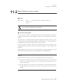
11.1 Purpose Of This Chapter ...............................................................................226
11.2 Macro Definition (macro , endm)....................................................................227
11.3 Macro Calls And Expansion ...........................................................................229
11.4 Macro Operators ............................................................................................231
11.5 Local Symbol Declaration (local)....................................................................233
11.6 Forced Termination Of Macro Expansion (exitm ...........................................235
11.7 Purging Macro Definitions (purge) .................................................................237
11.8 rept .................................................................................................................238
11.9 irp ...................................................................................................................240
11.10 irpc ...............................................................................................................242
MN10300 Cross Assembler
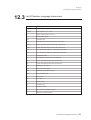
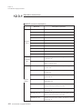
12.List Of Machine Language Instructions
12.1 Purpose Of This Chapter ...............................................................................246
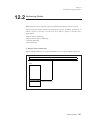
12.2 Addressing Modes .........................................................................................247
12.3 List Of Machine Language Instructions .........................................................251
12.3.1 Data Move Instructions ........................................................................252
12.3.2 Arithmetic Instructions .........................................................................259
12.3.3 Logical Instructions ..............................................................................262
12.3.4 Bit Manipulation Instruction .................................................................265
12.3.5 Branching Instructions .........................................................................267
12.3.6 User-Defined Instructions ....................................................................271
12.3.7 Other Instructions ................................................................................271
13.Error Messages
13.1 Purpose Of This Chapter ...............................................................................274
13.2 Assembler Errors ...........................................................................................275
13.2.1 Warning Messages ..............................................................................275
13.2.2 Error Messages ...................................................................................277
13.2.3 Fatal Error Messages ..........................................................................281
13.3 Linker Errors ..................................................................................................282
13.3.1 Warning Messages ..............................................................................282
13.3.2 Error Messages ...................................................................................283
13.3.3 Fatal Error Messages ..........................................................................285
14.Reading List Files
14.1 Purpose Of This Chapter ...............................................................................290
14.2 Reading List Files ..........................................................................................291
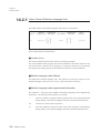
14.2.1 Output Format Of Machine Language Code .......................................292
14.2.2 Symbol Table .......................................................................................295
15.Using The Library Manager
15.1 Purpose Of This Chapter ...............................................................................298
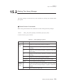
15.2 Starting The Library Manager ........................................................................299
MN10300 Cross Assembler
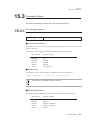
15.3 Command Options .........................................................................................301
15.3.1 Error Message Options........................................................................301
15.3.2 Program Generation Options...............................................................307
15.3.3 Functional Options...............................................................................309
15.3.4 Other Options ......................................................................................315
15.4 Error Messages .............................................................................................318
15.4.1 Warning Messages ..............................................................................319
15.4.2 Error Messages ...................................................................................320
15.4.3 Fatal Error Messages ..........................................................................322
16.Notes On The Operating Environment
16.1 Purpose Of This Chapter ...............................................................................324
16.2 Personal Computer Versions .........................................................................325
16.2.1 Purpose Of This Section......................................................................325
16.2.2 Operating Environment........................................................................325
16.2.3 Files .....................................................................................................326
16.2.4 Installation ...........................................................................................327
16.2.5 Environment Settings ..........................................................................328
16.2.6 Differences From The Workstation Versions .......................................330
16.2.7 Error Correction Using Tag Jumps.......................................................331
17.Appendix
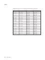
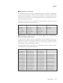
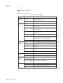
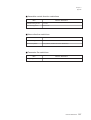
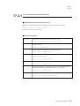
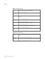
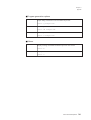
17.1 Numeric Restrictions......................................................................................336
17.2 List Of Command Options .............................................................................338
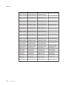
17.2.1 List Of Assembler Command Options .................................................339
17.2.2 List Of Linker Command Options ........................................................342
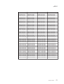
17.3 List Of Assembler Directives..........................................................................345
17.4 List Of Assembler Control Statements...........................................................348
Chapter 1
Getting Started
1.1 Purpose Of This Chapter ....................................................................................................2
1.2 Operating Environment ......................................................................................................3
1.3 File Organization ................................................................................................................4
1.4 Installation ..........................................................................................................................5
1.5 Setup...................................................................................................................................6
1.6 File Conversion Utility.....................................................................................................12
1
Chapter 1
Getting Started
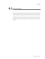
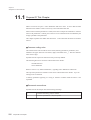
1.1
Purpose Of This Chapter
This Chapter describes the operating environment for this system and the usage of the file
conversion tool.
2
Purpose Of This Chapter
Chapter 1
Getting Started
1.2
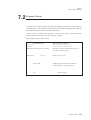
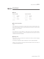
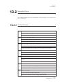
Operating Environment
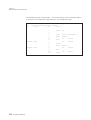
This system runs on the following workstations, personal computers, and compatibles.
Host machine
Operating system
Sun/Sparc
HP9000
PC-9801
PC/AT
SunOS
HP-UX
MS-DOS
MS-DOS, MS-DOS/V
For the PC/AT and compatibles, because of such differences as the ability to display
Japanese, this Manual indicates a machine running the English-only MS-DOS operating
system as a PC/AT and one running MS-DOS/V as a DOS/V machine.
Installing this system requires approximately 700 kilobytes of free disk space. Note that
this is just the space required for the files in the system distribution. Additional space is
required for development.
Operating Environment
3
Chapter 1
Getting Started
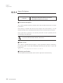
1.3
File Organization
The installation media for this system contain the following files.
as103 (assembler)
as103 is the assembler. For a description, see Chapter 5 "Using the Assembler."
ld103 (linker)
ld103 is the linker. For a description, see Chapter 6 "Using the Linker."
slib103 (library manager)
slib103 is the library manager, a utility for creating library files. For a description, see
Chapter 15 "Using the Library Manager."
excv103 (file conversion utility)
This utility converts an executable produced by the linker into a file in Motorola S format,
Intel HEX format, or Matsushita format.
In addition to the above files, the installation media may contain a README or
README.DOC file containing late-breaking news missing from this Manual. Please read
this file carefully before proceeding.
4
File Organization
Chapter 1
Getting Started
1.4
Installation
For the installation media, installation procedures, and notes on installation, see the
MN10300 Series PanaX Series Installation Manual.
Installation
5
Chapter 1
Getting Started
1.5
Setup
These procedures are for setting up this system when it has just been installed or for
altering basic settings.
■ Setting the command path
Unix uses the environment variable PATH when searching for executable files. Setting up
this variable properly allows users to omit the directory name for commands and run them
using their base names only.
If this system has been installed in /usr/local/bin, for example, adding the directory
/usr/local/bin to the PATH environment variable permits the use of the command name
only for the commands in this system.
Under Unix, most users initialize environment variables via a start-up file named .cshrc
and located in the user's home directory. If this is the case, use an editor to modify the
PATH variable setting in this start-up file.
To put the changes into effect, either log out and then log in again or use the source
command to execute the contents of .cshrc.
■ Start-up files
The assembler and linker start by reading start-up files which contain statements for
initializing start-up variables.
The assembler start-up file (.as103rc) contains statements specifying the following four
items.
(1) The default language and character coding scheme for messages from the assembler
(2) The character coding scheme for assembler source files
(3) The radix notation used for numbers
(4) The default toggle switch setting for optimization
The linker start-up file (.ld103rc) contains statements specifying the following six items.
(1) The language and character coding scheme for messages from the linker
(2) A toggle controlling output of debugging information to the executable file
(3) A toggle controlling output of the symbol table to the executable file
(4) A toggle controlling output of DATA sections to the executable file
(5) A toggle controlling output of a map file
(6) A toggle controlling output of an executable file when there are errors
6
Setup
Chapter 1
Getting Started
The assembler and linker search directories for these start-up files in the following order:
the current directory, the user's home directory, and the directory containing the
executable. If they find such a file, they use the contents to initialize their starting
parameters. Otherwise, they set the parameters to their default values. These default
values are given in the section "Start-up file format."
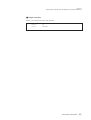
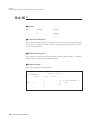
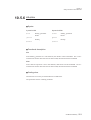
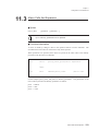
■ Start-up file format
The start-up files contain statements using the following format.
keyword
parameter
The first field is a keyword giving the name of the start-up parameter. The second field
specifies the value to assign to that parameter. The two fields must be separated by at least
one tab or space.
A sharp (#) may be used to incorporate comments into these start-up files. The assembler
and linker then ignore all text from the sharp through to the end of the line.
Each specification must end with a carriage return. In particular, make sure that
the last line ends with a carriage return. Some editors allow users to end the last
line with an end-of-file mark instead of a carriage return.
There is no way to specify multiple parameters on the same line.
Setup
Chapter 1
Getting Started
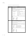
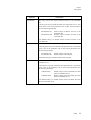
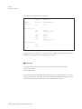
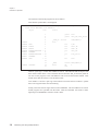
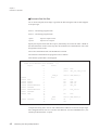
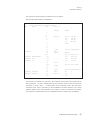
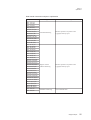
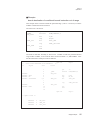
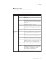
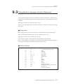
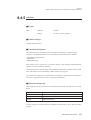
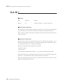
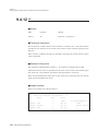
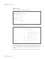
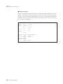
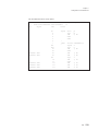
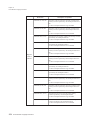
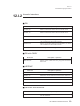
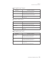
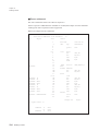
The start-up file .as103rc supports the following keywords.
keyword
message
Description
This entry specifies the language and coding scheme for messages
from the assembler.
Following the keyword message and separated from it with white
space is one of the parameters ENGLISH, EUC, SJIS, or JIS. These
parameters have the following meanings.
message ENGLISH
Outputs messages in English
message EUC
Outputs messages in Japanese using
EUC encoding
message SJIS
Outputs messages in Japanese using
Shift JIS encoding
message JIS
Outputs messages in Japanese using JIS
encoding
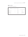
The default setting depends on the host machine and operating
system.
Sun/Sparc
HP9000
PC-9801
DOS/V
PC/AT
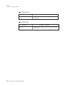
file
ENGLISH
ENGLISH
SJIS
SJIS
ENGLISH
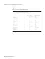
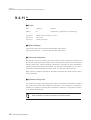
This entry configures the assembler to accept source files containing
Japanese text by specifying the coding scheme used.
Note: Errors may result if the specification does not match the
coding scheme used in the file.
Following the keyword file and separated from it with white space is
one of the parameters ASCII, EUC, SJIS, or JIS. These parameters
have the following meanings.
file ASCII
file EUC
file SJIS
file JIS
Process input as ASCII code
Process input as EUC code
Process input as Shift JIS code
Process input as JIS code
The default setting depends on the host machine and operating
system.
Sun/Sparc
HP9000
PC-9800
DOS/V
PC/AT
8
Setup
EUC
SJIS
SJIS
SJIS
ASCII
Chapter 1
Getting Started
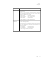
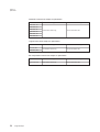
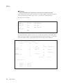
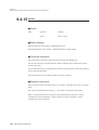
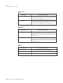
keyword
notation
Description
This entry specifies the notation used for numbers in assembly
language programs.
Following the keyword notation and separated from it with white
space is one of the parameters PANA, CLANG, or INTEL. These
parameters have the following meanings.
notation PANA
notation CLANG
notation INTEL
Use Panasonic notation
Use C language notation
Use Intel notation
The default setting is in extended C language format.
O-OPTION
This entry controls optimization.
Following the keyword O-OPTION and separated from it with white
space is one of the parameters ON or OFF. These parameters have
the following meanings.
O-OPTION ON
O-OPTION OFF
Enable optimization
Disable optimization
The default setting is to disable optimization.
Setup
9
Chapter 1
Getting Started
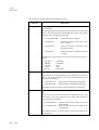
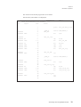
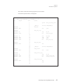
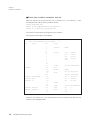
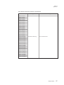
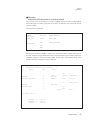
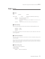
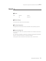
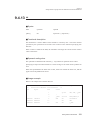
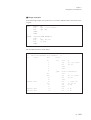
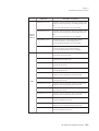
The start-up file .ld103rc supports the following keywords.
keyword
message
Description
This entry specifies the language and coding scheme for messages
from the linker.
Following the keyword message and separated from it with white
space is one of the parameters ENGLISH, EUC, SJIS, or JIS. These
parameters have the following meanings.
message ENGLISH
Outputs messages in English
message EUC
Outputs messages in Japanese using
EUC encoding
message SJIS
Outputs messages in Japanese using
Shift JIS encoding
message JIS
Outputs messages in Japanese using JIS
encoding
The default setting depends on the host machine and operating
system.
Sun/Sparc
HP9000
PC-9801
DOS/V
PC/AT
g-OPTION
ENGLISH
ENGLISH
SJIS
SJIS
ENGLISH
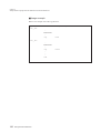
This entry controls the output of debugging information.
Following the keyword g-OPTION and separated from it with white
space is one of the parameters ON or OFF. These parameters have
the following meanings.
g-OPTION ON
g-OPTION OFF
Enable output of debugging information
Disable output of debugging information
The default setting is to disable output of debugging information.
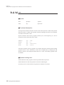
En-OPTION
This entry controls the output of the symbol table to the executable
file.
Following the keyword En-OPTION and separated from it with
white space is one of the parameters ON or OFF. These parameters
have the following meanings.
En-OPTION ON
En-OPTION OFF
Disable output of the symbol table to the
executable file
Enable output of the symbol table to the
executable file
The default setting is to disable output of the symbol table to the
executable file.
10
Setup
Chapter 1
Getting Started
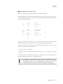
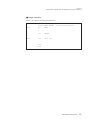
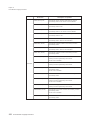
keyword
Ed-OPTION
Description
This entry controls the output of DATA sections to the executable
file.
Following the keyword Ed-OPTION and separated from it with
white space is one of the parameters ON or OFF. These parameters
have the following meanings.
Ed-OPTION ON
Ed-OPTION OFF
Enable output of DATA sections to the
executable file
Disable output of DATA sections to the
executable file
The default setting is to disable output of DATA sections to the
executable file.
m-OPTION
This entry controls the output of the map file.
Following the keyword m-OPTION and separated from it with white
space is one of the parameters ON or OFF. These parameters have
the following meanings.
m-OPTION ON
m-OPTION OFF
Enable output of the map file
Disable output of the map file
The default setting is to disable output of the map file.
r-OPTION
This entry controls the output of the executable file when there are
assembler errors.
Following the keyword r-OPTION and separated from it with white
space is one of the parameters ON or OFF. These parameters have
the following meanings.
r-OPTION ON
r-OPTION OFF
Enable output of the executable file when
there are assembler errors
Disable output of the executable file when
there are assembler errors
The default setting is to disable output of the executable file when
there are assembler errors.
Setup
11
Chapter 1
Getting Started
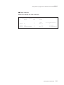
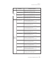
1.6
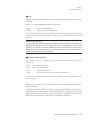
File Conversion Utility
This file conversion utility converts an executable produced by the linker into a file in
Intel HEX format, or Motorola S format.
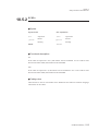
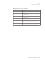
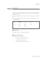
■ General command format
The general command format used to start the file conversion utility is shown below.
excv103 [options] EX format file name
Contents of brackets [ ] may be omitted.
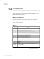
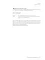
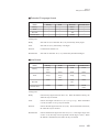
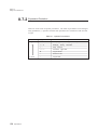
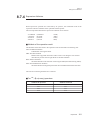
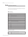
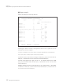
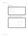
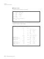
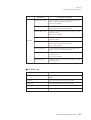
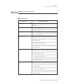
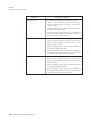
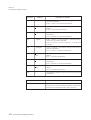
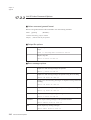
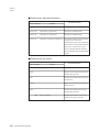
■ Options
Option
Function
–j
Display errors and warning messages in Japanese. *1
–e
Display errors and warning messages in English. *2
–h
Display help information regarding file conversion utility options.
–W
Perform conversion using a work file during execution. This enables a large
amount of data to be converted even if the personal computer has little memory.
However, the conversion is performed at slower speed.
–i
Output the execution file in Intel HEX format.
–S3
Output the execution file in Motorola S3 format.
–S2
Output the execution file in Motorola S2 format.
–S1
Output the execution file in Motorola S1 format.
–ofile
Specify the file name to be output.
-p
No padding.
-P
Padding.
-R start address
If omitting the end address, a conversion is performed until the last address of
[, last address]
the execution module.
-A start address
Convert the start address of the EX file to the specified address.
*1: Option for UNIX version
*2: Option for DOS/V and PC9800 version
12
File Conversion Utility
Chapter 1
Getting Started
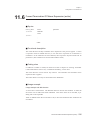
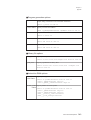
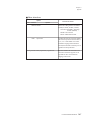
■ Default settings
In the absence of the -i, -S3, -S2 or -S1 options, the output format defaults to the Motorola
S3 format.
In the absence of the -o option, the output file has the name of the executable file with the
extension .sf added and is located in the same directory as the executable file.
In the absence of the -p or -P options, padding is not supressed in the output file.
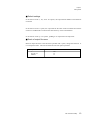
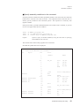
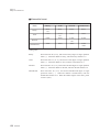
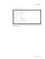
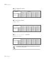
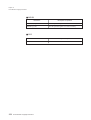
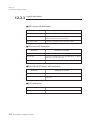
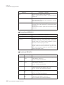
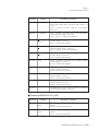
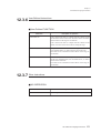
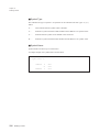
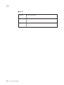
■ Ruels of output file name
Based on input file name or the file name specified with o option, change the extension. It
is an output file name. The rules are diferent from each option specified.
option
i
S3, S2, S1
default
extension
.hex
.sf
.sf
File Conversion Utility
13
Chapter 1
Getting Started
14
File Conversion Utility
Chapter 2
Program Development Flow
2.1 Purpose Of This Chapter ..................................................................................................16
2.2 Program Development Flow ............................................................................................17
2.3 Programming With The Assembler..................................................................................19
2
Chapter 2
Program Development Flow
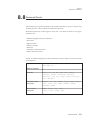
2.1
Purpose Of This Chapter
Programs can be developed with a compiler or an assembler.
Currently most program development is done with a compiler, but an assembler is where
compact code generation or faster processing speed is required.
This Chapter describes the procedures for developing in assembly language.
16
Purpose Of This Chapter
Chapter 2
Program Development Flow
2.2
Program Development Flow
■ Main development flow
MN10300 series microcomputers are used in such diverse applications as AV equipment,
household electronics, information equipment, automobiles, robots, portable phones,
computer peripherals, etc. Programs developed with the MN10300 Series CrossAssembler are ultimately incorporated into these products.
The software is developed using a source code debugger running the software on a target
board which differs from the operating environment for the final application.
■ Assembler and compiler
Both the assembler and C compiler can be used to develop programs for MN10300 series
microcomputers. Compared to assembly language, C language is a more productive
language. Programs coded using a high-level language also offer superior documentabirity.
On the other hand, microcomputer operations can be directly coded by programming with
assembly language. Compared to high-level languages, programs can be created with more
compact code size, less redundancy, and faster processing.
Given the features of both languages, the main body of a program can be coded using C
language, while parts that require fast processing can be coded using assembly language.
When developing a program, the programmer must first consider which language to use,
program structure, processing speed required to meet the target performance of the end
product, ROM size of the device, and several other related factors.
■ Source code debugger
The software developed on a workstation or personal computer must be checked using a
hardware environment similar to that used by the final product.
Nearly all MN10300 series microcomputers will ultimately be incorporated within end
products. Therefore, program debugging must also be performed under the same
conditions as the end product. This is why a source code debugger and in-circuit emulator
are provided.
Program Development Flow
17
Chapter 2
Program Development Flow
The probe of the in-circuit emulator can operate in place of the microcomputer by
connecting it through the microcomputer socket in the product.
The source code debugger is a program for controlling the in-circuit emulator's hardware.
The debugger downloads the application developed on a workstation or personal
computer to the emulator's memory to create an environment in which the application runs
as if it were in the microcomputer's ROM. It can start program execution as the address of
any source statement, and can temporarily stop execution. Also, when execution is
stopped, the source code debugger can display values of internal registers and memory
and can be used to verify desired operation of programs by changing those values. It also
enables more detailed operation checks with step operation, whereby execution proceeds
one instruction at a time.
Using this development environment, the developer can prove programs in the same state
as when finally incorporated into the microprocessor.
18
Program Development Flow
Chapter 2
Program Development Flow
2.3
Programming With The Assembler
Before creating programs using the assembler, you must understand the following items.
■ Required knowledge
• MN10300 series machine-language instructions
• MN10300 series device operation
• Editor use
• C compiler use
• Assembler and linker use (in this manual)
• Debugger use
Program development is an iterative process of editing, assembling, linking, and debugging
many times until finished. Therefore, you should as much as possible automate assembler
and linker commands, debugger calls, and error correction.
■ MAKE
When a program is divided into multiple files for joint development efforts by several
programmers, a control system must be created for assembly and linking without error.
If this is not done, then an old undebugged program could be linked within the iterative
development process.
The solution lies with the following program which runs on the workstation or personal
computer.
• MAKE
With MAKE the programmer defines the dependency relationships of the files needed to
generate the final executable file and list files. Afterwards MAKE will automatically
assemble and link only those files that have been modified.
Programming With The Assembler
19
Chapter 2
Program Development Flow
■ Program format
The MN10300 Series Cross-Assembler utilizes a program format called section address
format.
Section address format specifies the start addresses of programs for each section linked.
Even when the program is divided between multiple files, or when a file is divided into
multiple sections, identical sections are linked together with the same attributes.
Therefore, the programmer must create programs such that addresses do not overlap.
Refer to chapter 6, "Using The Linker", for details.
■ Programming style
It is important to use a consistent style for program coding from start to finish. When
several people are to create a program, they should meet in advance to decide on a
common style.
You should consider the following points regarding the fixed style of the MN10300 Series
Cross-Assembler.
• Header files
Constants and variables used in all files and define identifiers used in common should
be gathered into a single header file. As a result, changes can be made at just one
location in the header file.
• Library files
Subroutine programs frequently used by different files should be gathered by function
as library files to make programs easier to use.
• Declaration position global directives
Use one position for global directive declarations. The global directive can be declared
anywhere within a program, but confusion will result if the declaration positions differ
across source files.
• Unify radix and notation directives
Choose a common default radix for coding numbers, constant values, strings, etc.
• Comment statements
Comments reveal program algorithms and processing details within a program. Choose
a common format for coding comment statements.
20
Programming With The Assembler
Chapter 2
Program Development Flow
■ Optimization
This Series' optimizations apply to unconditional branches, data transfer instructions,
arithmetic instructions, logical instructions, bit manipulation instructions, and user-defined
instructions.
• Unconditional branches that undergo optimization
• Data transfer, arithmetic, logical, bit manipulation, and user-defined instructions that
undergo optimization
Coding is not a simple task if the programmer must always select the optimal instruction
from the above instructions. In particular, it is nearly impossible to select the optimal
instructions when coding a program divided between files in section format.
The optimization functions provide a solution to these problems. The assembler and linker
use them to produce the optimal code no matter what the source code.
The assembler evaluates the source statement notation. It evaluates the immediate data,
memory specifications, and displacement data appearing as operands to a data transfer,
arithmetic, logical, bit manipulation, and user-defined instructions and selects the shortest
version of the instruction.
The assembler also examines unconditional branches, choosing the shortest versions for the
CALL, CALLS, JMP, and JSR instructions.
The linker evaluates instructions that were the object of optimization, and selects the
optimal codes.
As a result, the programmer must be aware that the generated code will differ from the
source statements coded in the list file.
Refer to chapter 4, "Optimization", for details.
Programming With The Assembler
21
Chapter 2
Program Development Flow
■ Conditional assembly
If a program for product A is to be created by partially modifying a program for product B, then
both can be combined into a single program by using conditional assembler control instructions.
Conditional assembly is done by defining a single symbol at the start of the program using
a define control directive.
Here is an example.
#define
TYPE
A
Using TYPE and conditional assembler control directives to process different parts of the
program, the programmer writes code in the format below.
.
.
.
#ifdef
TYPE
Program of product A
#else
Program of product B
#endif
.
.
.
TYPE has been defined with define, so in this case the program for product A will be
assembled. If the statement
#define
TYPE
A
is omitted, then the program for product B will be assembled.
By using conditional assembler control directives in this manner, different versions of
programs can be managed in a single source file.
Refer to chapter 10, "Writing Assembler Control Statements", for details.
22
Programming With The Assembler
Chapter 2
Program Development Flow
■ Macros
Macros are an important function of the assembler. A macro assigns a name to a process,
thereby simplifying the coding of that process. By assigning an appropriate macro name to
a block of multiple machine language instructions, the programmer can create custom
instructions.
■ Debugging
When performing final program debugging, the programmer must verify whether the
intended operations are being performed or not. A source code debugger is provided for
this. The programmer uses the debugger to download generated and linked object code and
then verify operation.
The g option of the assembler and linker generates information that allows the debugger to
work with symbols. This allows symbols to be used for specifying debugger start
addresses, breakpoint settings, memory references and changes, etc.
Programming With The Assembler
23
Chapter 2
Program Development Flow
24
Chapter 3
Introduction To Operation
3.1 Purpose Of This Chapter ..................................................................................................26
3.2 Files Used By Assembler And Linker..............................................................................27
3.3 Basic Operation Of Assembler and Linker ......................................................................29
3.4 Assembling And Linking Multiple Sections ....................................................................35
3.5 Conditional Assembly And Linking.................................................................................45
3
Chapter 3
Introduction To Operation
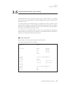
3.1
Purpose Of This Chapter
Many options are provided with the MN10300 Series Cross-Assembler, but you can use
the assembler and linker without knowing all of them. This chapter explains how to use
the most useful options while demonstrating actual operation.
This chapter first uses an example to show how to run the assembler and linker. Next, it
explains assembler and linker use when assembler control statements and macro
instructions are included for high-level operations.
After reading this chapter once through and trying actual operation, you will have
mastered basic assembler and linker operation.
26
Purpose Of This Chapter
Chapter 3
Introduction To Operation
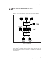
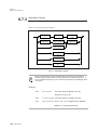
3.2
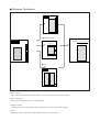
Files Used By The Assembler And Linker
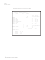
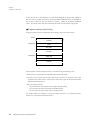
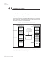
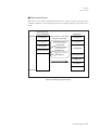
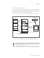
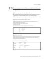
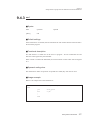
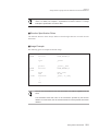
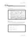
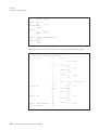
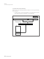
Figure 3-1 shows the inter-relationships of the files used by the assembler and linker.
Map file
Source file
Include file
List file
Assembler
Library file
Relocatable object files
Linker
Map file
Executable file
Figure 3-1 : Files Used
The assembler inputs source files and include files, and outputs relocatable object files.
Include files are not special files, but are just files that comprise parts of the source file.
They are incorporated into assembly at the location of include directives defined within
source statements.
Files Used By Assembler And Linker
27
Chapter 3
Introduction To Operation
Depending on the option specifications input for the source file and map file, a list file
will be output with fully resolved addresses.
The map file is used to output a list file with fully resolved addresses.
The linker inputs relocatable object files output by the assembler and, depending on
option specifications, library files. It generates an executable format file and, depending
on option specifications, a map file.
Library files are collections of relocatable object files of frequently used programs and
hardware interface programs. Only needed modules are specified to have the linker
extract the appropriate relocatable object files from library files and load them into the
executable format file. Several library files are provided, but you can maintain them or
newly create them yourself. Refer to chapter 15, "Using The Library Manager", for
details.
You cannot force different extensions for map files and list files. You can only specify
whether or not to output these files. However, the extensions of relocatable object files
and the executable format file can be changed with assembler and linker option
specifications. In this case, the file specification must include the extension.
28
Files Used By Assembler And Linker
Chapter 3
Introduction To Operation
3.3
Basic Operation Of The Assembler And Linker
The MN10300 Series Cross-Assembler uses a section address format, in which the start
address for each section as defined with the section directive corresponds to its start
address when linked. This allows the programmer to freely change the order of linking
files.
The following explanation illustrates a simple example of only one section. In this
example you will assemble and link two source files, program1.asm and program2.asm.
These two files have related external references and external definitions, where the
subroutine of program2.asm is called from program1.asm. Therefore the final list files
cannot be created just by assembling program1.asm. In this example, you will generate
with the linker a map file and then generate the final list files.
■ Create source files
First, create the source files. Using an editor, create the two programs shown below
(program1.asm and program2.asm).
The contents of program1.asm are as follows.
_CODE
main
_DATA
data1
global
data_set
section
CODE,PUBLIC,1
mov
mov
mov
jsr
bra
0,A0
0xff ,D0
0x80 ,D1
data_set
main
section
ds
end
DATA,PUBLIC,4
4
program1.asm consists of a section called _CODE (attribute CODE, link type PUBLIC)
and a section called _DATA (attribute DATA, link type PUBLIC).
Basic Operation Of Assembler And Linker
29
Chapter 3
Introduction To Operation
The contents of program2.asm are as follows.
_CODE
data_set
global
data_set
section
CODE,PUBLIC,1
mov
0,D2
cmp
bcc
D1,D2
data_set_end
mov
add
add
bra
D0,(A0)
1,D2
2,A0
data_set_loop
data_set_loop
data_set_end
rts
end
program2.asm also consists of a section called _CODE (attribute CODE, link type
PUBLIC), and it makes an external declaration of data_set.
■ Assemble
Assemble the two programs that you created to generate relocatable object files.
as103 program1.asm
as103 program2.asm
This will generate two relocatable object files (program1.rf and program2.rf). List files
cannot be generated at this stage. These files will be generated after linking when the
relationships of external references and external definitions are resolved.
30
Basic Operation Of Assembler And Linker
Chapter 3
Introduction To Operation
■ Link
Link the two relocatable object files to create an executable file. At the same time, generate
a map file.
ld103 -m -T_CODE=40000000 program1.rf program2.rf
m option
T option
Option to output map file.
Option to specify section address.
The above command line links two relocatable object files (program1.rf and program2.rf)
and creates an executable file (m103.ex) and a map file (m103.map) in the current
directory.
Supplemental Explanation
The -o option is also available for specifying a different output file name and directory for the
executable file. Omitting this option results in the use of the default name m103 and the
extension .ex. There is no option for specifying the name of the map file. It uses the same
default name as the executable file, m103, and the extension .map. The output directory is
the same as that used for the executable file.
■ Generate final list files
After link processing is complete, generate the final list files using the map file
(m103.map).
as103 -l -a m103.map program1.asm
as103 -l -a m103.map program2.asm
l option
Option to output a list file.
a option
Option to read a map file. Specify the map file name after it.
This operation will generate the final list files (program1.lst and program2.lst) in the
current directory.
With the above operations, you can generate an executable format file and final list files in
the current directory.
You must generate the final list files using the map file after linking. This is because
linking determines the start addresses of sections following the T option for files in section
address format. Also note that there are lines for which it is impossible to determine the
address until after optimization. (See Chapter 4 "Optimization Functions.")
Basic Operation Of Assembler And Linker
31
Chapter 3
Introduction To Operation
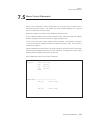
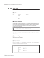
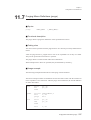
The contents of the final list file program1.lst are as follows.
program1.lst
***
PanaX Series MN103000 Cross Assembler
Loc
Object
Line
Page 1
***
Source
1
global
data_set
2
40000000
3
_CODE
4
main
section CODE,PUBLIC,1
40000000
9000
5
mov
0,A0
40000002
2CFF00
6
mov
0xff ,D0
40000005
2D8000
7
mov
0x80 ,D1
40000008
F8FEFCFCFF0C0000
8
jsr
data_set
40000010
00F8FE04
8
40000014
CAF2
bra
main
9
10
40000024
00000000
11
_DATA
section DATA,PUBLIC,4
12
data1
ds
13
end
program1.lst
*** Symbol Table ***
32
40000016
T
data_set
40000000
T
main
40000024
D
data1
Basic Operation Of Assembler And Linker
4
Page 2
Chapter 3
Introduction To Operation
The contents of the final list file (program2.lst) are as follows.
program2.lst
***
PanaX Series MN103000 Cross Assembler
Loc
Object
Line
Page 1
***
Source
1
global
data_set
2
40000016
40000016
8A00
3
_CODE
4
data_set
5
section CODE,PUBLIC,1
mov
0,D2
6
40000018
7
data_set_loop
40000018
A6
8
cmp
D1,D2
40000019
C60A
9
bcc
data_set_end
4000001b
60
11
mov
D0,(A0)
4000001c
2A01
12
add
1,D2
4000001e
2002
13
add
2,A0
40000020
CAF8
14
bra
data_set_loop
10
15
40000022
40000022
16
F0FC
data_set_end
17
rts
18
end
program2.lst
Page 2
*** Symbol Table ***
40000016
T
data_set
40000018
T
data_set_loop
40000022
T
data_set_end
Here is a simple explanation of how to read the list files. A list file shows two items of
information.
• Source statements and machine language code
• Symbol table
Source statements and their corresponding machine language code are further divided into
Loc, Object, Line, and Source headings.
Basic Operation Of Assembler And Linker
33
Chapter 3
Introduction To Operation
The Loc heading gives location counter values, which show execution addresses in the
final list files. program1.lst starts from location 40000000 (hex.), and program2.lst starts
from location 40000016 (hex.).
The Object heading shows the codes of instructions converted to machine language by the
assembler. Instructions consist of one to seven bytes (1 byte=8 bits), shown as two to
eight hex digits. After some machine language code, the symbol 'M' will be added. The
'M' indicates an instruction that was expanded from a macro instruction.
The Line heading shows line numbers added by the assembler. The Source heading
shows the source statements as coded.
34
Basic Operation Of Assembler And Linker
Chapter 3
Introduction To Operation
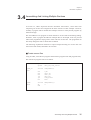
3.4
Assembling And Linking Multiple Sections
In section 3.3, "Basic Operation Of The Assembler And Linker", source files each
comprising one section were assigned to the same section as a basic example. However,
normally a program will be divided into multiple sections to clearly divide programs by
function and type.
The start addresses of a program in section format are set for each section during linking.
Therefore, when a program divided into multiple files is developed, work can proceed
without the programmer staying aware of the code size of each file. The programmer an
also freely change the order in which files are linked.
The following explanation illustrates a simple example dividing two source files into
sections for each routine, allocated to two sections.
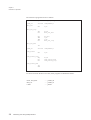
■ Create source files
Using an editor, create the two programs shown below (program3.asm and program4.asm).
The contents of program3.asm are as follows.
_CODE_00
main
_DATA
data1
global
global
main
data_set,time_filler
section
CODE,PUBLIC,1
mov
mov
mov
jsr
jsr
bra
0,A0
0xff ,D0
0x80 ,D1
data_set
time_filler
main
section
ds
end
DATA,PUBLIC,4
4
Assembling And Linking Multiple Sections
35
Chapter 3
Introduction To Operation
The contents of program4.asm are as follows.
_CODE_01
data_set
global
data_set,time_filler
section
CODE,PUBLIC,1
mov
0,D2
cmp
bcc
D1,D2
data_set_end
mov
add
add
bra
D0,(A0)
1,D2
2,A0
data_set_loop
data_set_loop
data_set_end
rts
_CODE_00
section
CODE,PUBLIC,1
mov
0,D2
time_filler
time_filler_loop
cmp
bcc
bra
D1,D0
time_filler_end
time_filler_loop
time_filler_end
rts
end
As can be seen from the above two files, these programs are divided as follows.
• main, time_filler
• data_set
• data1
36
Assembling And Linking Multiple Sections
......_CODE_00
......_CODE_01
......_DATA
Chapter 3
Introduction To Operation
■ Assemble and generate list files
Next assemble the two programs. Assemble with the option for output of list files in order
to see what the list file is like when final addresses are not resolved.
as103 -l -g program3.asm
as103 -l -g program4.asm
g option
Option to output debug information in the relocatable object file.
l option
Option to output list file (not normally specified at this stage before linking, but
specify it here to see intermediate values).
This will assemble the two source files (program3.asm and program4.asm) in the current
directory. It will add debug information (g option) to the relocatable object files
(program3.rf and program4.rf), and generate list files (program3.lst and program4.lst)
respectively in the current directory (l option). Adding debug information (g option)
enables symbols to be used during debugging.
Let's take a look at the list files that were created.
Assembling And Linking Multiple Sections
37
Chapter 3
Introduction To Operation
The contents of the list file program3.lst are as follows.
Note that the symbol table is not displayed.
program3.lst
***
PanaX Series MN103000 Cross Assembler
Loc
Object
Line
Page 1
***
Source
1
global
main
2
global
data_set,time_filler
3
00000000
4
_CODE_00
5
main
section
CODE,PUBLIC,1
00000000
9000
6
mov
0,A0
00000002
2CFF00
7
mov
0xff ,D0
00000005
2D8000
8
mov
0x80 ,D1
00000008
F8FEFCFCFF000000
+ 9
jsr
data_set
00000010
00F8FE04
00000014
F8FEFCFCFF000000
jsr
time_filler
0000001c
00F8FE04
00000020
CA00
bra
main
9
+ 10
10
+ 11
12
00000000
00000000
13
_DATA
section DATA,PUBLIC,4
14
data1
ds
15
4
end
There is a plus sign '+' before line numbers 9 and 10. This indicates that the object code
does not have final values. This is because the two functions data_set and time_filler do
not exist in this program, so the call addresses will not be resolved unless linked. That
further means that this list file is not the final list file.
Line number 11 also has a plus sign. This indicator warns that the line contains a symbol
that is not assigned a final value until linking.
Finally, notice that the list begins from location 00000000. The start addresses of section
format programs are specified with the linker. Here the assembler uses relative values
beginning from 00000000 as location counter values.
38
Assembling And Linking Multiple Sections
Chapter 3
Introduction To Operation
The contents of the list file program4.lst are as follows.
Note that the symbol table is not displayed.
program4.lst
***
PanaX Series MN103000 Cross Assembler
Loc
Object
Line
Page 1
***
Source
1
global
data_set,time_filler
2
00000000
00000000
8A00
3
_CODE_01
4
data_set
5
section CODE,PUBLIC,1
mov
0,D2
8
cmp
D1,D2
+ 9
bcc
data_set_end
6
00000002
7
data_set_loop
00000002
A6
00000003
C600
00000005
60
11
mov
D0,(A0)
00000006
2A01
12
add
1,D2
00000008
2002
13
add
2,A0
0000000a
CA00
+ 14
bra
data_set_loop
10
15
0000000c
0000000c
16
F0FC
data_set_end
17
rts
18
19
_CODE_00
section CODE,PUBLIC,1
20
00000000
00000000
21
8A00
time_filler
22
mov
0,D2
23
00000002
24
00000002
A4
00000003
00000005
time_filler_loop
25
cmp
D1,D0
C600
+ 26
bcc
time_filler_end
CA00
+ 27
bra
time_filler_loop
28
00000007
00000007
29
F0FC
time_filler_end
30
rts
31
end
32
Assembling And Linking Multiple Sections
39
Chapter 3
Introduction To Operation
This file is defined as two sections. The addresses of the starting locations of both
sections is assumed 00000000.
The plus signs in lines 14 and 27 have the same meaning that they had in program3.lst-namely, that the line contains a symbol that is not assigned a final value until linking.
■ Link
Link the two relocatable object files to generate an executable format file. Specify the
g option to add debug information to the executable format file.
ld103 -m -g -T_CODE_00=80000000 -T_CODE_01=80005000 program3.rf program4.rf
m option
Option to output map file.
g option
Option to add debug information to the executable format file.
T option
Option to specify section address.
The above command line links two relocatable object files (program3.rf and program4.rf)
in the current directory, assigning the starting address 80000000 (hex.) to section
_CODE_00 and the starting address 80005000 (hex.) to section _CODE_01, and creates
an executable file (m103.ex) including debugging information and a map file (m103.map)
in the current directory.
40
Assembling And Linking Multiple Sections
Chapter 3
Introduction To Operation
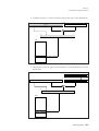
■ Parameter file during linking
The following command was input to link.
ld103 -m -g -T_CODE_00=80000000 -T_CODE_01=80005000 program3.rf program4.rf
Repeated input of lines like this is tedious and prone to errors. For this reason the very
convenient @ option is provided with the linker. With an editor create a file pfile (the
name can be freely chosen) with the following contents.
The contents of pfile are as follows.
-m
-g
-T_CODE_00=80000000
-T_CODE_01=80005000
program3.rf program4.rf
This file is called a parameter file. If the @ option is specified when linking, then the
linker will read a parameter file, and will interpret its contents as command options for
execution.
The two specifications below will be equivalent.
ld103 @pfile
ld103 -m -g -T_CODE_00=80000000 -T_CODE_01=80005000 program3.rf program4.rf
Assembling And Linking Multiple Sections
41
Chapter 3
Introduction To Operation
■ Generate final list files
Let us use the map file (m103.map) to generate the final listing file and see what happens
to the plus signs.
as103 -l -a m103.map program3.asm
as103 -l -a m103.map program4.asm
l option
Option to output a list file.
a option
Option to use a map file.
Specify the map file name after the a option, followed by the source file name. Based on
the link information written in the map file, the assembler will reassemble the source file
and generate a final list file.
Let's look at the final list files with all addresses resolved.
The contents of the final list file program3.lst are as follows.
Note that the symbol table is not displayed.
program3.lst
***
PanaX Series MN103000 Cross Assembler
Loc
Object
Line
Page 1
***
Source
1
global
main
2
global
data_set,time_filler
3
80000000
4
_CODE_00
5
main
section CODE,PUBLIC,1
80000000
9000
6
mov
0,A0
80000002
2CFF00
7
mov
0xff ,D0
80000005
2D8000
8
mov
0x80 ,D1
80000008
F8FEFCFCFFF44F00
9
jsr
data_set
80000010
00F8FE04
9
80000014
F8FEFCFCFF0C0000
10
jsr
time_filler
8000001c
00F8FE04
10
80000020
CAE0
11
bra
main
12
8000500e
00000000
13
_DATA
14
data1
15
section DATA,PUBLIC,4
ds
4
end
Compare this listing file to the one with indeterminate addresses. Note how the plus signs
have disappeared from lines 9-11 and how the addresses start from 80000000 (hex.), the
number specified with the -T option.
42
Assembling And Linking Multiple Sections
Chapter 3
Introduction To Operation
The contents of the final list file (program4.lst) are as follows.
Note that the symbol table is not displayed.
program4.lst
***
PanaX Series MN103000 Cross Assembler
Loc
Object
Line
Page 1
***
Source
1
global
data_set,time_filler
2
80005000
80005000
8A00
3
_CODE_01
4
data_set
section CODE,PUBLIC,1
5
mov
0,D2
8
cmp
D1,D2
9
bcc
data_set_end
6
80005002
7
80005002
A6
80005003
C60A
data_set_loop
10
80005005
60
11
mov
D0,(A0)
80005006
2A01
12
add
1,D2
80005008
2002
13
add
2,A0
8000500a
CAF8
14
bra
data_set_loop
15
8000500c
8000500c
16
F0FC
data_set_end
17
rts
18
19
_CODE_00
section CODE,PUBLIC,1
20
80000022
80000022
21
8A00
time_filler
22
mov
0,D2
23
80000024
24
time_filler_loop
80000024
A4
25
cmp
D1,D0
80000025
C605
26
bcc
time_filler_end
80000027
CA03
27
bra
time_filler_loop
28
8000002a
8000002a
29
F0FC
time_filler_end
30
rts
31
end
32
Assembling And Linking Multiple Sections
43
Chapter 3
Introduction To Operation
In this file the ' ' on line numbers 14 and 27 have disappeared, and the start address of
the first section _CODE_01 has been changed to address 80005000 (hex.) as specified by
the T option. However, the start address of section _CODE_00 is address 80000022
(hex.). This shows that it has been linked after the same section existing in program3.
■ Program locations after linking
Program locations in the executable file after linking as above are shown below.
0X0000
==
0X80000000
Unused
==
main
time_filler
==
0X80005000
Unused
==
data_set
data1
==
Unused
==
If the program contains multiple sections, it is laid out using the following rules.
• Each section is assigned the starting address specified to the linker.
• Sections with the same section name and section attributes are merged in the order
specified to the linker--that is, in the order in which they appear in the object file names
following the linker options.
• Rules for joining sections
1. Join in the order in which the sections appear during linking.
2. Join sections for which both name and attribute match.
3. Join sections for which either name or attribute match.
For further details, see Chapter 6 "Using the Linker" Section 6.3 "Command Options"
Section 6.3.3 "Program Generation Options."
44
Assembling And Linking Multiple Sections
Chapter 3
Introduction To Operation
3.5
Conditional Assembly And Linking
The MN10300 Series Cross-Assembler provides many assembler directives. Assembler
directives are not converted directly to machine language, but are used to control how the
assembler processes.
For example, during the development stage a programmer may want to include a special
program only for debugging. This program must be deleted when the product is complete.
That can be accomplished by editing the source file, but if that editing is spread throughout
the program, then mistakes will be easy to make.
It is convenient to use assembler directives in such cases. The conditions for assembly are
defined at the start of the program, and programs to be assembled when the conditions are
satisfied or not satisfied are written in the source file.
■ Create source file
Using an editor, create the program program5.asm shown below.
The contents of program5.asm are as follows.
#define
DEBUG
dat_set
macro
mov
mov
mov
endm
_CODE
main
#ifdef
section CODE,PUBLIC,2
adr,dat
adr,A0
dat,D0
D0,(A0)
DEBUG
dat_set
data1,0x11
dat_set
data1,0x22
#else
#endif
_DATA
data1
data2
section DATA,PUBLIC,2
dw
0
dw
0
end
Conditional Assembly And Linking
45
Chapter 3
Introduction To Operation
The operation of this program is meaningless. The program will be used instead to
explain program structure as it pertains to conditional assembly.The define DEBUG on the
first line selects DEBUG as a condition by defining the identifier DEBUG. In the
assembly control block starting with #ifdef DEBUG on line 13, the instructions between
#ifdef to #else will be assembled if DEBUG has been defined, and the instructions
between #else to #endif will be assembled if DEBUG is undefined. In this example
DEBUG was defined on line 1, so the instructions in the defined block will be assembled.
This program also uses a macro control directive. Lines 4 to 8 are the macro definition.
The macro's name is dat_set, and it has two parameters (adr, dat).
■ Assemble and link
Assemble and link the program that you have created.
as103 program5.asm
ld103 -m -T_CODE=40000000 program5.rf
as103 -l -a m103.map program5.asm
The first assembly generates the relocatable object file program5.rf. The second assembly
generates the final list file program5.lst.
Let's look at the contents of the list file that was generated.
46
Conditional Assembly And Linking
Chapter 3
Introduction To Operation
The contents of the final list file (program5.lst) are as follows.
Note that the symbol table is not displayed.
program5.lst
***
PanaX Series MN103000 Cross Assembler
Loc
Object
Line
1
Page 1
***
Source
#define
DEBUG
dat_set
2
3
M 4
macro
adr,dat
5
mov
adr,A0
6
mov
dat,D0
7
mov
D0,(A0)
8
endm
9
10
40000000
11
_CODE
12
main
13
#ifdef
M 14
section CODE,PUBLIC,1
DEBUG
dat_set data1,0x11
40000000
FCDC0C000040
14+
mov
data1,A0
40000006
8011
14+
mov
0x11,D0
40000008
60
14+
mov
D0,(A0)
15
#else
16X
17
dat_set data1,0x22
#endif
18
19
_DATA
section DATA,PUBLIC,4
4000000C
00000000
20
data1
dd
0
40000010
00000000
21
data2
dd
0
22
end
Line number 14 extends over four lines. This indicates lines where macro expansion has
been performed. An 'M' is added before the line number where the macro instruction
statement is shown, and a '+' is added after the line numbers where the instruction
statements from macro expansion are shown.DEBUG has been defined, so the block
between #ifdef to #else was assembled. Line number 16 has an X after the line number.
This indicates a statement that was not assembled because a condition was not fulfilled.
Conditional Assembly And Linking
47
Chapter 3
Introduction To Operation
■ Select false condition, assemble, and link
Make the define source statement line into a comment line, or just delete it. Then
assemble and link with the same procedure as before.
as103 program5.asm
ld103 -m -T_CODE=40000000 program5.rf
as103 -l -a m103.map program5.asm
The contents of the final list file program5.lst are as follows.
Note that the symbol table is not displayed.
program5.lst
***
PanaX Series MN103000 Cross Assembler
Loc
Object
Line
1
Page 1
***
Source
;#define
DEBUG
dat_set
macro
adr,dat
5
mov
adr,A0
6
mov
dat,D0
7
mov
D0,(A0)
8
endm
2
3
M 4
9
10
40000000
11
_CODE
12
main
13
#ifdef
14X
15
section CODE,PUBLIC,1
DEBUG
dat_set data1,0x11
#else
M 16
dat_set data1,0x22
40000000
FCDC0C000040
16+
mov
data1,A0
40000006
8022
16+
mov
0x22,D0
40000008
60
16+
mov
D0,(A0)
17
#endif
18
19
_DATA
section DATA,PUBLIC,4
4000000C
00000000
20
data1
dd
0
40000010
00000000
21
data2
dd
0
22
end
Note how line number 14 is not assembled because the condition fails and how line
number 16 is assembled instead.
48
Conditional Assembly And Linking
Chapter 3
Introduction To Operation
■ Specify assembly conditions in the command
Until this point the condition has been specified by define in the source file, but it has been
bothersome to edit the source file each time. The explanation below describes how to
directly specify conditions with command options. This operation is valid only with
regards to #ifdef.
In the previous file, you either deleted the define line or made it into a comment, so you can
use it to once again select the true condition.
as103 -D DEBUG program5.asm
ld103 -m -T_CODE=40000000 program5.rf
as103 -l -a m103.map -D DEBUG program5.asm
D option
Option to specify an identifier (DEBUG), having the same effect as specifying
define DEBUG in the source file.
The contents of the final list file program5.lst are as follows.
Note that the symbol table is not displayed.
program5.lst
***
PanaX Series MN103000 Cross Assembler
Loc
Object
Line
1
Page 1
***
Source
;#define
DEBUG
2
3
M 4
dat_set
macro
adr,dat
5
mov
adr,A0
6
mov
dat,D0
7
mov
D0,(A0)
8
endm
9
10
40000000
11
_CODE
12
main
13
#ifdef
M 14
section CODE,PUBLIC,1
DEBUG
dat_set data1,0x11
40000000
FCDC0C000040
14+
mov
data1,A0
40000006
8011
14+
mov
0x11,D0
40000008
60
mov
D0,(A0)
14+
15
#else
16X
17
dat_set data1,0x22
#endif
18
19
_DATA
section DATA,PUBLIC,4
4000000c
00000000
20
data1
dd
0
40000010
00000000
21
data2
dd
0
22
end
Conditional Assembly And Linking
49
Chapter 3
Introduction To Operation
Line number 14 was assembled. Check for yourself that omitting -D DEBUG will
assemble line number 16 instead. This technique enables the programmer to freely choose
assembly conditions with command option specifications.
There is also an assembler option for suppressing the source code lines not selected
during conditional assembly. For further details, see Chapter 5 "Using the Assembler" and
Chapter 6 "Using the Linker."
50
Conditional Assembly And Linking
Chapter 4
Optimization
4.1 Purpose Of This Chapter ..................................................................................................52
4.2 Rules Of Usage.................................................................................................................53
4.3 Usage Example.................................................................................................................54
4
Chapter 4
Optimization
4.1
Purpose Of This Chapter
The assembler and linker examine source statements containing conditional branches,
unconditional branches, subroutine calls, data transfer instructions, arithmetic instructions,
logical instructions, bit manipulation instructions, and user-defined instructions to
determine the shortest possible machine language instruction corresponding to the
instruction.
This chapter uses examples to explain what optimization is.
The assembler and linker make changes to object code, not instruction
mnemonics. Pay close attention to this point when viewing list files. When an @
is displayed before a line number in the list file, it indicates that the statement
has been optimized.
52
Purpose Of This Chapter
Chapter 4
Optimization
4.2
Rules Of Usage
To use the optimization function, optimization must be turned on by using the O option or
by placing an opt directive at the start of the source file.
opt
on
Optimization is off by default.
Rules Of Usage
53
Chapter 4
Optimization
4.3
Usage Example
■ Optimized instructions
Optimization covers the following conditional branches, unconditional branches,
subroutine calls, data transfer instructions, arithmetic instructions, logical instructions, bit
manipulation instructions, and user-defined instructions.
Optimized Conditional Branch Instructions
Instruction
Type
Branch Range
BLT LABEL
BGT LABEL
BGE LABEL
BLE LABEL
BCS LABEL
BHI LABEL
BCC LABEL
Relative branch
BLS LABEL
instruction
Branch within -128 to +127 bytes of the PC.
BEQ LABEL
BNE LABEL
BVC LABEL
BVS LABEL
BNC LABEL
BNS LABEL
Unconditional branches and subroutine calls subject to optimization
Instruction
BRA label
Type
Branch Range
Relative branch instruction
Branch within -128 to +127 bytes of the PC.
Absolute branch instruction
Branch within the 4-giga byte memory space
CALL label
CALLS label
JMP label
JSR label
54
Usage Example
Chapter 4
Optimization
Data transfer instructions subject to optimization
Instruction
MOV (abs),An
MOV (abs),Dn
MOV An,(abs)
MOV Dn,(abs)
MOVBU (abs),Dn
MOVBU Dn,(abs)
MOVB (abs),Dn
MOVB Dn,(abs)
MOVHU (abs),Dn
MOVHU Dn,(abs)
MOVH (abs),Dn
MOVH Dn,(abs)
MOV (d,An),An
MOV (d,An),Dn
MOV (d,SP),An
MOV (d,SP),Dn
MOV An,(d,An)
MOV An,(d,SP)
MOV Dn,(d,An)
MOV Dn,(d,SP)
MOVBU (d,An),Dn
MOVBU (d,SP),Dn
MOVBU Dn,(d,An)
MOVBU Dn,(d,SP)
MOVB (d,An),Dn
MOVB (d,SP),Dn
MOVB Dn,(d,An)
MOVB Dn,(d,SP)
MOVHU (d,An),Dn
MOVHU (d,SP),Dn
MOVHU Dn,(d,An)
MOVHU Dn,(d,SP)
MOVH (d,An),Dn
MOVH (d,SP),Dn
MOVH Dn,(d,An)
MOVH Dn,(d,SP)
MOV imm,An
MOV imm,Dn
Type
Branch Range
Absolute addressing
Branches possible to anywhere in the
4-gigabyte memory space
Register relative
indirect addressing
Branches possible to anywhere in the
4-gigabyte memory space
Immediate addressing
32-bit immediate data
Usage Example
55
Chapter 4
Optimization
Arithmetic instructions subject to optimization
Instruction
ADD imm, An
ADD imm, Dn
ADD imm, SP
AND imm, Dn
CMP imm, An
CMP imm, Dn
Type
Immediate addressing
Branch Range
32-bit immediate data
Logical instructions subject to optimization
Instruction
OR imm, Dn
XOR imm, Dn
Type
Immediate addressing
Branch Range
32-bit immediate data
Bit manipulation instructions subject to optimization
Instruction
BTST imm, Dn
56
Usage Example
Type
Immediate addressing
Branch Range
32-bit immediate data
Chapter 4
Optimization
User-defined instructions subject to optimization
Instruction
UDF00 imm,Dn
UDF01 imm,Dn
UDF02 imm,Dn
UDF03 imm,Dn
UDF04 imm,Dn
UDF05 imm,Dn
UDF06 imm,Dn
UDF07 imm,Dn
UDF08 imm,Dn
UDF09 imm,Dn
UDF10 imm,Dn
UDF11 imm,Dn
UDF12 imm,Dn
UDF13 imm,Dn
UDF14 imm,Dn
UDF15 imm,Dn
UDFU00 imm,Dn
UDFU01 imm,Dn
UDFU02 imm,Dn
UDFU03 imm,Dn
UDFU04 imm,Dn
UDFU05 imm,Dn
UDFU06 imm,Dn
UDFU07 imm,Dn
UDFU08 imm,Dn
UDFU09 imm,Dn
UDFU10 imm,Dn
UDFU11 imm,Dn
UDFU12 imm,Dn
UDFU13 imm,Dn
UDFU14 imm,Dn
UDFU15 imm,Dn
Type
Immediate addressing
Branch Range
32-bit immediate data
Usage Example
57
Chapter 4
Optimization
■ Optimization processing
The assembler informs the linker about all instructions to be optimized. Based on the
information from the assembler, the linker outputs instruction codes with the smallest code
size.
■ Optimization processing of conditional branch instructions
The linker resolves address values for labels when linking multiple files. In the example
below, the linker will determine whether or not the LABEL coded as an operand is within
the allowable range of the current instruction. If not in range, then the linker will replace it
with instructions for a wider branch range.
Take the BEQ instruction for example.
BEQ
LABEL
......
LABEL
The destination label of the BEQ instructions must be in the range -128 to +127. However,
the assembler cannot make that determination, so the following determinations are made
during assembly and linking.
Assembler processing
(1) The assembler outputs information about instructions to be optimized to the linker.
Linker processing
(1) The linker inputs information from the assembler.
(2) The linker determines if the branch destinations of conditional branches are in range.
(3) If determined to be in range, then the linker generates the normal code.
(4) If determined to be not in range, then the linker will substitute code that can branch
correctly.
The substitution for the above example would be as follows.
BNE
*+5
JMP
LABEL
......
LABEL
58
Usage Example
Chapter 4
Optimization
■ Optimization of function calls
This section describes the optimization of function calls by the linker.
The MN10300 Series provides advanced processing for function calls. This processing
uses a combination of the call and ret instructions and the global and funcinfo directives.
The following is an example.
_TEXT
_TEXT
_func
_0func
global
section
:
call
:
_0func
CODE,PUBLIC,1
_0func
global
section
_0func,_func
CODE,PUBLIC,1
movm
add
funcinfo
:
:
ret
[D2],(SP)
-4,SP
_func, 8, [D2]
(1)
(2)
(3)
(1) gives the call to the function _0func. (3) is the body of the function. (2) the section
between the labels _func and _0func, saves a register and sets up the stack frame.
When this source file is assembled and linked, the linker eliminates section (2). This
section is preserved in the following cases:
1. The symbol _func is referenced.
2. There is a directive modifying the location counter (i.e., section, align, or org) in the
section.
For further details on machine instructions and directives, see the MN10300 Series
Instruction Manual and Section 9.4 "Writing Directives."
This optimization of function calls is always carried out regardless of the state of
the optimization option (-O). It is suppressed throughout if even one of the
source files to be linked contains a calls instruction with the operand (An).
Usage Example
59
Chapter 4
Optimization
Substituted Instructions For Out-Of-Range Conditional Branch Instructions
Source Instruction
60
Usage Example
First Candidate
BLT LABEL
BLT LABEL
BGT LABEL
BGT LABEL
BGE LABEL
BGE LABEL
BLE LABEL
BLE LABEL
BCS LABEL
BCS LABEL
BHI LABEL
BHI LABEL
BCC LABEL
BCC LABEL
BLS LABEL
BLS LABEL
BEQ LABEL
BEQ LABEL
BNE LABEL
BNE LABEL
BVC LABEL
BVC LABEL
BVS LABEL
BVS LABEL
BNC LABEL
BNC LABEL
BNS LABEL
BNS LABEL
Second Candidate
BGE *+5
JMP LABEL
BLE *+5
JMP LABEL
BLT *+5
JMP LABEL
BGT *+5
JMP LABEL
BCC *+5
JMP LABEL
BLS *+5
JMP LABEL
BCS *+5
JMP LABEL
BHI *+5
JMP LABEL
BNE *+5
JMP LABEL
BEQ *+5
JMP LABEL
BVS *+6
JMP LABEL
BVC *+6
JMP LABEL
BNS *+6
JMP LABEL
BNC *+6
JMP LABEL
Third Candidate
BGE *+7
JMP LABEL
BLE *+7
JMP LABEL
BLT *+7
JMP LABEL
BGT *+7
JMP LABEL
BCC *+7
JMP LABEL
BLS *+7
JMP LABEL
BCS *+7
JMP LABEL
BHI *+7
JMP LABEL
BNE *+7
JMP LABEL
BEQ *+7
JMP LABEL
BVS *+8
JMP LABEL
BVC *+8
JMP LABEL
BNS *+8
JMP LABEL
BNC *+8
JMP LABEL
Chapter 4
Optimization
■ Optimization of branches
For unconditional branch instructions, a JMP label instruction is replaced by a BRA label
instruction if the jump target is within the range available for the shorter, relative branch
instruction BRA. Similarly, a CALL label, CALLS label, or JSR label instruction is
replaced by the shorter version with a 16-bit displacement (d16,PC) instead of the one with
the 32-bit displacement (d32,PC).
The following table shows the possibilities for optimizing the unconditional branch
instructions and the subroutine call instructions.
Source Instruction
BRA label
JMP label
CALL label
CALLS label
JSR label
First Candidate
BRA label
BRA label
CALL label
CALLS label
JSR label
Second Candidate
JMP label
JMP label
CALL label
CALLS label
JSR label
Third Candidate
JMP label
JMP label
■ Optimization of data transfer, arithmetic, logical, bit manipulation,
and user-defined instructions
For data transfer, arithmetic, logical, bit manipulation, and user-defined instructions, the
assembler uses the shortest instruction available for expressing the specified immediate
data, memory address, or displacement data. The user thus obtains optimal code size
without having to worry about instruction variants.
The following table shows the possibilities for optimizing data transfer, arithmetic, logical,
bit manipulation, and user-defined instructions.
Source Instruction
MOV (abs),An
MOV (abs),Dn
MOV (d,An),An
MOV (d,An),Dn
MOV (d,SP),An
MOV (d,SP),Dn
MOV An,(abs)
MOV An,(d,An)
MOV An,(d,SP)
MOV Dn,(abs)
MOV Dn,(d,An)
MOV Dn,(d,SP)
MOV imm,An
MOV imm,Dn
First Candidate
MOV (abs16),An
MOV (abs16),Dn
MOV (d8,An),An
MOV (d8,An),Dn
MOV (d8,SP),An
MOV (d8,SP),Dn
MOV An,(abs16)
MOV An,(d8,An)
MOV An,(d8,SP)
MOV Dn,(abs16)
MOV Dn,(d8,An)
MOV Dn,(d8,SP)
MOV imm8,An
MOV imm8,Dn
Second Candidate
MOV (abs32),An
MOV (abs32),Dn
MOV (d16,An),An
MOV (d16,An),Dn
MOV (d16,SP),An
MOV (d16,SP),Dn
MOV An,(abs32)
MOV An,(d16,An)
MOV An,(d16,SP)
MOV Dn,(abs32)
MOV Dn,(d16,An)
MOV Dn,(d16,SP)
MOV imm16,An
MOV imm16,Dn
Third Candidate
MOV (d32,An),An
MOV (d32,An),Dn
MOV (d32,SP),An
MOV (d32,SP),Dn
MOV An,(d32,An)
MOV An,(d32,SP)
MOV Dn,(d32,An)
MOV Dn,(d32,SP)
MOV imm32,An
MOV imm32,Dn
Usage Example
61
Chapter 4
Optimization
Source Instruction
MOVBU (abs),Dn
MOVBU (d,An),Dn
MOVBU (d,SP),Dn
MOVBU Dn,(abs)
MOVBU Dn,(d,An)
MOVBU Dn,(d,SP)
MOVB (abs),Dn
MOVB (d,An),Dn
MOVB (d,SP),Dn
MOVB Dn,(abs)
MOVB Dn,(d,An)
MOVB Dn,(d,SP)
MOVHU (abs),Dn
MOVHU (d,An),Dn
MOVHU (d,SP),Dn
MOVHU Dn,(abs)
MOVHU Dn,(d,An)
MOVHU Dn,(d,SP)
MOVH (abs),Dn
MOVH (d,An),Dn
MOVH (d,SP),Dn
MOVH Dn,(abs)
MOVH Dn,(d,An)
MOVH Dn,(d,SP)
ADD imm,An
ADD imm,Dn
ADD imm,SP
AND imm,Dn
CMP imm,An
CMP imm,Dn
OR imm,Dn
XOR imm,Dn
BTST imm,Dn
62
Usage Example
First Candidate
MOVBU (abs16),Dn
MOVBU (d8,An),Dn
MOVBU (d8,SP),Dn
MOVBU Dn,(abs16)
MOVBU Dn,(d8,An)
MOVBU Dn,(d8,SP)
MOVB (abs16),Dn
MOVB (d8,An),Dn
MOVB (d8,SP),Dn
MOVB Dn,(abs16)
MOVB Dn,(d8,An)
MOVB Dn,(d8,SP)
MOVHU (abs16),Dn
MOVHU (d8,An),Dn
MOVHU (d8,SP),Dn
MOVHU Dn,(abs16)
MOVHU Dn,(d8,An)
MOVHU Dn,(d8,SP)
MOVH (abs16),Dn
MOVH (d8,An),Dn
MOVH (d8,SP),Dn
MOVH Dn,(abs16)
MOVH Dn,(d8,An)
MOVH Dn,(d8,SP)
ADD imm8,An
ADD imm8,Dn
ADD imm8,SP
AND imm8,Dn
CMP imm8,An
CMP imm8,Dn
OR imm8,Dn
XOR imm16,Dn
BTST imm8,Dn
Second Candidate
MOVBU (abs32),Dn
MOVBU (d16,An),Dn
MOVBU (d16,SP),Dn
MOVBU Dn,(abs32)
MOVBU Dn,(d16,An)
MOVBU Dn,(d16,SP)
MOVB (abs32),Dn
MOVB (d16,An),Dn
MOVB (d16,SP),Dn
MOVB Dn,(abs32)
MOVB Dn,(d16,An)
MOVB Dn,(d16,SP)
MOVHU (abs32),Dn
MOVHU (d16,An),Dn
MOVHU (d16,SP),Dn
MOVHU Dn,(abs32)
MOVHU Dn,(d16,An)
MOVHU Dn,(d16,SP)
MOVH (abs32),Dn
MOVH (d16,An),Dn
MOVH (d16,SP),Dn
MOVH Dn,(abs32)
MOVH Dn,(d16,An)
MOVH Dn,(d16,SP)
ADD imm16,An
ADD imm16,Dn
ADD imm16,SP
AND imm16,Dn
CMP imm16,An
CMP imm16,Dn
OR imm16,Dn
XOR imm32,Dn
BTST imm16,Dn
Third Candidate
MOVBU (d32,An),Dn
MOVBU (d32,SP),Dn
MOVBU Dn,(d32,An)
MOVBU Dn,(d32,SP)
MOVB (d32,An),Dn
MOVB (d32,SP),Dn
MOVB Dn,(d32,An)
MOVB Dn,(d32,SP)
MOVHU (d32,An),Dn
MOVHU (d32,SP),Dn
MOVHU Dn,(d32,An)
MOVHU Dn,(d32,SP)
MOVH (d32,An),Dn
MOVH (d32,SP),Dn
MOVH Dn,(d32,An)
MOVH Dn,(d32,SP)
ADD imm32,An
ADD imm32,Dn
ADD imm32,SP
AND imm32,Dn
CMP imm32,An
CMP imm32,Dn
OR imm32,Dn
BTST imm32,Dn
Chapter 4
Optimization
Source Instruction
First Candidate
UDF00 imm,Dn
UDF01 imm,Dn
UDF02 imm,Dn
UDF03 imm,Dn
UDF04 imm,Dn
UDF05 imm,Dn
UDF06 imm,Dn
UDF07 imm,Dn
UDF08 imm,Dn
UDF09 imm,Dn
UDF10 imm,Dn
UDF11 imm,Dn
UDF12 imm,Dn
UDF13 imm,Dn
UDF14 imm,Dn
UDF15 imm,Dn
UDFU00 imm,Dn
UDFU01 imm,Dn
UDFU02 imm,Dn
UDFU03 imm,Dn
UDFU04 imm,Dn
UDFU05 imm,Dn
UDFU06 imm,Dn
UDFU07 imm,Dn
UDFU08 imm,Dn
UDFU09 imm,Dn
UDFU10 imm,Dn
UDFU11 imm,Dn
UDFU12 imm,Dn
UDFU13 imm,Dn
UDFU14 imm,Dn
UDFU15 imm,Dn
UDF00 imm8,Dn
UDF01 imm8,Dn
UDF02 imm8,Dn
UDF03 imm8,Dn
UDF04 imm8,Dn
UDF05 imm8,Dn
UDF06 imm8,Dn
UDF07 imm8,Dn
UDF08 imm8,Dn
UDF09 imm8,Dn
UDF10 imm8,Dn
UDF11 imm8,Dn
UDF12 imm8,Dn
UDF13 imm8,Dn
UDF14 imm8,Dn
UDF15 imm8,Dn
UDFU00 imm8,Dn
UDFU01 imm8,Dn
UDFU02 imm8,Dn
UDFU03 imm8,Dn
UDFU04 imm8,Dn
UDFU05 imm8,Dn
UDFU06 imm8,Dn
UDFU07 imm8,Dn
UDFU08 imm8,Dn
UDFU09 imm8,Dn
UDFU10 imm8,Dn
UDFU11 imm8,Dn
UDFU12 imm8,Dn
UDFU13 imm8,Dn
UDFU14 imm8,Dn
UDFU15 imm8,Dn
Second Candidate
UDF00 imm16,Dn
UDF01 imm16,Dn
UDF02 imm16,Dn
UDF03 imm16,Dn
UDF04 imm16,Dn
UDF05 imm16,Dn
UDF06 imm16,Dn
UDF07 imm16,Dn
UDF08 imm16,Dn
UDF09 imm16,Dn
UDF10 imm16,Dn
UDF11 imm16,Dn
UDF12 imm16,Dn
UDF13 imm16,Dn
UDF14 imm16,Dn
UDF15 imm16,Dn
UDFU00 imm16,Dn
UDFU01 imm16,Dn
UDFU02 imm16,Dn
UDFU03 imm16,Dn
UDFU04 imm16,Dn
UDFU05 imm16,Dn
UDFU06 imm16,Dn
UDFU07 imm16,Dn
UDFU08 imm16,Dn
UDFU09 imm16,Dn
UDFU10 imm16,Dn
UDFU11 imm16,Dn
UDFU12 imm16,Dn
UDFU13 imm16,Dn
UDFU14 imm16,Dn
UDFU15 imm16,Dn
Third Candidate
UDF00 imm32,Dn
UDF01 imm32,Dn
UDF02 imm32,Dn
UDF03 imm32,Dn
UDF04 imm32,Dn
UDF05 imm32,Dn
UDF06 imm32,Dn
UDF07 imm32,Dn
UDF08 imm32,Dn
UDF09 imm32,Dn
UDF10 imm32,Dn
UDF11 imm32,Dn
UDF12 imm32,Dn
UDF13 imm32,Dn
UDF14 imm32,Dn
UDF15 imm32,Dn
UDFU00 imm32,Dn
UDFU01 imm32,Dn
UDFU02 imm32,Dn
UDFU03 imm32,Dn
UDFU04 imm32,Dn
UDFU05 imm32,Dn
UDFU06 imm32,Dn
UDFU07 imm32,Dn
UDFU08 imm32,Dn
UDFU09 imm32,Dn
UDFU10 imm32,Dn
UDFU11 imm32,Dn
UDFU12 imm32,Dn
UDFU13 imm32,Dn
UDFU14 imm32,Dn
UDFU15 imm32,Dn
Usage Example
63
Chapter 4
Optimization
■ Example:
branch destination of conditional branch instruction within range
This example shows a branch in the permitted range (-128 to 127 of PC) of a BCC LABEL
conditional branch instruction.
The source list is as follows.
opt
on
section CODE,PUBLIC,1
_TEXT
sub_func
addr_set
mov
cmp
bcc
0,D2
D1,D2
func_end
org
addr_set+127
func_end
rts
end
The final list file after assembly is shown next. The start address during linking is assumed
to be 40000000 (hex.). The @ mark on line number 6 indicates that the instruction was the
object of optimization. Since the target address is within the range of a relative jump, the
assembler generates a BCC LABEL instruction.
opt1.lst
***
PanaX Series MN103000 Cross Assembler
Loc
Object
Line
Source
1
40000000
Page 1
***
opt
2
_TEXT
3
sub_func
on
section CODE,PUBLIC,1
40000000
8A00
4
mov
40000002
A6
5
cmp
D1,D2
40000003
C67F
bcc
func_end
org
addr_set+127
@ 6
addr_set
0,D2
7
8
40000082
40000082
9
F0FC
10
11
func_end
rts
end
opt1.lst
*** Symbol Table ***
64
Usage Example
40000000
T
sub_func
40000003
T
addr_set
40000082
T
func_end
Page 2
Chapter 4
Optimization
■ Example:
branch destination of conditional branch instruction out of range
This example shows a branch outside the permitted range (-128 to +127 of PC) of a BCC
LABEL conditional branch instruction.
The source list is as follows.
_TEXT
sub_func
addr_set
opt
section
on
CODE,PUBLIC,1
mov
cmp
bcc
0,D2
D1,D2
func_end
org
addr_set+128
func_end
rts
end
The final list file after assembly is shown next. LABEL exceeds the permitted branch
range of BCC LABEL, so the code has been converted to BCS *+5, JMP LABEL. Note
that the mnemonics and object code are different.
opt2.lst
***
PanaX Series MN103000 Cross Assembler
Loc
Object
Line
Source
1
40000000
Page 1
***
2
_TEXT
3
sub_func
opt
on
section
CODE,PUBLIC,1
0,D2
40000000
8A00
4
mov
40000002
A6
5
cmp
D1,D2
40000003
C405CC0080
bcc
func_end
org
addr_set+128
@ 6
addr_set
7
8
40000083
40000083
9
F0FC
func_end
10
rts
11
end
12
opt2.lst
Page 2
*** Symbol Table ***
40000000
T
sub_func
40000003
T
addr_set
40000083
T
func_end
Usage Example
65
Chapter 4
Optimization
■ Example:
unconditional branch instruction converted to relative branch
This example shows the branch destination of a JMP LABEL unconditional branch
instruction within the permitted range (-128 to +127 of PC) for relative branching.
The source list is as follows.
_TEXT
sub_func
addr_set
opt
section
on
CODE,PUBLIC,1
jmp
func_end
org
addr_set+127
func_end
rts
end
The final list file after assembly is shown next. The branch destination of the JMP LABEL
instruction on line number 4 is in the permitted range for relative branching, so it has been
converted to BRA LABEL. Note that the mnemonics and object code are different.
opt3.lst
***
PanaX Series MN103000 Cross Assembler
Loc
Object
Line
Source
1
40000000
40000000
CA7F
Page 1
***
2
_TEXT
3
sub_func
@ 4
addr_set
opt
on
section
CODE,PUBLIC,1
jmp
func_end
org
addr_set+127
5
6
4000007f
4000007f
7
F0FC
func_end
8
rts
9
end
opt3.lst
*** Symbol Table ***
66
Usage Example
40000000
T
sub_func
40000000
T
addr_set
4000007f
T
func_end
Page 2
Chapter 4
Optimization
■ Example:
subroutine call converted to a relative branch
This section gives an example of a CALLS LABEL instruction with a target address
within the range of a relative jump--that is, between -32,768 and +32,767 from the current
program counter.
The source list is as follows.
_TEXT
sub_func
addr_set
opt
section
on
CODE,PUBLIC,1
calls
func_end
org
addr_set+128
func_end
rts
end
The final list file after assembly is shown next. Since the CALLS LABEL instruction in
line four contains a target address that may be expressed with a 2-byte relative branch, the
assembler replaces it with the CALLS LABEL variant with a 2-byte address field. Note
that the mnemonics and object code are different.
opt4.lst
***
PanaX Series MN103000 Cross Assembler
Loc
Object
Line
Source
1
40000000
40000000
FAFF8000
Page 1
***
2
_TEXT
3
sub_func
@ 4
addr_set
opt
on
section
CODE,PUBLIC,1
calls
func_end
org
addr_set+128
5
6
40000080
40000080
7
F0FC
func_end
8
rts
9
end
opt4.lst
Page 2
*** Symbol Table ***
40000000
T
sub_func
40000000
T
addr_set
40000080
T
func_end
Usage Example
67
Chapter 4
Optimization
68
Chapter 5
Using the Assembler
5.1 Purpose Of This Chapter ..................................................................................................70
5.2 Starting The Assembler ....................................................................................................71
5.3 Command Options............................................................................................................75
5.3.1 Output File Options .............................................................................................76
5.3.2 Error Message Options........................................................................................83
5.3.3 Preprocessor Options...........................................................................................90
5.3.4 Program Generation Options...............................................................................92
5.3.5 Other Options ......................................................................................................95
5.4 Operation Example...........................................................................................................97
5
Chapter 5
Using The Assembler
5.1
Purpose Of This Chapter
This Chapter describes assembler operating procedures. Chapter 3 "Introduction to
Operation" described the basic operation of the assembler and linker, but this one
describes the many options available with the assembler and gives examples.
70
Purpose Of This Chapter
Chapter 5
Using The Assembler
5.2
Starting The Assembler
The assembler is started by entering the command name and the desired parameters. The
command name differs depending on the device being used. This chapter uses the
terminology of as103 as its general format.
■ General format of commands
Below is the general format of the command to use when starting the assembler.
as103 [options] source_filename
Contents of brackets [ ] may be omitted.
■ Specifying options
An option starts with a hyphen (-) as the options specifier, followed by a character that
indicate the particular option.
-l
Option specifications are case sensitive, so upper case and lower case letters must be
specified correctly.
-Lc
Single-character options not accompanied by parameters can be specified as multiple
characters following the hyphen (-) option specifier. The order is optional.
-gl
When an option is accompanied by a parameter and other options are to follow, add a space
after the parameter, and then follow with the hyphen (-) option specifier.
-I/user/source
-Li -Lc
Parameters can be specified right after the option character or separated by one space.
-I/user/source
or
-I /user/source
When options are omitted, assembly will be perform in accordance with the default
interpretations built in to the assembler. Refer to section 5.3, "Command Options", for
default interpretations.
Starting The Assembler
71
Chapter 5
Using The Assembler
Omitting the path specifies that the source file is in the current directory.
Specifying a path for the source file does not affect the listing file and relocatable
object file. They are always created in the current directory. Note, however, that
the -o option is available for creating the relocatable object file in another
directory.
72
Starting The Assembler
Chapter 5
Using The Assembler
■ Summary of options
The following Table lists the available command line options.
Table 5-1: Assembler Options
Option Type
Output file
options
Symbol
Description
o file_name
Specify the relocatable object file name to be output.
l
Output a list file.
Li
Do not output files included by include to the list file.
Lm
Do not output assembler source created by macro expansion
using macro or irp to the list file. Output only the machine
language code.
Ls
Do not output a symbol table to the list file.
Lc
Do not output source statements that were not assembled due
to unfulfilled conditions of conditional assembly to the list
file.
map_file name Read the map file to output a list file with resolved addresses.
Error message
j
options
Output error and warning messages in Japanese. Output will
be to the screen and, when a list file is specified, to the list
file.
Je
Output error and warning messages in Japanese using EUC
encoding to the console and, if specified, the listing file.
Js
Output error and warning messages in Japanese using Shift
JIS encoding to the console and, if specified, the listing file.
Jj
Output error and warning messages in Japanese using JIS
encoding to the console and, if specified, the listing file.
e
Output error and warning messages in English. Output will be
to the screen and, when a list file is specified, to the list file.
W number
Do not output warning messages of the specified number.
Output will not be performed to either the screen or list file.
Refer to chapter 13, "Error Messages", for warning
messages and their corresponding numbers
Wall
Do not output any warning messages.
Starting The Assembler
73
Chapter 5
Using The Assembler
Option Type
Preprocessor
Symbol
I path_name
options
Description
Specify the path name of the directory that contains files
specified by include.
D identifier
Specify an identifier to be used by ifdef during conditional
assembly.
Program
generation
options
Others
g
Output debug information to the relocatable object file.
Od
Turn off optimization.
O
Turn on optimization.
h
Display a listing of available assembler options on the
console.
v
74
Starting The Assembler
Display the assembler's version number on the console.
Chapter 5
Using The Assembler
5.3
Command Options
This section describes the options available for the assembler. The assembler has an
abundance of options for controlling assembler processing and output files.
Not all options are available at the same time. Certain options have default values that are
used when the option is not specified. These defaults have been chosen to reflect the most
frequently used settings. As long as the default settings are acceptable, it is possible to omit
most options. For the details of the interpretation when an option is omitted, see the
description below for that option.
Command Options
75
Chapter 5
Using The Assembler
5.3.1
Output File Options
o file_name
Specify the relocatable object file name to be output
■ Functional description
The o option specifies the relocatable object file name to be output by the assembler. If
the specified file already exists, then its previous contents will be erased. If a path name
that does not exist is specified, then the assembler will display an error message and
suspend processing.
Because the @ symbol is used as the character for specifying parameter files, it
cannot be used as the first character of file names.
■ Rules of use
The o option is specified with the hyphen (-) option specification character, followed by
the lower-case letter 'o', then either immediately followed by the file name or a space and
the file name. If the file is to be output to the current directory, then only the file name
needs to be specified. If the file is to be output to a different directory, then both a path
name and a file name must be specified.
as103 -o /user/obj/test.rf main.asm
■ Default specification
The assembler creates a file with the same name as the input file, but with the extension
changed to .rf in the current directory.
■ Operation example
The following command line assembles the source file samp1.asm in the current directory
and creates the relocatable object file /user/obj/samp1.rf. It does not create a listing file.
as103
76
Command Options
-o/user/obj/sampl.rf
sampl.asm
Chapter 5
Using The Assembler
I
Output a list file
■ Functional description
The l option outputs a list file. The file name of the list file will be the source file name
with the extension .lst. The list file will be generated in the same directory as the source
file.
If any assembler errors are detected, then error information will also be written to the list
file.
■ Rules of use
The l option is specified with the hyphen (-) option specification character, followed by
the lower-case letter 'l'.
as103 -l sample.asm
■ Default specification
No list file will be output.
Command Options
77
Chapter 5
Using The Assembler
Li
Do not output files included by include to the list file
■ Functional description
The Li option suppresses output of source file contents included by assembler directive
(include) to the list file. However, the machine language code will be written to the
relocatable object file.
This option is convenient when you need a listing only for a particular source file while
debugging.
The Li option specification will be ignored for source files that do not have any include
statements.
■ Rules of use
The Li option is specified with the hyphen (-) option specification character, followed by
the upper-case letter 'L' and lower-case letter 'i'. The pair of characters of Li are handled
as a single option.
as103 -Li -l sample.asm
The Li option is used in conjunction with the l option (lower-case 'l', list output).
■ Default specification
Source files included by include will be output to the list file.
■ Operation example
The following command line assembles the source file samp1.asm and creates a listing
file samp1.lst that suppresses all text merged with the assembler directive include.
as103
-l
-Li
sampl.asm
Files included with include must not terminate with the end directive
78
Command Options
Chapter 5
Using The Assembler
Do not output assembler source created by macro
expansion to the list file
Lm
■ Functional description
The Lm option suppresses output of assembler source created by macro expansion using
macro directives macro and irp to the list file. Only display of machine language
instruction mnemonics will be suppressed; machine language code will be output.
By using names that represent their processing actions, macro names can make listings
easier to read. In such cases, listings without expanded mnemonics will be easier to look
at. This is why the Lm option is provided.
If the l option is not specified, then the Lm option will be ignored even if specified.
Source files with no macro expansion will be assembled normally even if assembled with
the Lm option.
■ Rules of use
The Lm option is specified with the hyphen (-) option specification character, followed by
the upper-case letter 'L' and lower-case letter 'm'. The pair of characters of Lm are
handled as a single option.
as103 -Lm -l sample.asm
The Lm option is used in conjunction with the l option (lower-case 'l', list output).
■ Default specification
Source statements expanded from macros will be output to the list file.
■ Operation example
The following command line assembles the source file samp1.asm and creates a listing
file samp1.lst that suppresses all text generated by the expansion of macros.
as103
-l
-Lm
sampl.asm
Command Options
79
Chapter 5
Using The Assembler
Do not output source statements that were not
assembled due to unfulfilled conditions of
conditional assembly to the list file
Lc
■ Functional description
The Lc option suppresses output of blocks of unsatisfied conditions with conditional
assembly to the list file. It also suppresses source statements of conditional directives.
■ Rules of use
The Lc option is specified with the hyphen (-) option specification character, followed by
the upper-case letter 'L' and lower-case letter 'c'. The pair of characters of Lc are handled
as a single option.
as103 -Lc -l sample.asm
The Lc option is used in conjunction with the l option (lower-case 'l', list output).
■ Default specification
Blocks of unsatisfied conditions will be output to the list file.
■ Operation example
The following command line assembles the source file samp1.asm and creates a listing file
samp1.lst that suppresses all text from conditional assembly blocks for which the condition
is not satisfied.
as103
80
Command Options
-l
-Lc
sampl.asm
Chapter 5
Using The Assembler
Ls
Do not output a symbol table to the list file
■ Functional description
The Ls directive suppresses output of a symbol table when the list file is output.
■ Rules of use
The Ls option is specified with the hyphen (-) option specification character, followed by
the upper-case letter 'L' and lower-case letter 's'. The pair of characters of Ls are handled
as a single option.
as103 -Ls -l sample.asm
The Ls option is used in conjunction with the l option (lower-case 'l', list output).
■ Default specification
A symbol table will be output.
Command Options
81
Chapter 5
Using The Assembler
a map_filename
Read the map file to output a list file with resolved address
■ Functional description
The a option is used to generate a final list file with resolved addresses.
First you must have generated a map file (.map) by specifying the m option with the linker.
Then using this map file, reassemble with the a option to generate the final list file.
Specifying the wrong map file or specifying the different option from the one assembled at
first results in an error.
■ Rules of use
The a option is specified with the hyphen (-) option specification character, followed by the
lower-case letter 'a', then followed by the map file name.
as103 -a sample.map -l sample.asm
When specifying the a option, always specify the l option to output a list file. No
list file will be generated if only the a option is specified. Specify a option and 1
option adding to the first assembled option for the final list file.
■ Default specification
The assembler will not generate a final list file with addresses resolved by a map file.
82
Command Options
Chapter 5
Using The Assembler
5.3.2 Error Message Options
j
Output error and warning messages in Japanese
■ Functional description
This option causes all error and warning messages and help screens sent to the console or
the listing file to appear in Japanese.
The character coding depends on the host machine and the operating system.
Host machine
Character coding
Sun/Sparc
HP9000
PC-9801
DOS/V
PC/AT
EUC
Shift JIS
Shift JIS
Shift JIS
not supported
■ Rules of use
To specify the option, enter the hyphen (-) followed by the lower case letter 'j'.
as103 -j sample.asm
This option is not available on PC/AT machines.
■ Default specification
The default language used depends on the host machine and the operating system.
Host machine
Message language
Sun/Sparc
HP9000
PC-9801
DOS/V
PC/AT
English
English
Japanese in Shift JIS
Japanese in Shift JIS
English
It is also possible to change the default message specification with an entry in the
assembler's start-up file. See Chapter 1 "Getting Started" Section 1.5 "Setup."
Command Options
83
Chapter 5
Using The Assembler
Je
Output error and warning messages in Japanese using EUC encoding
■ Functional description
This option causes all error and warning messages and help screens sent to the console or
the listing file to appear in Japanese using EUC coding.
■ Rules of use
To specify the option, enter the hyphen (-) followed by the upper case letter 'J' and the
lower case letter 'e'. The two letters together function as a single option.
as103 -Je sample.asm
This option is not available on PC-9801, DOS/V, or PC/AT machines.
■ Default specification
The default language used depends on the host machine and the operating system.
Host machine
Message language
Sun/Sparc
HP9000
PC-9801
DOS/V
PC/AT
English
English
Japanese in Shift JIS
Japanese in Shift JIS
English
It is also possible to change the default message specification with an entry in the
assembler's start-up file. See Chapter 1 "Getting Started" Section 1.5 "Setup."
84
Command Options
Chapter 5
Using The Assembler
Js
Output error and warning messages in Japanese using Shift JIS encoding
■ Functional description
This option causes all error and warning messages and help screens sent to the console or
the listing file to appear in Japanese using Shift JIS coding.
■ Rules of use
To specify the option, enter the hyphen (-) followed by the upper case letter 'J' and the
lower case letter 's'. The two letters together function as a single option.
as103 -Js sample.asm
This option is not available on PC/AT machines.
■ Default specification
The default language used depends on the host machine and the operating system.
Host machine
Message language
Sun/Sparc
HP9000
PC-9801
DOS/V
PC/AT
English
English
Japanese in Shift JIS
Japanese in Shift JIS
English
It is also possible to change the default message specification with an entry in the
assembler's start-up file. See Chapter 1 "Getting Started" Section 1.5 "Setup."
Command Options
85
Chapter 5
Using The Assembler
Jj
Output error and warning messages in Japanese using JIS encoding
■ Functional description
This option causes all error and warning messages and help screens sent to the console or
the listing file to appear in Japanese using JIS coding.
■ Rules of use
To specify the option, enter the hyphen (-) followed by the upper case letter 'J' and the
lower case letter 'j'. The two letters together function as a single option.
as103 -Jj sample.asm
This option is not available on PC-9800, DOS/V, or PC/AT machines.
■ Default specification
The default language used depends on the host machine and the operating system.
Host machine
Message language
Sun/Sparc
HP9000
PC-9801
DOS/V
PC/AT
English
English
Japanese in Shift JIS
Japanese in Shift JIS
English
It is also possible to change the default message specification with an entry in the
assembler's start-up file. See Chapter 1 "Getting Started" Section 1.5 "Setup."
86
Command Options
Chapter 5
Using The Assembler
e
Output error and warning messages in English
■ Functional description
This option causes all error and warning messages and help screens sent to the console or
the listing file to appear in English.
■ Rules of use
To specify the option, enter the hyphen (-) followed by the lower case letter 'e'.
as103 -e sample.asm
■ Default specification
The default language used depends on the host machine and the operating system.
Host machine
Message language
Sun/Sparc
HP9000
PC-9801
DOS/V
PC/AT
English
English
Japanese in Shift JIS
Japanese in Shift JIS
English
It is also possible to change the default message specification with an entry in the
assembler's start-up file. See Chapter 1 "Getting Started" Section 1.5 "Setup."
Command Options
87
Chapter 5
Using The Assembler
Do not output warning messages of the specified
number
W number
■ Functional description
This option suppresses output of warning messages generated during assembler operation.
For a list of warning messages and their numbers, see Chapter 13 "Error Messages."
The assembler ignores specifications for warning numbers that do not have messages
assigned to them.
■ Rules of use
To specify the option, enter the hyphen (-) followed by the upper case letter 'W' and the
number.
as103 -W 2001
sample.asm
■ Default specification
The default is to display all warning messages.
88
Command Options
Chapter 5
Using The Assembler
Wall
Do not output any warning messages
■ Functional description
This option suppresses output of all warning messages generated during assembler
operation.
■ Rules of use
To specify the option, enter the hyphen (-) followed by the letters 'Wall'.
as103 -Wall sample.asm
■ Default specification
The default is to display all warning messages.
Command Options
89
Chapter 5
Using The Assembler
5.3.3 Preprocessor Options
I path_name
Specifyt the trace directory of the include file.
■ Functional description
Trace from the directory that specifies the include file in the assembler source file. If the
absolute path starting with "/" is written, this option is invalid. Assembler traces the
include file from the directry as follows.
(1) Directory contains assembler source file
(2) Directory specified with -I option.
■ Rules of use
The I option is specified with the hyphen (-) option specification character, followed by the
upper-case letter 'I', then either immediately followed by the path name or a space and the
path name.
as103 -I/user/defs main.asm
■ Default specification
If not specifying this option, the assembler traces the directory (1) written above.
90
Command Options
Chapter 5
Using The Assembler
D identifier
Specify an identifier to be used by ifdef during
conditional assembly
■ Functional description
The assembler directives #ifdef, #else, and #endif select which source statements are to be
assembled depending on whether an identifier has been defined by a define directive. The
D option has the same function as the define directive, but with direct specification from
the command line.
Identifier specifications by define directives in source statements may be omitted. The
statements to be assembled can instead be selected by specifying identifiers with the D
option as needed.
Thus, the D option allows conditions to be set freely at the assembly stage without fixing
the conditions with define directives in source statements.
There are two conditional assembly directives that can make use of the D option.
ifdef, ifndef
No error will occur if identifiers specified by the D option are not used in the source file.
Assembly will process as though conditions are unfulfilled.
■ Rules of use
The D option is specified with the hyphen (-) option specification character, followed by
the upper-case letter 'D', then followed by the identifier. A space can be inserted between
D and the identifier. The identifier must exactly match the string specified by #ifdef.
Characters are case-sensitive.
as103 -D VERSION sample.asm
■ Default specification
Unfulfilled conditions will be selected. The #else to #endif blocks will be assembled.
Command Options
91
Chapter 5
Using The Assembler
5.3.4 Program Generation Options
g
Output debug information to the relocatable object file
■ Functional description
This option causes the assembler to include in the relocatable object file information for
use in debugging at the source code level.
This information includes the following:
• Names and addresses of variables
• Detailed information on variables
• Correspondences between line numbers and code addresses
With this information, debugging is much easier since the user can specify variables by
name instead of by address.
The g option must also be specified when linking. If the g option is not specified
for either the assembler or linker, then debug information will not be output to the
executable format file (.EX).
■ Rules of use
The g option is specified with the hyphen (-) option specification character, followed by the
lower-case letter 'g'.
as103 -g sample.asm
■ Default specification
Debug information will not be output.
92
Command Options
Chapter 5
Using The Assembler
O
Turn on optimization
■ Functional description
This option enables optimization of instructions by the assembler and linker. For the
instructions subject to optimization, see Chapter 4 "Optimization Functions."
This option overrides any opt off directives included in the source files. For further details
on the opt off directive, see Chapter 9 "Writing Machine Language Instructions and
Directives" Section 9.4 "Writing Directives" Section 9.4 "opt."
■ Rules of use
To specify the option, enter the hyphen (-) followed by the upper case letter 'O'.
as103 -O sample.asm
■ Default specification
The default is to suppress optimization.
It is also possible to change the optimization default with an entry in the assembler's startup file. See Chapter 1 "Getting Started" Section 1.5 "Setup."
Command Options
93
Chapter 5
Using The Assembler
Od
Turn off optimization
■ Functional description
This option disables optimization of instructions by the assembler and linker. For the
instructions subject to optimization, see Chapter 4 "Optimization Functions."
This option overrides any opt on directives included in the source files. For further details
on the opt on directive, see Chapter 9 "Writing Machine Language Instructions and
Directives" Section 9.4 "Writing Directives" Section 9.4 "opt."
■ Rules of use
To specify the option, enter the hyphen (-) followed by the upper case letter 'O' and the
lower case letter 'd'. The two letters together function as a single option.
as103 -Od sample.asm
■ Default specification
The default is to suppress optimization.
It is also possible to change the optimization default with an entry in the assembler's startup file. See Chapter 1 "Getting Started" Section 1.5 "Setup."
94
Command Options
Chapter 5
Using The Assembler
5.3.5
Other Options
h
Display listing of available assembler option on the console
■ Functional description
The h option displays assembler command options and their descriptions to the screen.
The -j, -Je, -Js, -Jj, and -e options, if they appear, control the language and the coding
scheme used to display this information.
■ Rules of use
To specify the option, enter the hyphen (-) followed by the lower case letter 'h'.
as103 -h
Even if the h option is not specified, input of AS103 alone will also display the
help screen.
■ Default specification
Help information will not be displayed to the screen.
Command Options
95
Chapter 5
Using The Assembler
v
Display the assembler's version number on the console
■ Functional description
This option displays the assembler's version number on the console.
■ Rules of use
To specify the option, enter the hyphen (-) followed by the lower case letter 'v'.
as103 -v
■ Default specification
The default is to not display the version number.
96
Command Options
Chapter 5
Using The Assembler
5.4
Operation example
There are three steps to perform when you need a final list file with resolved addresses.
1. With the assembler, generate a relocatable object file (.rf).
2. With the linker, generate an executable format file (.ex) and map file (.map).
3. With the assembler again, use the map file to generate a final list file (.lst) with
addresses resolved by the linker.
■ Program assembly
Generation of a list file with the l option on the first assembly will not resolve addresses, so
you would not do so unless you have some special purpose. For the same reason, the Li,
Lm, and Lc options are also not used.
as103
-g sample.asm
The above command assembles the source file (sample.asm) in the current directory, and
generates a relocatable object file (sample.rf) with debug information in the current
directory.
as103 -g -D VERSION -o test.rf
/user/source/main.asm
The above command assembles the source file (main.asm) in the /user/source directory.
For conditional assembly of the source file, assembly will proceed as though VERSION
were defined.
The above command also generates a relocatable object file named test.rf with debug
information in the current directory.
as103 -g -o test.rf -I /user/lib sample.asm
The above example assembles the source file (sample.asm) in the current directory. Files
specified by include will be read from the /user/lib directory.
The above command also generates a relocatable object file named test.rf with debug
information in the current directory.
Operation Example
97
Chapter 5
Using The Assembler
as103 -I/user/defs -o /user/src/sample.rf -D TYPE file.asm
The above example assembles the source file (file.asm) in the current directory. For
conditional assembly (ifdef), assembly will proceed as though TYPE were declared. The
assembler reads files specified with the include directive from the directory /user/defs.
The above example will store the relocatable object file with name sample.rf in the /user/src
directory.
■ Generation of final list file with resolved program addresses
The final list file is generated as follows.
1.First use the assembler to generate a relocatable object file. Valid options at this stage are
o, I, D, g, and the optimization options (O, Od).
2.Next use the linker to generate an executable format file by specifying the start address of
each section and linking multiple files. Specify the linker's m option to generate the map
file. Refer to chapter 6, "Using The Linker", for details.
3.Use the assembler once more to assemble the source file. This time read the map file
generated by the linker with the assembler's a option. If the I or D options are specified,
then the parameters at this stage must be the same as those of the first assembly.
The following descriptions assume that a map file has already been generated.
as103 -l -a main.map sub.asm
In the above example all files exist in or are output to the current directory. The source file
(sub.asm) is assembled using a map file (main.map), generating a list file (sub.lst).
as103 -l -Lc -Lm -a main.map
-D MODE prog1.asm
The above example assembles the source file (prog1.asm) in the current directory using a
map file (main.map), generating a list file (prog.lst). Assembly will be performed assuming
that the identifier MODE has been defined for conditional assembly directives (ifdef).
Source statements of unfulfilled conditions and macro expansion source will not be output.
98
Operation Example
Chapter 6
Using The Linker
6.1 Purpose Of This Chapter ................................................................................................100
6.2 Starting The Linker ........................................................................................................101
6.3 Command Options..........................................................................................................104
6.3.1 Output File Options ...........................................................................................105
6.3.2 Error Message Options......................................................................................108
6.3.3 Program Generation Options .............................................................................115
6.3.4 Library File Options ..........................................................................................122
6.3.5 Other Options ....................................................................................................124
6.4 Instruction RAM Support...............................................................................................127
6.4.1 Structure Of IRAM Support Executable File ....................................................128
6.4.2 IRAM Support Options .....................................................................................131
6.4.3 Operation Examples ..........................................................................................134
6
Chapter 6
Using The Linker
6.1
Purpose Of This Chapter
This chapter explains how to use all the options provided by the linker. The linker reads
relocatable object files output by the assembler, outputs an executable format file, and if
specified by option outputs a map file containing link information. If optimization has
been specified during the assembly phase, the linker optimizes unconditional branches and
all instructions subject to optimization.
For programs in section address format, the start address of each section is specified when
linking. The linker links relocatable object files by section in the order specified by the
link command, and then outputs an executable format file.
Figure 6-1 : Link Model Of Section Address Format
Relocatable Object Files
Executable Format File
0x00000000
sectionA
sectionA
Start Addresses
sectionA=0x00000000
sectionB=0x40000000
sectionC=0x80000000
PROGRAM1.RF
PROGRAM1
sectionA
sectionB
PROGRAM3
0x40000000
sectionB
sectionC
PROGRAM2.RF
PROGRAM1
Linker
sectionB
PROGRAM2
sectionB
sectionB
PROGRAM3
sectionB
0x80000000
PROGRAM3.RF
sectionC
sectionA
PROGRAM2
This Series includes members with instruction RAM. Generating programs capable of
using this support requires the use of special linker functions. For a description of these
functions, see Section 6.4 "Instruction RAM Support."
100
Purpose Of This Chapter
Chapter 6
Using The Linker
6.2
Starting The Linker
The linker is started by entering a command name and parameters. The parameters are
linker options and names of files to be linked. The command name differs depending on
the device being used. This chapter uses the terminology of ld103 as its general format.
■ General format of commands
Below is the general format of the command to use when starting the linker.
ld103[options] (relocatable_object_filename)...
Contents of brackets [ ] may be omitted.
Ellipses (...) indicate item may be repeated.
■ Specifying options
Except for the @ option, an option starts with a hyphen (-) as the options specifier,
followed by a character that indicate the particular option.
-g
The @ option is not preceded by a hyphen.
Option specifications are case sensitive, so upper case and lower case letters must be
specified correctly.
-Ed
Single-character options not accompanied by parameters can be specified as multiple
characters following the hyphen (-) option specifier. The order is optional.
-jmg
If you want to separate multiple options, delimit them with spaces.
-j -m -g
Starting The Linker
101
Chapter 6
Using The Linker
When an option is accompanied by a parameter and other options are to follow, add a
space after the parameter, and then follow with the hyphen (-) option specifier.
-o main.ex
-gm
Parameters can be specified right after the option character or separated by one space.
-T@CODE=80000000 or -T @CODE=80000000
When options are omitted, the linker operates in accordance with its built-in default
interpretations. Refer to section 6.3 "Command Options," for default interpretations.
102
Starting The Linker
Chapter 6
Using The Linker
When specifying multiple files, separate them with spaces. Files without path
specifications are assumed to be in the current directory. The map file and
executable file are always generated in the current directory regardless of any
path specifications on the relocatable object files.
The default names for the executable file and the map file are m103.ex and
m103.map, respectively.
The o option is available for creating the executable file in a directory other than
the current directory. The map file is created in the same directory as the
executable file.
Starting The Linker
103
Chapter 6
Using The Linker
■ Summary of Options
Below is a list of options.
Table 6-1 : Linker options
Option Type
Output file
options
Error message
options
Program
generation
options
Library file
options
Instruction
RAM
options
Other
104
Starting The Linker
Symbol
Description
o filename
Specify the path name and file name of the executable
format file to be output.
m
Output a map file.
j
Output error and warning messages in Japanese.
Je
Output error and warning messages in Japanese using
EUC encoding.
Js
Output error and warning messages in Japanese using
Shift JIS encoding.
Jj
Output error and warning messages in Japanese using
JIS encoding.
e
Output error and warning messages in English.
W number
Do not output warning messages of the specified number.
Refer to chapter 13, "Error Messages," for warning
messages and their corresponding numbers.
Wall
Do not output any warning messages.
g
Output debug information to the executable format file.
Tsection=address
Specify a section start address.
r
Output an executable format file even if errors are
detected.
En
Do not output symbol table within the executable format
file.
Ed
Enable output of DATA sections to the executable file.
l library_filename
Specify a library file.
L path_name
Specify a path name for library files.
OVL ID_number:
section=address
Specify starting address for section in instruction RAM.
PUT extra_symbol
=address
Specify address for extra symbol.
@filename
Specify a parameter file.
h
Display help information on the console.
v
Display the linker's version number on the console.
Chapter 6
Using The Linker
6.3
Command Options
This section describes the options used by the linker. The linker has many options for
controlling output file specifications and the information written to files. The linker reads
multiple relocatable object files, links them into one, and creates an executable format file.
If optimization has been specified during the assembly phase, the linker optimizes
unconditional branches and all instructions subject to optimization to use machine
instructions that are not necessarily the same as those specified by the mnemonics in the
source files.
Command Options
105
Chapter 6
Using The Linker
6.3.1
Output File Options
o filename
Specify the path name and file name of the
executable format file to be output
■ Functional description
The o option specifies the directory and file name of the executable format file to be output
by the linker.
If the directory is omitted, then the file will be output to the current directory. If a file
name that already exists is specified, then that file will be overwritten with new contents.
If just a path name is specified, or if a directory that does not exist is specified, then an
error message will be displayed.
Because the @ symbol is used as the character for specifying parameter files,
it cannot be used as the first character of file names.
■ Rules of use
The o option is specified with the hyphen (-) option specification character, followed by
the lower-case letter 'o', then either immediately followed by the file name or a space and
the file name.
ld103 -o /usr/tmp/test.ex main.rf sub.rf
■ Default specification
The executable format file named m103.ex will be output to the current directory.
106
Command Options
Chapter 6
Using The Linker
m
Output a map file
■ Functional description
The map file lists the addresses and sizes of all sections linked by the linker plus
identifying information and values for local and global symbols.
For all programs, the addresses assigned to sections and symbols are not determined until
linking.
To create a final list file, reassemble the source file using the map file.
■ Rules of use
The m option is specified with the hyphen (-) option specification character, followed by
the lower-case letter 'm'.
The map file has the same name as the executable file except that its extension is changed
to .map. The map file will be output to the same directory as the directory where the
executable format file is generated.
ld103 -m main.rf sub.rf
■ Default specification
A map file will not be output.
It is also possible to change the default for map file generation with an entry in the linker's
start-up file. See Chapter 1 "Getting Started" Section 1.5 "Setup."
■ Operation example
ld103 -o /user/obj/main.ex -m -T@CODE=80000000 prog1.rf prog2.rf
The above command line links two relocatable object files (prog1.rf and prog2.rf) located
in the current directory, locates the resulting CODE section starting at the address
80000000 (hex.), and generates an executable file (main.ex) and map file (main.map) in the
directory /user/obj.
ld103 -m -T_TEXT=80000000 -T_CONST=80005000 prog1.rf prog2.rf
The above command line links two relocatable object files (prog1.rf and prog2.rf) located
in the current directory, locates the resulting _TEXT and _CONST sections starting at the
addresses 80000000 (hex.) and 80005000 (hex.), respectively, and generates an executable
file (m103.ex) and map file (m103.map) in the current directory.
Command Options
107
Chapter 6
Using The Linker
6.3.2 Error Message Options
j
Output error and warning messages in Japanese
■ Functional description
This option causes all error and warning messages and help screens sent to the console or
the listing file to appear in Japanese.
The character coding depends on the host machine and the operating system.
Host machine
Character coding
Sun/Sparc
HP9000
PC-9801
DOS/V
PC/AT
EUC
Shift JIS
Shift JIS
Shift JIS
not supported
■ Rules of use
The j option is specified with the hyphen (-) option specification character, followed by the
lower-case letter 'j'.
ld103 -j sample.rf
This option is not available on PC/AT machines.
■ Default specification
The default language used depends on the host machine and the operating system.
Host machine
Character coding
Sun/Sparc
HP9000
PC-9801
DOS/V
PC/AT
English
English
Japanese in Shift JIS
Japanese in Shift JIS
English
It is also possible to change the default message specification with an entry in the linker's
start-up file. See Chapter 1 "Getting Started" Section 1.5 "Setup."
108
Command Options
Chapter 6
Using The Linker
Je
Output error and warning messages in Japanese using EUC coding
■ Functional description
This option causes all error and warning messages and help screens sent to the console or
the listing file to appear in Japanese using EUC coding.
■ Rules of use
The Je option is specified with the hyphen (-) option specification character, followed by
the upper-case letter 'J' and the lower-case letter 'e'. The two letters together function as a
single option.
ld103 -Je sample.rf
This option is not available on PC-9801, DOS/V, or PC/AT machines.
■ Default specification
The default language used depends on the host machine and the operating system.
Host machine
Character coding
Sun/Sparc
HP9000
PC-9801
DOS/V
PC/AT
English
English
Japanese in Shift JIS
Japanese in Shift JIS
English
It is also possible to change the default message specification with an entry in the linker's
start-up file. See Chapter 1 "Getting Started" Section 1.5 "Setup."
Command Options
109
Chapter 6
Using The Linker
Js
Output error and warning messages in Japanese using Shift JIS coding
■ Functional description
This option causes all error and warning messages and help screens sent to the console or
the listing file to appear in Japanese using Shift JIS coding.
■ Rules of use
The Js option is specified with the hyphen (-) option specification character, followed by
the upper-case letter 'J' and the lower-case letter 's'. The two letters together function as a
single option.
ld103 -Js sample.rf
This option is not available on PC/AT machines.
■ Default specification
The default language used depends on the host machine and the operating system.
Host machine
Character coding
Sun/Sparc
HP9000
PC-9801
DOS/V
PC/AT
English
English
Japanese in Shift JIS
Japanese in Shift JIS
English
It is also possible to change the default message specification with an entry in the linker's
start-up file. See Chapter 1 "Getting Started" Section 1.5 "Setup."
110
Command Options
Chapter 6
Using The Linker
Jj
Output error and warning messages in Japanese using JIS coding
■ Functional description
This option causes all error and warning messages and help screens sent to the console or
the listing file to appear in Japanese using JIS coding.
■ Rules of use
The Jj option is specified with the hyphen (-) option specification character, followed by
the upper-case letter 'J' and the lower-case letter 'j'. The two letters together function as a
single option.
This option is not available on PC-9801, DOS/V, or PC/AT machines.
ld103 -Jj sample.rf
■ Default specification
The default language used depends on the host machine and the operating system.
Host machine
Character coding
Sun/Sparc
HP9000
PC-9801
DOS/V
PC/AT
English
English
Japanese in Shift JIS
Japanese in Shift JIS
English
It is also possible to change the default message specification with an entry in the linker's
start-up file. See Chapter 1 "Getting Started" Section 1.5 "Setup."
Command Options
111
Chapter 6
Using The Linker
e
Output error and warning messages in English
■ Functional description
This option causes all error and warning messages and help screens sent to the console or
the listing file to appear in English.
■ Rules of use
The e option is specified with the hyphen (-) option specification character, followed by
the lower-case letter 'e'.
ld103 -e sample.rf
■ Default specification
The default language used depends on the host machine and the operating system.
Host machine
Character coding
Sun/Sparc
HP9000
PC-9801
DOS/V
PC/AT
English
English
Japanese in Shift JIS
Japanese in Shift JIS
English
It is also possible to change the default message specification with an entry in the linker's
start-up file. See Chapter 1 "Getting Started" Section 1.5 "Setup."
112
Command Options
Chapter 6
Using The Linker
W number
Do not output warning messages of the specified
number
■ Functional description
The W option suppresses output of specified warnings detected during linking. Unlike
errors, warnings are not fatal, so the W option is used when you understand their meanings
sufficiently and need to suppress their output. Specifying Wall will suppress output of all
warnings. Refer to chapter 13, "Error Messages", for warning numbers and their
corresponding messages.
■ Rules of use
The W option is specified with the hyphen (-) option specification character, followed by
the upper-case letter 'W', and then followed by the warning number specification. A space
may or may not be inserted between the 'W' and the warning number. This option is
provided for future expansion of functions.
ld103 -W3001 prog1.rf prog2.rf
■ Default specification
Warning messages are output.
Command Options
113
Chapter 6
Using The Linker
Wall
Do not output any warning messages
■ Functional description
The Wall option suppresses output of all warnings detected during linking.
■ Rules of use
The Wall option is specified with the hyphen (-) option specification character, followed
by the letters 'Wall'. When further options are specified, they should be delimited by a
space before the option specification character.
ld103 -Wall main.rf sub.rf
■ Default specification
Warning messages are output.
114
Command Options
Chapter 6
Using The Linker
6.3.3 Program Generation Options
g
Output debug information to the executable format
file
■ Functional description
This option causes the linker to include in the executable file information for use in
debugging at the source code level.
This information includes the following:
• Names and addresses of variables
• Detailed information on variables
• Correspondences between line numbers and code addresses
With this information, debugging is much easier since the user can specify variables by
name instead of by address.
The g option must also be specified when assembling. If the g option is not
specified for either the assembler or linker, then debug information will not be
output to the executable format file (.EX). If files assembled with the g option
and files not assembled with the g option are linked with the g option, then debug
information will be output only for the files assembled with the g option.
■ Rules of use
The g option is specified with the hyphen (-) option specification character, followed by the
lower-case letter 'g'.
ld103 -g main.rf sub.rf
■ Default specification
Debug information will not be output.
It is also possible to change the default with an entry in the linker's start-up file. See
Chapter 1 "Getting Started" Section 1.5 "Setup."
Command Options
115
Chapter 6
Using The Linker
Tsection=address
Specify the starting address for a section
■ Functional description
This option specifies the starting address for the specified section. It changes the starting
address for all sections in all relocatable object files specified to the right of this option.
The linker checks these specifications for overlap between sections.
■ Rules of use
This option is specified with the hyphen (-) option specification character, followed by the
upper-case letter 'T'.
Sections may be specified by section name, section attribute, or both. To specify a section
attribute, precede the name of the attribute with the character @. Multiple sections may be
specified together as a comma-delimited list.
The starting address is given in hexadecimal. In -T@CODE=abc, ABC is a hexadecimal
number.
ld103 -T@CODE=80000000 -T@DATA=0 prog1.rf prog2.rf
ld103 -T_TEXT,_CONST=80000000 main.rf -T_TEXT,_CONST=80002000 sub.rf
ld103 -T_TEXT@CODE=80000000 test1.rf test2.rf
Be careful with the specification order for files since that order is the order in which the
linker merges sections.
■ Section layout rules
The sections are merged according to the following rules.
1. Sections appearing with -T option specifications are assigned to the specified
addresses.
2. The remaining sections with no such specifications are arranged with the CODE
sections preceding the DATA sections using the following rules.
(a) Sections with the same name and same attribute are merged after the section with
the highest address.
(b) Sections with the same attribute are merged after the section with the highest
address.
(c) Remaining sections are merged after the section with the highest address.
Figure 6-2 illustrates the process.
116
Command Options
Chapter 6
Using The Linker
■ Default specification
When there are no address specifications whatsoever, the first section in the first file is
assigned to address 0. The remaining sections are assigned using the rules under rule 2
above.
Section layout with
-T option specification
0x00000000
_TEXT@CODE
_CONST@CODE
Fixed layout
Sections without -T option will be
arranged by default rules
Sections with the same name and
same attribute are merged after the
section with the highest address.
_TEXT@CODE
_CONST@CODE
_TEXT@CODE
_TEXT@CODE
_GCONST@CODE
Sections with the same attribute
are merged after the section
with the highest address.
_TEXT@CODE
_ROM@CODE
Remaining sections are merged
after the section with the highest
address.
_DATA@DATA
_GCONST@CODE
_ROM@CODE
_DATA@DATA
0xFFFFFFFF
Figure 6-2. Memory Space Layout
Command Options
117
Chapter 6
Using The Linker
■ Operation example
The following are examples of section layout for two files, main.rf and sub.rf, in the
current directory. Both files contain multiple CODE and DATA sections.
ld103 main.rf sub.rf
The linker merges the CODE sections in the order that they appear in the input files,
starting at address 0. It then merges the DATA sections in the order in which they appear.
ld103 -T @CODE=80000000 -T@DATA=0 main.rf sub.rf
The linker merges the DATA sections in the order that they appear in the input files,
starting at address 0. It then merges the CODE sections in the order in which they appear,
starting at address 80000000 (hex.).
ld103 -T @CODE=80000000 main.rf -T@DATA=0 sub.rf
The linker merges the CODE sections from the input files, starting at address 80000000
(hex.). It merges the DATA sections from the file sub.rf, starting at address 0. The DATA
sections from main.rf do not have an address specification, so are merged following the
DATA sections from sub.rf.
118
Command Options
Chapter 6
Using The Linker
r
Output an executable format file even if errors are
detected
■ Functional description
The linker normally suppresses the creation of an executable file if it detects errors during
linking. The r option forces file creation even if there are errors.
An executable created with known linker errors will not execute properly. The r
option is only a temporary measure. Do not run the executable that results.
■ Rules of use
The r option is specified with the hyphen (-) option specification character, followed by the
lower-case letter 'r'.
ld103 -r prog1.rf
■ Default specification
An executable format file will not be generated.
It is also possible to force creation of executable file by default with an entry in the linker's
start-up file. See Chapter 1 "Getting Started" Section 1.5 "Setup."
Command Options
119
Chapter 6
Using The Linker
En
Do not output symbol table within the executable
format file
■ Functional description
The En option suppresses output of a symbol table in the executable format file. Only
executable code will be output to the executable format file.
■ Rules of use
The En option is specified with the hyphen (-) option specification character, followed by
the upper-case letter 'E' and lower-case letter 'n'. The pair of characters of En are handled
as a single option.
ld103 -En main.rf sub.rf
The En option cannot be used in conjunction with the g option.
■ Default specification
The entire symbol table will be output.
It is also possible to disable symbol table output by default with an entry in the linker's
start-up file. See Chapter 1 "Getting Started" Section 1.5 "Setup."
120
Command Options
Chapter 6
Using The Linker
Ed
Output DATA sections to the executable
■ Functional description
This options causes the linker to write sections with the DATA attribute to the executable.
■ Rules of use
The Ed option is specified with the hyphen (-) option specification character, followed by
the upper-case letter 'E' and the lower-case letter 'd'. The two letters together function as a
single option.
ld103 -Ed main.rf sub.rf
■ Default specification
The default is not to output DATA sections to the executable.
It is also possible to enable DATA section output by default with an entry in the linker's
start-up file. See Chapter 1 "Getting Started" Section 1.5 "Setup."
Command Options
121
Chapter 6
Using The Linker
6.3.4 Library File Options
l library_filename
Specify a library file
■ Functional description
The l options specifies a library file.
■ Rules of use
The l option is specified with the hyphen (-) option specification character, followed by
the lower-case letter 'l', then either immediately followed by the path name and file name
or a space and the path name and file name.
ld103 -l /usr/lib/sample.lib main.rf sub.rf
■ Default specification
No library files will be read.
122
Command Options
Chapter 6
Using The Linker
L path_name
Specify a directory containing library files
■ Functional description
The L option specifies a directory that contains library files.
Library files following the L option specification will be searched for in the specified
directory. Searching will be performed first in the directories specified with L options and
then in the current directory. When the L option is defined multiple times, the search will
be performed in the order of definition. Library files that have not been found in the
specified directories will finally be searched for in the current directory. If any library files
still missing, the linker outputs an error message to terminate operation.
■ Rules of use
The L option is specified with the hyphen (-) option specification character, followed by
the lower-case letter 'L', then either immediately followed by the path name or a space and
the path name.
ld103 -L/usr/lib -lsample.lib -lsample2.lib prog1.rf prog2.rf
The files sample.lib and sample2.lib will be searched for in the directory /usr/lib.
■ Default specification
Library files specified by the l option will be read.
Command Options
123
Chapter 6
Using The Linker
6.3.5
Other Options
@filename
Specify a parameter file
■ Functional description
By writing various option used by the linker in a file, the @ option lets you specify just
that file during execution, and the linker will replace it with the option specifications.
All options other than the @ option can be written in a parameter file.
If a parameter file that does not exist is specified, then the linker will display an error
message.
■ Rules of use
The @ option does not use the hyphen (-) option specification character. It specified
alone, followed by the parameter file name.
ld103 @ pfile
Comments may be inserted into parameter files by starting them with a sharp (#).
The linker then ignores everything from the sharp to the end of the line.
■ Default specification
None.
124
Command Options
Chapter 6
Using The Linker
■ Operation example
Assume the following contents for pfile.
-o main.ex
-gm
-T@CODE=80000000 prog1.rf
-T@DATA=f0000000 prog2.rf
Then specifying the following two commands is equivalent.
ld103 @ pfile
ld103 -o main.ex -gm -T@CODE=80000000 prog1.rf -T@DATA=f0000000 prog2.rf
Command Options
125
Chapter 6
Using The Linker
h
Display help information on the console
■ Functional description
The h option displays linker command options and their descriptions on the console.
■ Rules of use
The h option is specified with the hyphen (-) option specification character, followed by
the lower-case letter 'h'.
ld103 -h
Even if the h option is not specified, input of ld103 alone will also display the help
screen.
■ Default specification
Help information will not be displayed to the screen.
v
Display the linker's version number on the console
■ Functional description
This option displays the linker's version number on the console.
■ Rules of use
The v option is specified with the hyphen (-) option specification character, followed by
the lower-case letter 'v'.
ld103 -v
■ Default specification
The version number will not be displayed on the console.
126
Command Options
Chapter 6
Using The Linker
6.4
Instruction RAM Support
This Series includes members with instruction RAM for use in copying program portions
to RAM for execution there.
The linker therefore supports special options for creating executable files with support for
instruction RAM.
This Section gives the particulars of the instruction RAM format for executable files and
the procedures for creating them.
Instruction RAM Support
127
Chapter 6
Using The Linker
6.4.1
Structure Of IRAM Support Executable File
■ Structural Elements of an IRAM Support Executable
(A) Fixed program portion
This portion resides in external memory and runs using addresses as is in the normal
fashion. Normal executable files contain only this portion.
(B) Instruction RAM program
This portion resides in external memory, but only works properly when transferred to the
instruction RAM. This is automatically assigned to the external memory immediately
following the fixed program portion.
(C) Instruction RAM program management table
When the program contains instruction RAM portions, the linker automatically generates
this table in the executable file. Each entry for the transfer units contains the following
information.
ID number
Program size
External memory address
Instruction RAM address
2 bytes
2 bytes
4 bytes
4 bytes
The linker indicates the last entry in this table by setting the highest bit in the ID
number field to 1.
The linker creates a extra symbol, __overlay_table, indicating the location of this table.
(D) Transfer program
This portion copies the instruction RAM program from the external memory to the
instruction RAM. It refers to the instruction RAM program management table in the
process. The developer must create this portion and add it to the fixed program portion.
128
Instruction RAM Support
Chapter 6
Using The Linker
(E) Instruction RAM status management table
During execution, this table keeps track of which portions are currently in the instruction
RAM. Since this is for use by the debugger in identifying the portions currently in the
instruction RAM, it is not necessary for a program that merely runs in instruction RAM.
The contents and usage of this table is determined by the debugger.
The linker creates an extra symbol, __iram_manage, indicating the location of this table.
Executable file
created by linker
E. Instruction RAM status
management table
Extra symbol "_ _iram_manage"
External memory
1
A. Fixed portion
RF file specified
by T option
RF file specified
by OVL option
D. Transfer
program
Assigned at the highest
address of CODE attribute.
4
3
Instruction RAM
B. Instruction RAM portion
Referring instruction
RAM addresses
RF file specified
by OVL option
Automaticallygenerated table
information
2
6
5
Program 1
Programs are transferred
to instruction RAM in
accordance with the
instruction RAM program
management table.
Program 2
Program 1 management
information
Program 2 management
information
Extra symbol "_ _overlay_table"
C. Instruction RAM program
management table portion
Figure 6-3. Layout Image for Instruction RAM and External Memory
When the instruction RAM function is in use, the linker reserves the extra symbol
names _ _overlay_table and _ _iram_manage for its own use, so do not use
these names for ordinary symbols.
Instruction RAM Support
129
Chapter 6
Using The Linker
■ File layout and transfer operations for an instruction RAM
executable file
1. Use the linker's T and OVL layout options to divide the program into a fixed portion
(A) and an instruction RAM portion (B). The linker assigns the latter to a location in
external memory immediately following the former.
2. The linker automatically generates the instruction RAM program management table
(C) at the address specified with the PUT option. If there is no specification, the table
immediately follows the instruction RAM portion.
3. The linker resolves address references to other portions of the program assuming that
the instruction RAM portions are running at the specified addresses in instruction
RAM.
4. The linker creates an instruction RAM transfer unit for each -OVL option, making
entry for each one in the instruction RAM program management table. The transfer
program (D) obtains its parameters from this table during actual transfers.
5. When the program runs, the actual code for an instruction RAM portion referenced
must be in the instruction RAM. The software must call upon the transfer routine to
copy the necessary code into the instruction RAM immediately before it is referenced.
6. The instruction RAM status management table is for use by the debugger in
determining how the instruction RAM is currently being used.
130
Instruction RAM Support
Chapter 6
Using The Linker
6.4.2 IRAM Support Options
Using the following options creates an executable file supporting instruction RAM
operation.
OVL ID_number:
section=address
Specify an address in instruction RAM for a section
■ Functional description
This option assigns an address in instruction RAM for the specified section. The linker then
resolves all addresses to assume that the relocatable object file following the option is
running in instruction RAM. Note that this processing applies only to those relocatable
object files between the current OVL option to the next T or OVL option or end of line.
Sections without OVL specifications are processed in accordance with the T specifications.
The linker merges all sections matching the OVL specification and places the result in the
external memory starting immediately after the highest section with the CODE attribute.
The linker produces an error message if the relevant object files do not contain
the specified section. Specifying an -OVL option without a following file produces
the same result.
■ Rules of use
The OVL option is specified with the hyphen (-) option specification character, followed
by the upper case letters 'OVL', the ID number, a colon, the section specification, an equals
sign, and the address in instruction RAM. A space between the OVL option letters and the
ID number is optional.
The ID number identifies a set of sections extracted from the corresponding object files and
is used to reference that set during program operation. It can be any number between 1 and
255.
Sections may be specified by section name, section attribute, or both. To specify a section
attribute, precede the name of the attribute with the character @. Multiple sections may be
specified together as a comma-delimited list.
Instruction RAM Support
131
Chapter 6
Using The Linker
The starting address in instruction RAM is given in hexadecimal.
ld103 -T @CODE=80000000 main.rf sub.rf -OVL 1:@CODE=40000000 seg1.rf
-OVL 2:@CODE=40000000 seg2.rf
ld103 -T @CODE=80000000 main.rf sub.rf -OVL 1:_TEXT,_CONST=40000000
seg1.rf -OVL 2:_TEXT,_CONST=40000000 seg2.rf
ld103 -T @CODE=80000000 main.rf sub.rf -OVL 1:_TEXT@CODE=40000000
seg1.rf -OVL 2:_TEXT@CODE=40000000 seg2.rf
■ Default specification
If there are no OVL options, the instruction RAM function is not used, and linking
proceeds in the normal fashion.
132
Instruction RAM Support
Chapter 6
Using The Linker
PUT symbol=address
Specify address for extra symbol
■ Functional description
This option is used to specify addresses for the extra symbols used by the instruction
RAM function.
A PUT option is only valid when there are one or more -OVL options.
■ Rules of use
The PUT option is specified with the hyphen (-) option specification character, followed
by the upper case letters 'PUT', the name of an extra symbol, an equals sign, and the
address for that symbol. There are two extra symbols: _ _overlay_table and
_ _iram_manage.
The address is in hexadecimal.
ld103 -T @CODE=80000000 main.rf sub.rf -OVL 1:_TEXT=40000000 seg1.rf
-PUT __overlay_table=a0000000 -PUT __iram_manage=30000000
■ Default specification
The default for the extra symbol _ _iram_manage is the address 0; that for
__overlay_table, the address following the last section in the external memory.
Instruction RAM Support
133
Chapter 6
Using The Linker
6.4.3 Operation Examples
The following are examples of section layouts using the OVL option for the five
relocatable object files, main.rf, sub.rf, prog1.rf, prog2.rf, and prog3.rf, in the current
directory. All files contain multiple CODE and DATA sections.
■ Assigning to different addresses in instruction RAM
ld103 -T @CODE=80000000 -T @DATA=1000 main.rf sub.rf
-OVL 1:_TEXT=40001000 prog1.rf -OVL 2:_TEXT=40002000 prog2.rf
-OVL 3:_TEXT=40003000 prog3.rf
The linker first places all sections with the CODE attribute from main.rf and sub.rf in the
order that they appear in the input files, beginning at the address 80000000 (hex.). It then
places all sections with the DATA attribute from all input files beginning at the address
1000 (hex.).
The linker places all sections other than those named _TEXT after the same sections in
main.rf and sub.rf according to the -T option placement rules. (See Section 6.3.3.)
The linker resolves all internal references within the _TEXT sections of prog1.rf, prog2.rf,
and prog3.rf so that the sections are ready to run in the specified instruction RAM
addresses above 40000000 (hex.), but places the sections in the order that they appear in
the input files, beginning at the address following the end of the sections with the CODE
attribute as placed with the T option.
Finally, at the address following the end of all segments in external memory with the
CODE option, the linker creates the instruction RAM program management table used by
the routine for copying sections to instruction RAM.
134
Instruction RAM Support
Chapter 6
Using The Linker
■ Assigning to the same address in instruction RAM
ld103 -T @CODE=80000000 -T@DATA=1000 main.rf sub.rf
-OVL 1:_TEXT=40000000 prog1.rf -OVL 2:_TEXT=40000000 prog2.rf
-OVL 3:_TEXT=40000000 prog3.rf
The linker first places all sections with the CODE attribute from main.rf and sub.rf in the
order that they appear in the input files, beginning at the address 80000000 (hex.). It then
places all sections with the DATA attribute from all input files beginning at the address
1000 (hex.).
The linker places all sections other than those named _TEXT after the same sections in
main.rf and sub.rf according to the T option placement rules. (See Section 6.3.3.)
The linker resolves all internal references within the _TEXT sections of prog1.rf, prog2.rf,
and prog3.rf so that the sections are ready to run at the instruction RAM address 40000000
(hex.), but places the sections in the order that they appear in the input files, beginning at
the address following the end of the sections with the CODE attribute as placed with the T
option.
Finally, at the address following the end of all segments in external memory with the
CODE option, the linker creates the instruction RAM program management table used by
the routine for copying sections to instruction RAM.
If multiple sections share the same or overlapping regions in instruction RAM,
their code must be mutually exclusive. In other words, in the above example, the
files prog1.rf, prog2.rf, and prog3.rf must not contain references to each other's
symbols because that would require that they both be in instruction RAM at the
same time—a physical impossibility.
The linker automatically detects such conflicts and suppresses executable file
output.
■ Specifying an address for the instruction RAM program
management table
ld103 -T @CODE=80000000 -T@DATA=1000 main.rf sub.rf
-OVL 1:_TEXT=40000000 prog1.rf -OVL 2:_TEXT=40000000 prog2.rf
-OVL 3:_TEXT=40000000 prog3.rf -PUT __overlay_table=a0000000
The section layout is the same as the previous example. The only difference is that the
linker moves the instruction RAM program management table to the address a0000000
(hex.).
The developer must be careful not assign this table to an address where it
overlaps with actual code.
Instruction RAM Support
135
Chapter 6
Using The Linker
136
Chapter 7
Types Of Source Statements
7.1 Purpose Of This Chapter ................................................................................................138
7.2 Program Format..............................................................................................................139
7.3 Machine Language Instruction Statements And Directive Statements ..........................141
7.4 Assembler Control Statements .......................................................................................142
7.5 Macro Control Statements..............................................................................................143
7.6 Comment Statements......................................................................................................144
7.7 Blank Statements............................................................................................................144
7
Chapter 7
Types Of Source Statements
7.1
Purpose Of This Chapter
Programs used by the MN10300 Series Cross-Assembler are collections of source
statements. There are five types of source statements, classified by their purpose.
• Machine language instruction statements and directive statements
• Assembler control statements
• Macro control statements
• Comment statements
• Blank statements
This chapter describes these five types of statements, and at the same time explains their
position and use when constructing a program.
138
Purpose Of This Chapter
Chapter 7
Types Of Source Statements
7.2
Program Format
A program is text created to assemble as machine language instructions in order to operate
a microcontroller. The assembler translates the text into machine language code, while the
linker joins that code to make an executable format file.
One line of text is called a source statement. There are five types of source statements,
with the type determining how a source statement is written.
Basic program format is shown below.
*
Comment statement
#include
#define
definitions of constants, macros, globals
Write comments as needed
#include specifications
Define #define identifiers
Statements to define constants and macros, and
to declare and define globals
section name
section
.
.
.
Program body
Declare start of section
Machine language instructions, conditional
assembly directives, macro expansions
.
.
.
end
End of program
Program Format
139
Chapter 7
Types Of Source Statements
There are several points to be aware of when writing programs.
• Always declare an attribute and link type for a section name the first time it appears in a
file.The same section name cannot be set to a different attribute or link type.
• The effective scope of a section is until the line preceding the next section.
• Assembler instructions and dc, dew, and ds directives cannot be coded before a section.
The end of a program is indicated by end.
Below is an example source file.
*
;comment
SAMPLE PROGRAM
;include a file
;define identifier for conditional assembly
#include
#define
"FILE1.H"
TYPE
KEYBORD
equ
0x32
;define a constant
data_set
macro
mov
mov
mov
endm
data
data,A0
0x12 ,D0
D0,(A0)
;define a macro
section
CODE,PUBLIC,1
_TEXT
;end of macro
main
#ifdef
mov
TYPE
data_set
0x10 ,D1
KEYBORD
mov
0,D1
;blank statement
;statement with label only
;machine language instruction statement
;conditional assembly directive
;expand macro
#else
#endif
end
140
Program Format
;end of program
Chapter 7
Types Of Source Statements
7.3
Machine Language Instruction Statements And Directive Statements
■ Machine language instruction statements
Machine language instructions are instructions that the microcontroller directly executes on
its own hardware. Each machine language code has a corresponding mnemonic.
Machine language statements are statements written using these mnemonics. The
assembler converts them into machine language (also called object code).
MN10300 Series instructions have the following features.
• Memory-oriented instruction set (all calculations performed throughout memory)
• Single and double-operand instructions
• Minimized instruction set and instruction codes
• Six addressing formats
The example below shows machine language instruction statements.
mov
mov
mov
add
rts
0xff ,D0
data1,A0
D0,(A0)
1,D0
■ Directive statements
Directive statements are not converted to machine language code. Within programs they
specify assembler attributes to modify program structure and addresses, select radices,
define constants, and control list file style.
The example below shows directive statements.
CONST
_TEXT
MESG
global
equ
save
0x12
section
org
dc
end
CODE,PUBLIC,1
100
'S'
Machine Language Instruction Statements And Directive Statements
141
Chapter 7
Types Of Source Statements
7.4
Assembler Control Statements
Assembler control statements are source statements that control how the assembler
processes.
The assembler provides include directives that include files and conditional assembly
directives that specify conditions for changing which instructions are assembled.
The example below shows assembler control statements.
#include
#define
#ifdef
"FILE1.ASM"
MODE
.
.
.
MODE
mov
0x22 ,D0
;include a file
;define an identifier
mov
;block to assemble if unfulfilled
;begin conditional assembly
;block to assemble if condition is fulfilled
#else
#endif
.
.
.
142
Assembler Control Statements
0x11 ,D0
Chapter 7
Types Of Source Statements
7.5
Macro Control Statements
Macro control statements reduce coding effort by replacing strings coded in source
statements with other strings. This enables low-level assembly language for a program
block to be abstracted as a macro name.
Macros are coded in two formats: macro definitions and macro calls.
A macro definition defines a macro name and macro body. The macro body uses multiple
machine language instructions to construct a single program process.
A macro call is just a macro name coded as a source statement. The assembler will replace
it with all the machine language instructions coded in the macro body. This process is
called macro expansion.
The basic difference between a macro call and a subroutine call is that a macro call actually
outputs machine language instructions as source statements, with arguments used to output
different machine language instructions for each call.
The example below shows macro control statements.
*macro definition----------------------------------------adr_set
macro data,reg
mov
reg,A0
mov
data,D0
mov
D0,(A0)
endm
.
.
.
*macro calls-------------------------------------------adr_set
data1,reg1
.
.
.
adr_set
data2,reg2
.
.
.
Macro Control Statements
143
Chapter 7
Types Of Source Statements
7.6
Comment Statements
The source statement lines of comment statements are processed entirely as comments.
No matter what a comment is, it will not affect program operation or function. Comments
are used to explain data structures, program algorithms, etc.
Comment statements are an important structural element of documentation. You should
add comments that are detailed as possible to enhance program maintenance.
The example below shows comment statements.
*********************************************************
*
*
*
*
MN10300 Series Cross-Assembler
*
Sample Program
*
*
*
*********************************************************
#include
"ram.h"
;RAM definition file
#include
"macro.h"
;macro definition file
#define
VERSION
;conditional assembly definition
*
Program Start
main
.
.
7.7
Blank Statements
A blank statement consists of a single carriage return. Blank statements are used to make
printed lists easier to read.
144
Comment Statements / Blank Statements
Chapter 8
Writing Source Statements
8.1 Purpose Of This Chapter ................................................................................................146
8.2 Permitted Characters ......................................................................................................147
8.3 Numbers .........................................................................................................................148
8.4 Character Constants........................................................................................................151
8.5 Address Constants ..........................................................................................................153
8.6 Location Counter............................................................................................................154
8.7 Expressions.....................................................................................................................155
8.7.1 Operators ...........................................................................................................156
8.7.2 Expression Evaluation.......................................................................................158
8.7.3 Expression Syntax .............................................................................................160
8.7.4 Expression Attributes ........................................................................................161
8.8 Reserved Words..............................................................................................................163
8
Chapter 8
Writing Source Statements
8.1
Purpose Of This Chapter
This chapter explains common information for writing source statements. Source
statements include machine language instruction statements, assembler control statements,
and macro control statements.
This chapter explains how to code the characters and numbers that can be used when
writing source statements, and it describes how to write character constants, address
constants, location counters, and expressions.
146
Purpose Of This Chapter
Chapter 8
Writing Source Statements
8.2
Permitted Characters
There are four types of characters that can be coded in source statements for the MN10300
Series Cross-Assembler.
Digits
0 1 2 3 4 5 6 7 8 9
Letters
• Upper-case
•ABCDEFGHIJKLMNOPQRSTUVWXYZ
• Lower-case
•abcdefghijklmnopqrstuvwxyz
Control characters
• space
• tab
• carriage return
• line feed
! " # $
/
;
:
<
%
&
'
( )
=
>
?
@
*
\
+
^
-
.
,
[ ]
-
'
_ (underscore)
• Can be used in names, labels, mnemonics, operands, and comments.
Permitted Characters
147
Chapter 8
Writing Source Statements
8.3
Numbers
The MN10300 Cross-Assembler provides three coding formats for use in numbers and
(single) character constants (refer to section 8.4, "Character Constants").
• Extended C language format
• Intel format
• Matsushita format
One of these formats is selected by using the notation directive. The default is extended C
language format.
Four radices can be used.
• Radix 2 (binary)
• Radix 8 (octal)
• Radix 10 (decimal)
• Radix 16 (hexadecimal)
Any radix can be selected by using the radix directive (but only decimal is allowed in
extended C language format). The default is decimal, regardless of coding format.
To code numbers with a radix other than the default, a fixed suffix indicating the radix is
appended to the digits.
■ Radices and allowed digits
Radix 2 (binary)
Radix 8 (octal)
Radix 10 (decimal)
Radix 16 (hexadecimal)
0
0
0
0
0
1
1
1
1
1
2
2
2
2
3
3
3
3
4
4
4
4
5
5
5
5
6
6
6
6
7
7 8 9
7 8 9 A B C D E F or
7 8 9 a b c d e f
A B C D E F are hexadecimal digits that correspond to decimal 10
11 12 13 14 15. Lower case letters can also be used.
The next page shows how the various radices and formats are coded.
148
Numbers
Chapter 8
Writing Source Statements
■ Extended C language format
Current default radix
Radix
Binary
Octal
Decimal
Hexadecimal
Binary
_
_
0B101
_
Octal
_
_
0765
_
Decimal
_
_
789
_
Hexadecimal
_
_
0XDEF
Coding rules:
Binary
Start with '0' (zero) and letter 'B' (or 'b'), followed by binary digits.
Octal
Start with '0' (zero), followed by octal digits.
Decimal
Code decimal number as is.
Hexadecimal
Start with '0' and letter 'X' (or 'x'), followed by hexadecimal digits.
■ Intel format
Current default radix
Radix
Binary
Octal
Binary
Octal
Decimal
Hexadecimal
101B
101B
101B
101B
567O
567O
567O
567O
567Q
567Q
567Q
567Q
789D
789D
101
567
789D
789D
Decimal
789
0defH
Hexadecimal
0defH
0defH
0defH
0def
Coding rules:
Binary
Follow binary digits with letter 'B' (or 'b'). When the default is binary, the
suffix 'B' may be omitted.
Octal
Follow octal digits with letter 'O' (or 'o') or 'Q' (or 'q'). When the default
is octal, the suffix 'O' or 'Q' may be omitted.
Decimal
Follow decimal digits with letter 'D' (or 'd'). When the default is decimal,
the suffix 'D' may be omitted.
Hexadecimal
Follow hexadecimal digits with letter 'H' (or 'h'). If the digits begin with
a letter A F, then they must be prefixed with the digit '0' (zero). When
the default is hexadecimal, the suffix 'H' may be omitted.
Numbers
149
Chapter 8
Writing Source Statements
■ Matsushita format
Current default radix
Radix
Binary
Binary
Octal
Decimal
Hexadecimal
B'101'
B'101'
B'101'
B'101'
O'567'
O'567'
O'567'
F'789'
F'789'
101
O'567'
Octal
567
F'789'
F'789'
Decimal
789
X'def'
Hexadecimal
X'def'
X'def'
X'def'
0def
Coding rules:
150
Numbers
Binary
Start with letter 'B' (or 'b'), and enclose binary digits in single quotation
marks ( ' ). When the default is binary, code the binary number as is.
Octal
Start with letter 'O' (or 'o'), and enclose octal digits in single quotation
marks ( ' ). When the default is octal, code the octal number as is.
Decimal
Start with letter 'F' (or 'f'), and enclose decimal digits in single quotation
marks ( ' ). When the default is decimal, code the decimal number as is.
Hexadecimal
Start with letter 'X' (or 'x'), and enclose hexadecimal digits in single
quotation marks ( ' ). When the default is hexadecimal, code the
hexadecimal number as is. When the number begins with a letter, prefix
it with '0' (zero).
Chapter 8
Writing Source Statements
8.4
Character Constants
Displayable ASCII characters can be coded as character constants or string constants. The
characters that can be used for constants are as follows.
• Digits
• Letters (upper or lower case)
String constants can use underscores and control characters (other than carriage
returns or line feeds).
■ Character constants
A character constant is stored as an ASCII code in the space of a single character. The
method for specifying character constants differs depending on the coding format.
The coding format is selected using the notation directive. The default is extended C
language format.
The coding format also applies to numbers. Refer to section 8.3, "Numbers", for
details.
Coding rules:
In extended C format and Intel format, character constants are specified just with the
character enclosed in single quotation marks ( ' ). In Matsushita format, the enclosed
character is preceded by the letter 'C' (or 'c').
The character 'A' (ASCII code 042) is specified in each coding format as follows.
Coding Format
Character Constant
Extended C language format
'A'
Matsushita format
C'A'
Intel format
'A'
or c'A'
Specifying more than one character (such as C'FEDCBA' or 'FEDCBA') will cause an
error.
To specify a single quotation mark for a character constant, precede the mark by
a backslash (\):
C'\''
Specifies "'".
Character Constants
151
Chapter 8
Writing Source Statements
■ String constants
String constants are strings of one or more characters stored as ASCII code. When a
string constant is one character it will be the same as a character constant.
Coding rules:
String constants are specified by enclosing the string in double quotation marks ( " ).
"ABCDEFG"
"+-[&%$#@!,.;:'"
Specifies the string ABCDEFG as ASCII code.
Specifies the string +-[&%$#@!,.;:' as ASCII code.
To specify a double quotation mark in a character constant, precede the mark by
a backslash (\):
"\""
Specifies """ in ASCII code.
Note that string constants are specified the same regardless of coding format.
The coding format has no effect even when a single-character string constant is
specified.
152
Character Constants
Chapter 8
Writing Source Statements
8.5
Address Constants
Address constants return 32 bits from expressions that can be evaluated as addresses.
They are written as follows.
address_specifier (expression)
An address constant is written as an expression enclosed in parentheses following an
address specifier. An expression consists of names, self-reference address symbols, and
constants linked by operators, with the result representing a single value (refer to section
8.7, "Expressions", for details).
There are two address specifiers.
A or a
Return the lower 32 bits of the expression value (bits 0 to 31).
Example:
Assume that the following address is assigned to the label with the name MESSAGE.
address =
00000000001110010101011011101001(binary)
a(MESSAGE) represents
00000000001110010101011011101001
The values expressed by MESSAGE and a(MESSAGE) are the same. In a context calling for
the address value associated with a symbol, it is more common to use the symbol itself
alone instead of adding the address specifier.
Address Constants
153
Chapter 8
Writing Source Statements
8.6
Location Counter
The assembler contains an variable for counting addresses of instructions. This variable is
called the location counter. Each time the assembler converts an instruction to machine
language, it increments the location counter by the number of words in that instruction.
Location counter values are first set during linking for each section defined by the section
directive, so location counter values during assembly will not necessarily match the
addresses assigned to instructions during execution. Location counter values during
execution will be offset values from the start of each section.
The address of the current instruction can be coded as an asterisk (*). This asterisk is
called the self-reference address symbol. By using a self-reference address symbol in the
operand field of a source statement, you can reference the address assigned to that
statement during execution.
154
Location Counter
Chapter 8
Writing Source Statements
8.7
Expressions
Expressions are symbols, self-reference address symbols, and constants linked by
operators, with the result representing a single value. When an expression is coded as an
operand, its result will be a number or an address depending on the type of instruction.
When a symbol or self-reference address included in an expression is a forward referenced
symbol, a relocatable symbol, or an undefined symbol, the result of the expression cannot
be resolved by the assembler. It will then be resolved by the linker.
Expressions
155
Chapter 8
Writing Source Statements
8.7.1 Operators
There are three types of operators.
• Arithmetic operators
• Shift operators
• Logical operators
■ Arithmetic operators
Arithmetic operators perform the four standard arithmetic calculations.
Operator
Meaning
*
Multiplication
/
Division
%
Modulo operator (remainder)
+
Addition
-
Subtraction
+
Unary plus (positive)
-
Unary minus (negative)
Formats:
operand1
operand1
operand1
operand1
operand1
+ operand
- operand
156
Expressions
*
/
%
+
-
operand2
operand2
operand2
operand2
operand2
123 * LABEL
123 / 10
COUNT % 4
SATRT + 0x10
STACK - 16
+ SIGN
- SIGN
Chapter 8
Writing Source Statements
■ Shift operators
The shift operators shift to the left or right in bit units.
Operator
Meaning
>>
Logical right shift
<<
Logical left shift
Formats:
operand >> count
operand << count
ADDRESS >> 3
ADDRESS << 4
3-bit right shift
4-bit left shift
Binary 0(zero) will be shifted in. Shifted out bits will be lost.
■ Logical operators
Logical operators perform calculation in bit units.
Operator
Meaning
&
Logical AND
^
Exclusive OR
|
Logical OR
Unary negation(1's complement)
Formats:
operand1
operand1
operand1
operand
&
^
|
operand2
operand2
operand2
ADDRESS & MASK
CONST ^ 0b0011110000
VECT | 0b0011110000
MAIN
Expressions
157
Chapter 8
Writing Source Statements
8.7.2
Expression Evaluation
There are seven levels of operator precedence. The order of precedence can be changed
using parentheses ( ). Operators with the same precedence are evaluated in order from left
to right.
Table 8-1 : Operator Precedence
Precedence
Highest
Lowest
158
Expressions
Operator
+ -
Description
Unary negation
Unary plus
* / %
Multiply
divide remainder
+ -
Add
<< >>
Left shift right shift
&
Logical AND
^
Exclusive OR
|
Logical OR
subtract
Unary minus
Chapter 8
Writing Source Statements
An example of operators is shown below.
c1
c2
equ
equ
10
0b01101110
_CODE
data1
data2
data3
data4
data5
data6
data7
data8
data9
data10
section
dc
dc
dc
dc
dc
dc
dc
dc
dc
dc
org
mov
end
CODE,PUBLIC,1
c1/3 * (3+4)
c1%3 * (3+4)
-c2
~c2
c2>>2
c1<<2
main>>2
c2>>2^0b00111100
(c2&0b00001111)>>2
c2|0b00001111
0x100
c2 & 0b00001111,D0
main
An asterisk * is used as both the self-reference address symbol and the multiplication
operator, so take care in its use. The expression *** will be division of the self-reference
address symbol by itself.
Expressions
159
Chapter 8
Writing Source Statements
8.7.3
Expression Syntax
Below is an expression syntax diagram.
expression
binary operator
expression
expression
unary operator
symbol
constant
Fig.8-1 : Expression Syntax
When the expressions starting with parenthsis are coded to the operands of
Machine language instructions, it will be regarded as an address-reference. To
be proceeded as expressions, put 0+ before the parenthsis and distinguish them
from others.
Example:
mov
(10 + 5), d0
; move the value of address 15 to d0.
; equal to mov (15), d0
mov
0 + (10 + 5), d0 ; move the value of constant 15 to d0
mov
(10 + 5) +2, d0 ; Error. '(10 + 5)' is regarded as an addressreference. It causes syntax error.
160
Expressions
Chapter 8
Writing Source Statements
8.7.4
Expression Attributes
When expression operands are connected by an operator, the calculated result of the
expression will have attributes of the operands and the operator.
The most important attributes for expression evaluation are as follows.
• Undefined
• Absolute
• External
• Relative
(undefined
(absolute
(external
(relocate
-UND)
-ABS)
-EXT)
-REL)
■ Attribute of the operation result
The attributes of the label itself or the operation result for the labels are following four.
UND: Undefined attributes
Undefined at referring the labels.
ABS: Absolute attributes
Defined with equ pesude instruction and its value is not changed. The constant
value directly written will be regarded as an absolute attributes.
REL: Relatvie attributes
The labels defined in the same file at referring the labels(forward-referring labels).
EXT: External Reference attributes
The labels declared with global pseud instruction and defined with the other files.
The rules for connecting attributes are as follows.
■ For
,
,
(unary) operators
Attribute Of Operand
UND
ABS
REL
EXT
Attribute Of Result
UND
ABS
REL
EXT
Expressions
161
Chapter 8
Writing Source Statements
■ For
addition operator
operand1 + operand2
+(addition)
Operand 1
UND
ABS
REL
EXT
UND
UND
UND
UND
UND
Operand 2
ABS
UND
ABS
REL
EXT
REL
UND
REL
REL
EXT
EXT
UND
EXT
EXT
EXT
■ For (subtraction) operator
operand1 - operand2
(-subtraction)
Operand 1
UND
ABS
REL
EXT
UND
UND
UND
UND
UND
Operand 2
ABS
UND
ABS
REL
EXT
REL
UND
REL
REL
EXT
EXT
UND
EXT
EXT
EXT
REL
UND
REL
REL
EXT
EXT
UND
EXT
EXT
EXT
■ For * , / , % , << , >> , & , ^ , | operators
operand1 operator operand2
,* /,%,<<,>>,&,
^,|
Operand 1
UND
ABS
REL
EXT
UND
UND
UND
UND
UND
Operand 2
ABS
UND
ABS
REL
EXT
The expressions written in pseud instruction and assembler control instruction
must be absolute attributes(ABS).
162
Expressions
Chapter 8
Writing Source Statements
8.8
Reserved Words
The assembler gives special meanings to the symbols listed below, so they cannot be used
for other purposes. These symbols are called reserved words.
Reserved words can be in either upper or lower case. They must not, however, mix upper
and lower case.
• Machine language instruction mnemonics
• Port names
• Register names
• Address constants
• Directives
• Assembler control instructions
• Macro control instructions
Except for machine language instruction mnemonics and port names, the reserved words
are listed below.
Register names
d0, d1, d2, d3, a0, a1, a2, a3,
psw, mdr, sp
Address constants
a
Directives
align, dc, ds, dw, end, equ, global,
listoff, liston, xlistoff, xliston,
notation, org, opt, page, radix, section,
tit, funcinfo
Assembler control
instructions
define, if, ifb, ifdef, ifeq, ifge, ifgt,
ifle, iflt, ifn, ifnb, ifndef, ifneq,
include, undef
Macro control
instructions
endm, exitm, irp, irpc,
local, macro, purg, rept
Reserved Words
163
Chapter 8
Writing Source Statements
164
Chapter 9
Writing Machine Language Instruction
Statements And Directive Statements
9.1 Purpose Of This Chapter ................................................................................................166
9.2 Instruction Statement Fields ...........................................................................................167
9.2.1 Writing The Label Field ....................................................................................168
9.2.2 Writing The Operation Field .............................................................................169
9.2.3 Writing The Operand Field................................................................................169
9.2.4 Writing The Comment Field..............................................................................170
9.3 Writing Machine Language Instruction Statements .......................................................171
9.4 Writing Directive Statements .........................................................................................172
9.4.1 section................................................................................................................173
9.4.2 align ...................................................................................................................175
9.4.3 end .....................................................................................................................177
9.4.4 listoff, liston.......................................................................................................178
9.4.5 notation ..............................................................................................................179
9.4.6 org......................................................................................................................181
9.4.7 opt ......................................................................................................................183
9.4.8 page....................................................................................................................185
9.4.9 radix...................................................................................................................186
9.4.10 dc .....................................................................................................................188
9.4.11 ds......................................................................................................................190
9.4.12 dw ....................................................................................................................192
9.4.13 dd .....................................................................................................................193
9.4.14 equ ...................................................................................................................194
9.4.15 global ...............................................................................................................196
9.4.16 tit......................................................................................................................198
9.4.17 xlistoff, xliston.................................................................................................199
9.4.18 funcinfo ...........................................................................................................200
9
Chapter 9
Writing Machine Language Instruction Statements And Directive Statements
9.1
Purpose Of This Chapter
This chapter explains how to write machine language instructions and directives.
There are five source statement formats
• Instruction statements that code machine language instructions and directives.
• Assembler control statements that code assembler control instructions
• Macro control statements that code macro control instructions
• Comment statements
• Blank statements
Each is coded differently. This chapter explains in detail the code syntax and usage
examples of machine language instructions and directives. Refer to chapter 8, "Writing
Source Statements", regarding numeric constants, expressions, and the syntax rules for
numbers and characters.
Refer to the "MN10300 Series Instruction Manual" for detailed descriptions of machine
language instructions.
166
Purpose Of This Chapter
Chapter 9
Writing Machine Language Instruction Statements And Directive Statements
9.2
Instruction Statement Fields
Source statements that code machine language instructions and directives are built from
four fields.
[label] [operation [operand [, operand]]] [comment]
Contents of brackets [ ] can be omitted.
■ Coding rules
Source statements may contain a label field only.
Depending on the operation, source statements may contain no operands.
Fields are delimited by at least one space or tab. Two operands are delimited by a comma (,).
Statements are terminated by the LF character (line feed = 0x0A).
A statement with an LF only, omitting all fields, is a blank statement.
The maximum number of characters on one line is 255.
Instruction Statement Fields
167
Chapter 9
Writing Machine Language Instruction Statements And Directive Statements
9.2.1
Writing The Label Field
Labels are called both symbols and names. The assembler assigns a label the value of the
location counter at the point it is defined.
■ Coding rules
Labels can use upper-case and lower-case letters,digits,and underscores (_).
Labels are coded in the first column.
The first character of a label must not be a digit.
Labels are case sensitive.
The same label name cannot be defined twice.
When the label is omitted, it must be replaced with at least one space or tab.
Terminology ❑ Column
This is a column on the display or printer paper. One character takes one column. Columns are
counted from the left as column 1, 2, etc.
■ Coding examples
LABEL
LONGLABELLONGLABELLONGLABELLONGLAB
main
start_cont
The following examples are incorrect.
1LABEL
@START
START
168
Instruction Statement Fields
;Starts with a digit
;Uses a prohibited character
;Does not start from the first column
Chapter 9
Writing Machine Language Instruction Statements And Directive Statements
9.2.2 Writing The Operation Field
The operation field is written with a machine language instruction mnemonic or directive.
■ Coding rules
The operation field can be coded using upper-case and lower-case labels.
■ Coding examples
CONST1
equ
10
_CODE
start
section
mov
rts
CODE,PUBLIC,2
CONST1,D0
9.2.3 Writing The Operand Field
The operand field coding is determined by the machine language instruction or directive in
the operation field. Refer to the "MN10300 Series Instruction Manual" for details on
coding machine language instructions.
■ Coding rules
Operands are written with expressions and reserved words (register names, etc.).
Operands cannot include spaces, except for character constants and string constants.
When two operands are coded, they must be delimited by a comma (,).
■ Coding examples
ROL
mov
jsr
D0
CONST+3,D0
PRINT
;One operand
;Operands are a register and expression
;Operand is an address
Instruction Statement Fields
169
Chapter 9
Writing Machine Language Instruction Statements And Directive Statements
9.2.4
Writing The Comment Field
The field that starts from a semicolon (;) after the operands is called the comment field.
Comments coded in this position are called end-of-line comments, as opposed to comment
statements where the entire line is a comment.
■ Coding rules
Comments being with a semicolon (;) and end with a line feed (LF).
Comment fields may be written with letters, digits, special characters, and control
characters other than carriage return and line feed.
■ Coding examples
mov
170
Instruction Statement Fields
0x10 ,D0
;Set count value
Chapter 9
Writing Machine Language Instruction Statements And Directive Statements
9.3
Writing Machine Language Instruction Statements
Each machine language instruction is defined by specific mnemonics. Mnemonics are
formed from operations and operands accurately coded in the statement fields previously
described.
Both upper-case and lower-case letters may be used.
Refer to the "MN10300 Series Instruction Manual" for details of machine language
instructions.
■ Coding rules
When coding a label, insert at least one space or tab between it and the operation field.
When the label field is omitted, replace it with at least one space or tab.
Both upper-case and lower-case letters may be used.
Insert at least one space or tab between the operation field and operand field.
When a relative address is specified in an operand and only labels with specific addresses
are coded, the assembler will calculate and set the relative values.
■ Coding examples
START
mov
mov
not
rol
ror
and
or
xor
add
sub
mul
divu
cmp
bra
jmp
jsr
rts
D0,(A0)
0x11 ,D0
D0
D0
D0
0x0f ,D0
0x30 ,D0
D0,D1
D1,D0
D1,D0
D1,D0
D1,D0
0x05 ,D0
SUBR
(A0)
SUBR
;src=register, dst=register indirect
;src=immediate data, dst=register
;negate
;rotate left
;rotate right
;logical AND
;logical OR
;exclusive OR
;add
;subtract
;multiply
;divide
;compare
;unconditional branch
;unconditional branch (register indirect)
;subroutine call
;return from subroutine
Writing Machine Language Instruction Statements
171
Chapter 9
Writing Machine Language Instruction Statements And Directive Statements
9.4
Writing Directive Statements
Directives differ from machine language instructions in that they only have effect on the
assembler. Directives specify program structure and start addresses, set constants and
radices, and specify options and label attributes.
■ List of directives
Below is a list of directives.
Directive
Function
section
Specifies a section.
align
Aligns the location counter value to a multiple of an expression.
end
Indicates the end of the program.
listoff
Stops list output from the line following this directive.
liston
Starts list output from this directive.
notation
Selects the coding format for numbers.
org
Changes the program address.
opt
Enables/disables optimization functions.
page
Specifies the number of columns and rows on one page of the list file.
radix
Selects the radix to be specified by default.
dc
Stores an 8-bit constant in a memory area.
ds
Reserves an 8-bit data area in a memory area.
dw
Stores a 16-bit constant in a memory area.
dd
Stores a 32-bit constant in a memory area.
equ
Defines a name as the value of an operand expression.
global
Declares external references with external declarations.
tit
Specifies the header name of the list file.
xlistoff
Stops list output including this directive.
xliston
Starts list output from the line following this directive.
funcinfo
Specifies additional information for a function.
■ Document conventions
Symbols used in this chapter have the following meanings.
[ ]
Contents of brackets [ ] may be omitted.
( )...
Contents of parentheses ( ) may be repeated.
|
172
Writing Directive Statements
Specify one or the other of the terms delimited by a vertical bar |.
Chapter 9
Writing Machine Language Instruction Statements And Directive Statements
9.4.1 section
■ Syntax
label
operation
section_name
section
operand
[definition1 [,definition2 [,expression] ] ]
definition1:
Section attribute (CODE or DATA)
definition2:
2 Linking type (PUBLIC)
(Note that the words PRIVATE and COMMON are reserved for use in
expansion.)
expression:
Alignment factor for the location counter (2 to the specified power)
■ Default settings
If the section name appears for the first time in the file, the following defaults are used.
definition1
definition2
expresson
CODE
PUBLIC
1
For subsequent appearances of the section name, the section inherits the values from
previous appearances.
■ Functional description
The section directive specifies a section name, as well as its attribute, link type, and
location boundary.
During linking the linker gathers sections with the same name and links them together by
attribute. The order of linking is determined by the link type and the order in which the
linker encounters the sections.
■ Section linking rules
1. Link sections in order of appearance.
2. Link by attribute.
3. Link by link type.
PUBLIC ...Link across all linked files.
Writing Directive Statements
173
Chapter 9
Writing Machine Language Instruction Statements And Directive Statements
■ Operand coding rules
Only specific strings can be defined for definition1 and definition2. If some other string is
defined, then the assembler will generate an error and ignore this directive.
The value of expression must be a power of 2 between 1 and 32768. If its value is outside
this range, then the assembler will assume the closest valid value instead.
The attribute, link type, and location boundary of sections with the same name must be
either identical or omitted. If a different attribute, link type, or location boundary is
defined, then actual value will be inherited from the setting of the very first section.
If there is the same section name in a file with a different attribute, link type, or location
boundary, then the linker will locate the section using the attribute, link type, and location
boundary of the first occurrence that it encounters.
■ Directive coding rules
The section direction has no restrictions on where in the source file it can be defined.
■ Usage example
Below is an example use of the section directive.
_CODE
main
section
jsr
.
.
.
CODE,PUBLIC,2
INIT
Assembler instructions and dc, dw, ds and dd directives must be coded after a
section has been defined. If used before a section has been defined, then the
assembler will generate an error and ignore that assembler instruction or directive.
The value of the section name will be the top address of the section after the
link. If separating the sections, the top address of the lowest section will be
used.
174
Writing Directive Statements
Chapter 9
Writing Machine Language Instruction Statements And Directive Statements
9.4.2 align
■ Syntax
label
operation
operand
align
expression
■ Default settings
The current location counter value will be inherited.
■ Functional description
The align directive adjusts the location counter to be a multiple of the value indicated by
expression. The expression must be a power of 2 in the range 1 to 215.
When the expression value is 4, the multiples of 4 will be the following series.
4, 8, 12, 16, 20, 24, 28, 32 ...
When the location counter value is 13, then the statement after align 4 will have its location
counter changed to 16. When the location counter is 23, the statement will have its
location counter changed to 24. When the location counter is 30, the statement counter will
have its location counter changed to 32.
Thus, the align directive rounds up the current location counter value up to the next greater
multiple of the expression value.
■ Operand coding rules
The attribute of the calculated result of the expression coded in the operand must be abs
(absolute). For a discussion of expression attributes, see Chapter 8 "Writing Source
Statements" Section 8.7 "Expressions" Section 8.7.4 "Expression Attributes."
The expression value must be a power of 2 in the range 1 to 215.
2, 4, 8, 16, 32, 64, 128, 256...
If the expression is not a power of two, the assembler issues a warning message and rounds
the value up to the next higher power of two.
When the expression value is between 5to 7,it can be round up to 8. Also,When the
expression value is between 17to 31,it can be round up to 32.
Writing Directive Statements
175
Chapter 9
Writing Machine Language Instruction Statements And Directive Statements
■ Usage example
Below is an example use of the align directive.
align.lst
***
PanaX Series MN103000 Cross Assembler
Loc
Object
Line
00000000
Page 1
***
Source
1
_DATA
2
TABLE
section DATA,PUBLIC,4
00000000
01
3
dc
0x01
00000001
02
4
dc
0x02
00000002
03
5
dc
0x03
6
align
6
align.asm(6):Warning 2002: Illegal operand value.
00000008
04
7
dc
0x04
00000009
05
8
dc
0x05
0000000a
06
9
dc
0x06
10
align
8
0x07
00000010
07
11
dc
00000011
08
12
dc
0x08
13
align
16
00000020
09
14
dc
0x09
00000021
0A
15
dc
0x0a
Errors: 0
Warnings: 1
(align.asm)
In the align 6 directive on line 6, the expression value 6 is not a power of 2, so the
assembler will convert it to align 8.
The series of multiples of 8 is shown below. Numbers in parentheses are hexadecimal.
8(8) 16(10) 24(18) 32(20) 40(28) 48(30) 56(38) 64(40)
The location counter value at the line of align 6 is 0003 (hex.), which is between 0000 and
0008 (hex.). Therefore the next line will start from location 0008 (hex.).
The same series applies to the align 8 on line 10. The location counter there is 000B
(hex.), which is between 0008 and 0010 (hex.). Therefore the next line will start from
location 0010 (hex.).
Similarly, the align 16 on line 13 uses the series 16 (10), 32 (20), 48 (30)... The location
counter there is 0012 (hex.), which is between 0010 and 0020 (hex.). Therefore the next
line will start from location 0020 (hex.).
176
Writing Directive Statements
Chapter 9
Writing Machine Language Instruction Statements And Directive Statements
9.4.3 end
■ Syntax
label
operation
[name]
end
operand
■ Default settings
If the end directive is omitted, then the assembler file will assume that the end of the file is
the end of the program.
■ Functional description
The end directive is coded once at the end of a program. All text coded after the end
directive will be ignored by the assembler.
When a name is coded in the label field, the current location counter value will be assigned
to it.
■ Operand coding rules
The end directive takes no operands. If operands are coded, they will cause an error.
■ Usage example
Below is an example use of the end directive.
_CODE
main
section
CODE,PUBLIC,2
jsr
mov
.
.
end
data_move
0,D0
Writing Directive Statements
177
Chapter 9
Writing Machine Language Instruction Statements And Directive Statements
9.4.4 listoff, liston
■ Syntax
label
operation
operand
listoff
.
.
.
liston
■ Functional description
The listoff and liston directives are used in pairs. Statements from the statement following
the listoff directive until the statement preceding the liston directive will not be output to
the list file. These directives are used when you do not want to output an already
debugged program to the list file.
The listoff and liston directives themselves are output.
Only output to the list file will be suppressed. Output of object code will not be
suppressed at all.
■ Operand coding rules
These directives take no operands.
■ Usage example
Below is an example use of the listoff and liston directives. The mov 0x22,D0 is a
statement that should not be output to the list file.
_CODE
main
178
Writing Directive Statements
section
CODE,PUBLIC,2
mov
listoff
mov
liston
mov
end
0x11 ,D0
0x22 ,D0
0x33 ,D0
Chapter 9
Writing Machine Language Instruction Statements And Directive Statements
9.4.5 notation
■ Syntax
label
operation
operand
notation
CLANG
INTEL PANA
■ Default settings
CLANG will be selected.
■ Functional description
The notation directive selects the format of numbers and character constants (single
character). The MN10300 Series Cross-Assembler provides three numeric formats.
• Extended C language format
• Intel format
• Matsushita format
Each format gives a specific way to represent binary, octal, decimal, and hexadecimal
numbers, as well as character constants.
The notation directive selects which format numbers and character constants will be coded
with. This directive can be coded any number of times in a program.
For a discussion of character constant formats, see Chapter 8 "Writing Source Statements"
Section 8.7 "Expressions" Section 8.7.4 "Expression Attributes."
■ Operand coding rules
The strings that can be specified in the operand and the format that they select are listed
below.
operand
Format
CLANG
Extended C language format
INTEL
Intel format
PANA
Matsushita format
If other strings are specified, then the assembler will generate an error and ignore this
directive.
Writing Directive Statements
179
Chapter 9
Writing Machine Language Instruction Statements And Directive Statements
■ Usage example
Below is an example use of the notation directive.
notaion.lst
***
PanaX Series MN103000 Cross Assembler
Loc
Object
Line
1
180
Page 1
***
Source
section
DATA,PUBLIC,4
2
_DATA
notation
INTEL
00000000
FF
3
dc
11111111b
00000001
FF
4
dc
377q
00000002
FF
5
dc
377o
00000003
FF
6
dc
255d
00000004
FF
7
dc
0ffh
8
notation
CLANG
00000005
FF
9
dc
0b11111111
00000006
FF
10
dc
0377
00000007
FF
11
dc
255
00000008
FF
12
dc
0xff
13
notation
PANA
00000009
FF
14
dc
b'11111111'
0000000a
FF
15
dc
o'377'
0000000b
FF
16
dc
f'255'
0000000c
FF
17
dc
x'ff'
Writing Directive Statements
Chapter 9
Writing Machine Language Instruction Statements And Directive Statements
9.4.6 org
■ Syntax
label
operation
operand
org
expression
■ Default settings
The current location counter value will be inherited.
■ Functional description
The org directive sets the location counter to the address value specified by expression.
■ Operand coding rules
For the expression coded in the operand, the attribute of the calculation result must be
abs(absolute).
For a discussion of attributes of expressions, see Chapter 8 "Writing Source Statements"
Section 8.7 "Expressions" Section 8.7.4 "Expression Attributes."
If the expression value is less than the current location counter, it causes an error.
Writing Directive Statements
181
Chapter 9
Writing Machine Language Instruction Statements And Directive Statements
■ Usage example
Below is an example use of the org directive.
_CODE
sec_adr
section
CODE,PUBLIC,2
.
Instructions
.
org
0x20
sec_fnc
.
Instructions
.
org
.
.
.
end
182
Writing Directive Statements
0x100
Chapter 9
Writing Machine Language Instruction Statements And Directive Statements
9.4.7
opt
■ Syntax
label
operation
operand
opt
on | off
■ Default settings
If omitted, then opt off will be assumed.
■ Functional description
The opt directive enables and disables the optimization functions of the assembler and
linker.
The optimization function examines source statements and chooses the instruction
variants that yield the shortest code after linking.
While the linker is linking multiple files, it outputs the instructions with the smallest
possible code size for the instructions subject to optimization.
Refer to chapter 4, "Optimization", for details.
The Od assembler option disables the optimization function such that optimization
will not be enabled even if opt on is coded in the source file.
■ Operand coding rules
The strings that can be coded for the operand and their meanings are as follows.
opt on
opt off
Enables optimization.
Disables optimization.
Writing Directive Statements
183
Chapter 9
Writing Machine Language Instruction Statements And Directive Statements
■ Usage example
Below is an example use of the opt directive.
opt
opt
184
Writing Directive Statements
on
off
Chapter 9
Writing Machine Language Instruction Statements And Directive Statements
9.4.8
page
■ Syntax
label
operation
operand
page
lines_expression [,columns_expression]
■ Default settings
Number of lines = 60
Number of columns = 132
■ Functional description
The page directive specifies the number of lines and columns per page. At the line where
the page directive itself is specified the assembler will output a carriage return and then
apply the newly set values.
■ Operand coding rules
The expressions coded in the operand must result in the attribute abs (absolute). For a
discussion of attributes of expressions, see Chapter 8 "Writing Source Statements" Section
8.7 "Expressions" Section 8.7.4 "Expression Attributes."
Specify the number of lines in the range 10 to 255. Specify the number of columns in the
range 60 to 255.
If a value outside the allowable range is specified, then the assembler will generate an
error and ignore this directive.
■ Usage example
Below is an example use of the page directive.
page
page
24,80
LINE_NO,COLUMN_NO
Writing Directive Statements
185
Chapter 9
Writing Machine Language Instruction Statements And Directive Statements
9.4.9 radix
■ Syntax
label
operation
operand
radix
expression
■ Default settings
Radix 10 (decimal).
■ Functional description
The radix directive specifies the radix that will be used by default. The MN10300 Series
Cross-Assembler provides three coding formats for numbers.
• Extended C language format
• Intel format
• Matsushita format
The format is selected with the notation directive. Refer to the description of the notation
directive. The default is extended C language format.
The radix directive specifies the default radix for numbers in these coding formats by the
expression in the operand. Select one from radix 2 (binary), radix 8 (octal), radix 10
(decimal), and radix 16 (hexadecimal).
In extended C language format, the default radix cannot be specified by the radix
directive. The default is fixed as radix 10 (decimal), and it cannot be changed to
another radix.
■ Operand coding rules
The expression coded in the operand must result in the attribute abs (absolute). For a
discussion of attributes of expressions, see Chapter 8 "Writing Source Statements" Section
8.7 "Expressions" Section 8.7.4 "Expression Attributes."
The calculated result of the expression coded in the operand must be either 2, 8, 10, or 16.
The radix of the expression in the operand is always 10 (decimal), regardless of the current
default radix. If the expression results in a number that does not specify a radix, then the
assembler will generate an error and ignore this directive.
186
Writing Directive Statements
Chapter 9
Writing Machine Language Instruction Statements And Directive Statements
■ Usage example
Below is an example use of the radix directive.
radix
radix
16
BINARY
Writing Directive Statements
187
Chapter 9
Writing Machine Language Instruction Statements And Directive Statements
9.4.10 dc
■ Syntax
label
operation
operand
[name]
dc
constant | expression (, constant | expression )...
■ Functional description
The dc directive is used to define constants in a memory area. The 8-bit constant specified
by the operand will be stored at the location of the statement specifying this directive.
When a name is coded for the label, the assembler will assign the current location counter
value to that name.
■ Operand coding rules
The expression coded in the operand must result in the attribute abs (absolute). For a
discussion of attributes of expressions, see Chapter 8 "Writing Source Statements" Section
8.7 "Expressions" Section 8.7.4 "Expression Attributes."
Specify one of the following constants for the operand.
• character constant
• string constant
The operands are delimited with commas (,). Any number of operands can be coded.
If data that exceeds 8 bits is specified, then the lower 8 bits will be valid, and the upper bits
will be lost. The assembler will output a warning message in such cases.
When the specified data has fewer than 8 bits, those bits will fill the lower bits, and the
upper bits will be padded with zeroes.
188
Writing Directive Statements
Chapter 9
Writing Machine Language Instruction Statements And Directive Statements
■ Usage example
Below is an example use of the dc directive.
dc.lst
***
PanaX Series MN103000 Cross Assembler
Line
Page 1
***
Loc
Object
Source
1
_DATA
00000000
41
2
cd0
dc
'A'
00000001
414243
3
cd1
dc
"ABC"
00000004
3F
4
cd2
dc
255 >> 2
00000005
0E
5
cd3
dc
(12+3)/2*2
00000006
FF
6
cd4
dc
0b11111111
00000007
FFFE
7
cd5
dc
0377,0376
00000009
FF
8
cd6
dc
255
section DATA,PUBLIC,4
Writing Directive Statements
189
Chapter 9
Writing Machine Language Instruction Statements And Directive Statements
9.4.11 ds
■ Syntax
label
operation
operand
[name]
ds
expression1 [, expression2 [. expression3 ]]
expression 1
Number of bytes of memory to reserve
expression 2
Initial value
expression 3
Number of iterations
■ Default settings
expression2 (initial value) If omitted, the assembler will assume 0.
expression3 (iterations) If omitted, the assembler will assume 1.
■ Functional description
The ds directive reserves a memory area of the number of bytes specified by expression1 of
the operand. When expression2 (initial value) is specified, that memory area will be filled
with the initial value. When expression3 (iterations) is specified, the same specification
will be repeated for the number of iterations. For example, if the operand is 4, 0, 3, then a
4-byte area will be filled with 0 three times. Thus, a 12-byte area will be reserved.
When a name is coded for the label, the assembler will assign the current location counter
value to that name.
■ Operand coding rules
The expression1 (bytes), expression2 (initial value), and expression3 (iterations) coded in
the operand must result in the attribute abs (absolute). For a discussion of expression
attributes, see Chapter 8 "Writing Source Statements" Section 8.7 "Expressions" Section
8.7.4 "Expression Attributes."
When expression2 is omitted, expression3 cannot be specified.
190
Writing Directive Statements
Chapter 9
Writing Machine Language Instruction Statements And Directive Statements
■ Usage example
Below is an example use of the ds directive.
ds.lst
***
PanaX Series MN103000 Cross Assembler
Line
Page 1
***
Loc
Object
Source
1
_DATA
00000000
00
2
ds0
00000001
1122
3
00000003
3344556633445566
4
ds1
section DATA,PUBLIC,4
ds
1
ds
2,0x1122
ds
4,0x33445566,2
Writing Directive Statements
191
Chapter 9
Writing Machine Language Instruction Statements And Directive Statements
9.4.12 dw
■ Syntax
label
operation
operand
[name]
dw
expression (, expression )...
■ Functional description
The dw directive is used to define 16-bit constants in a memory area. The 16-bit constant
specified by the operand will be stored at the location of the statement specifying this
directive.
When a name is coded for the label, the assembler will assign the current location counter
value to that name.
■ Operand coding rules
The operands are delimited with commas (,). Any number of operands can be coded.
If data that exceeds 16 bits is specified, then the lower 16 bits will be valid, and the upper
bits will be lost. The assembler will output a warning message in such cases.
When the specified data has fewer than 16 bits, those bits will fill the lower bits, and the
upper bits will be padded with zeroes.
■ Usage example
Below is an example use of the dw directive.
dw.lst
***
192
PanaX Series MN103000 Cross Assembler
Loc
Object
1
_DATA
00000000
3930
2
dw0
dw
12345
00000002
34127856
3
dw1
dw
0x1234, 0x5678
00000006
0000
4
dw2
dw
0
Writing Directive Statements
Line
Page 1
***
Source
section DATA,PUBLIC,4
Chapter 9
Writing Machine Language Instruction Statements And Directive Statements
9.4.13 dd
■ Syntax
label
operation
operand
[name]
dd
expression ( , expression )...
■ Functional description
The dd directive is used to define 32-bit constants in a memory area. The 32-bit constant
specified by the operand will be stored at the location of the statement specifying this
directive.
When a name is coded for the label, the assembler will assign the current location counter
value to that name.
■ Operand coding rules
The operands are delimited with commas (,). Any number of operands can be coded.
Specifying an expression that evaluates to a value too large to fit within 32 bits produces an
error.
When the specified data has fewer than 32 bits, those bits will fill the lower bits, and the
upper bits will be padded with zeroes.
■ Usage example
Below is an example use of the dw directive.
dd.lst
***
PanaX Series MN103000 Cross Assembler
Loc
Object
Line
Source
1
2
Page 1
***
global
dd0, dd1, g_dd0
;
3
_DATA
section
DATA,PUBLIC,4
00000000
78563412
4
dd0
dd
0x12345678
00000004
00000000
+ 5
00000008
00000000
+ 6
dd1
dd
dd0
dd
g_dd0
Writing Directive Statements
193
Chapter 9
Writing Machine Language Instruction Statements And Directive Statements
9.4.14
equ
■ Syntax
label
operation
operand
name
equ
expression
■ Functional description
The equ directive defines the name to be the value of the expression coded in the operand.
When that name is coded in the operand of machine language instructions, the assembler
will reference the name's value.
System constants often used in programs (memory size, clock frequency, etc.) can be
assigned to names that describe those values.
MEMORY
MOTOR
STOP
BASE
equ
equ
equ
equ
0x20
10
0b00001000
0x1000
This allows numbers used in programs to be coded as descriptive names instead, making
programs easier to read. Furthermore, values can be changed just by modifying the equ
directive, which in turn changes the data wherever it is used. This makes programs easier
to maintain.
■ Operand coding rules
Names defined in other programs cannot be specified within expression.
Names defined once with the equ directive cannot be defined again.
No memory area is reserved when an equ directive statement is executed.
194
Writing Directive Statements
Chapter 9
Writing Machine Language Instruction Statements And Directive Statements
Symbols with unresolved values cannot be coded in the operand. In the following
example, the value of ram1 is not resolved at the point where the value of ram2 is
to be resolved, so the assembler will generate an error.
Error example:
ram2
ram1
equ
equ
ram1+0x1
0x10
By changing the order such that the value of ram1 is resolved first, no error will
occur.
No error example:
ram1
ram2
equ
equ
0x10
ram1+0x1
■ Usage example
Below is an example use of the equ directive.
equ.lst
***
PanaX Series MN103000 Cross Assembler
Loc
Object
Page 1
***
Line
Source
1
MEMORY equ
0x20
2
MOTOR
equ
10
3
STOP
equ
0b00001000
4
BASE
equ
0x1000
5
;
6
_TEXT
section
CODE,PUBLIC,1
00000000
8020
7
mov
MEMORY, D0
00000002
800A
8
mov
MOTOR, D0
00000004
8008
9
mov
STOP, D0
00000006
2C0010
10
mov
BASE, D0
Writing Directive Statements
195
Chapter 9
Writing Machine Language Instruction Statements And Directive Statements
9.4.15 global
■ Syntax
label
operation
operand
global
name (, name)...
■ Default settings
External reference when omitted = undefined label error
External declaration when omitted = undefined label error during linking
■ Functional description
The global directive declares external references and external declarations.
For external references, the global directive declares that the names coded in the operand
are from other files.
For external declarations, the global directive declares that the names coded in the operand
can be referenced externally.
The global directive can be coded anywhere in a source programs.
■ Operand coding rules
Write the name coded in the label field as an operand. Generally this will be a program
name.
The names are delimited with commas (,). Any number of operands can be coded.
When a specified name has been coded in a label field within the program, it will be
considered an external declaration. When it has been coded as operands, it will be
considered an external reference.
196
Writing Directive Statements
Chapter 9
Writing Machine Language Instruction Statements And Directive Statements
■ Usage example
Below is an example use of the global directive.
main
SUB1
global
global
jsr
.
.
jsr
.
.
mov
.
.
rts
end
SUB1
READ,WRITE
READ
;external declaration
;external reference
WRITE
0x11 ,D0
Writing Directive Statements
197
Chapter 9
Writing Machine Language Instruction Statements And Directive Statements
9.4.16 tit
■ Syntax
label
operation
operand
tit
["string"]
■ Functional description
The tit directive specifies that the string coded as its operand is to be output as the header
of the list file. Typically the string is written with the program name, function, author,
version, company, date, etc.
■ Operand coding rules
The operand is written with any string enclosed by double quotation marks ("). A double
quotation mark itself cannot be included in the string.
■ Usage example
Below is an example use of the tit directive.
TIT.LST
Page 1
*** TEST PROGRAM ***
Loc
000000
198
Writing Directive Statements
Object
54
Line
1
2
3
4
Source
tit "*** TEST PROGRAM ***"
dc
0x54
end
Chapter 9
Writing Machine Language Instruction Statements And Directive Statements
9.4.17
xlistoff, xliston
■ Syntax
label
operation
operand
xlistoff
.
.
.
xliston
■ Functional description
The xlistoff and xliston directives are used in pairs. Statements from the xlistoff directive
until the xliston directive will not be output to the list file. These directives are used when
you do not want to output an already debugged program to the list file.
The xlistoff and xliston directives themselves are not output.
Only output to the list file will be suppressed. Output of object code will not be
suppressed at all.
■ Operand coding rules
These directives take no operands.
■ Usage example
Below is an example use of the xlistoff and xliston directives. The range from xlistoff to
xliston will be suppressed.
_CODE
main
section
CODE,PUBLIC,2
mov
xlistoff
mov
xliston
mov
end
0x11 ,D0
0x22 ,D0
0x33 ,D0
Writing Directive Statements
199
Chapter 9
Writing Machine Language Instruction Statements And Directive Statements
9.4.18 funcinfo
■ Syntax
label
operation
operand
function_name
funcinfo
label_name, expression, register list
where
expression: Stack frame size
■ Functional description
The funcinfo directive provides additional information about a function name specified as
the operand to a call instruction. The call instruction branches to the function after saving
registers to the stack and setting up the stack frame. To use call instructions, the program
must define the stack frame size and the registers to be saved using a special format in the
function's declaration section. This special format takes the form of the funcinfo directive.
The linker then uses the specified stack size and register list to automatically set up the
proper calling sequences for calls to the function.
■ Operand coding rules
The label_name gives the branch target used by instructions other than the call instruction-the calls instruction, for example. This label_name is necessary even if no other
instructions call it. In that case, assign a label to any empty statement immediately
preceding the funcinfo directive and use the name of that label. The label_name must be
defined prior to the funcinfo directive. Otherwise, an error results. The expression gives
the size of the stack frame used by the function. It must evaluate to a value between 0 and
255. A value outside this range results in an error. The register list gives a list of registers
to be saved to the stack before entering the function proper. Enclose the list in square
brackets ([ ]) and separate the registers in the list with commas. The registers that can
appear in the list are D2, D3, A2, A3, and OTHER, where OTHER indicates D0, D1, A0,
A1, MDR, LIR, and LAR. A register specification other than these five results in an error.
200
Writing Directive Statements
Chapter 9
Writing Machine Language Instruction Statements And Directive Statements
Optimization can eliminate the instructions between label_name and the function
name. For details, see Chapter 4 "Optimization Functions" Section 4.3 "Usage
Examples" "Optimization of function calls."
■ Directive Specification Rules
The funcinfo directive must always define a branch target label for use with the call
instruction.
■ Usage Example
The following gives an example of funcinfo usage.
_TEXT
_TEXT
_func
_0func
global
section
:
call
:
_0func
CODE,PUBLIC,1
global
section
_0func,_func
CODE,PUBLIC,1
movm
add
funcinfo
:
:
ret
[D2],(SP)
-4,SP
_func, 8, [D2]
_0func
The ret and retf instructions free the stack frame and restore registers from the
stack.
The assembler bases this code on the information provided by the funcinfo
directive. For this reason, the ret and retf instructions cannot precede the funcinfo
directive.
Writing Directive Statements
201
Chapter 9
Writing Machine Language Instruction Statements And Directive Statements
202
Chapter 10
Writing Assembler Control Statements
10.1 Purpose Of This Chapter ..............................................................................................204
10.2 #include ........................................................................................................................205
10.3 #define ..........................................................................................................................207
10.4 #undef ...........................................................................................................................208
10.5 Conditional Assembly ..................................................................................................209
10.5.1 #ifdef , #ifndef .................................................................................................211
10.5.2 #if , #ifn ...........................................................................................................213
10.5.3 #ifeq , #ifneq....................................................................................................215
10.5.4 #iflt , #ifle ........................................................................................................217
10.5.5 #ifgt , #ifge ......................................................................................................219
10.5.6 #ifb , #ifnb .......................................................................................................221
10
Chapter 10
Writing Assembler Control Statements
10.1
Purpose Of This Chapter
Assembler control statements are statements that control assembler processing. They
specify include files and control conditional assembly.
Include files are used to place definitions of constants, memory areas, I/O ports, and bit
assignments common to the entire program in separate files. They are read in during
assembly.
Conditional assembly allows the assembler to evaluate conditions, and then to select a
block of statements to assemble depending on whether the conditions are fulfilled or not.
This chapter describes these functions and how to code them, and provides examples of
actual use.
Many directives used in conditional assembly are used only within macro definitions.
Refer to chapter 11, "Writing Macro Statements", as needed.
■ Common coding rules
Here are some rules common to coding of all assembly control statements.
The assembler directive should be coded from the first column of its statement.
upper and lower case letters can be used.
Both
The characters that can be used as identifiers are upper and lower case letter, digits, and
underscores ( _ ). However, the first character must not be a digit.
Further conditional assembly directives can be used within a block of conditional
assembly directives. Up to 255 nesting levels are allowed.
The #else directive and the second block can be omitted. Refer to section 10.5,
"Conditional Assembly", for details about the second block.
An expression combines symbols, self-reference address symbols, and constants with
operators into an equation that returns a single value as its result. The value must have the
attribute abs (absolute). Refer to chapter 8 "Writing Source Statements" section 8.7,
"Expressions", regarding attributes of expressions.
■ Document conventions
Symbols used in this chapter have the following meanings.
[]
204
Purpose Of This Chapter
Contents of brackets [ ] may be omitted.
Chapter 10
Writing Assembler Control Statements
10.2 #include
■ Syntax
#include
"filename"
■ Functional description
The #include directive causes the assembler to read in the source file with the specified
name at the location of the directive.
The included file will be assembled and output to the relocatable object file and
list file. In order for the list file to show that lines were included as part of an
include file, a period (.) will be prefixed before the line number.
By specifying the assembler's Li option, you can suppress output of include files to the list
file.
■ Coding rules
The file is specified by the file name enclosed in double quotation marks ("). If the file is
in a different directory, then the file name specification must include the path name.
By adding the I option when starting the assembler, you can specify a path name
for include files. However, even in this case the option will be ignored if a
specific path name with absolute path is coded within "filename".
#include
205
Chapter 10
Writing Assembler Control Statements
■ Usage example
The following example illustrates the use of an include file.
The file inc.h consists of the following statement.
data
equ
0x12
The file to be assembled consists of the following statements.
#include
“inc.h”
_TEXT
main
section
CODE,PUBLIC,1
mov
mov
mov
end
data, A0
0x34, D0
D0,
(A0)
The above file is assembled with the file inc.h included. For this reason, at points after the
#include statement, the operand data is interpreted as the numerical value 0x12.
206
#include
Chapter 10
Writing Assembler Control Statements
10.3 #define
■ Syntax
#define identifier
[, replacement_string]
[; comment]
■ Functional description
The #define directive causes the assembler to replace the identifier with the
replacement_string on all further lines.
The #define directive differs from the #equ directive in that a string can be specified.
Furthermore, when used in conjunction with the #undef directive, redefinition is possible.
■ Coding rules
Any string can be coded for the replacement_string. The string can include spaces and tabs.
If the replacement_string is omitted, then the identifier will be defined as a null character.
Everything after a semicolon (;) is considered a comment. Therefore semicolons cannot be
included in the replacement_string.
The same identifier cannot just be redefined with another #define directive. When used in
conjunction with the #undef directive, redefinition is possible. Refer to section 10.4,
"#undef", for details.
If the replacement_string is omitted, then the identifier will be defined as a null character.
■ Usage example
Source file contents are shown below. The first line replaces data with the character 5. The
next line is an example of changing a mnemonic, so mov data,D0 can be coded as load.
#define
#define
data
load
5
mov
_CODE
main
section
CODE,PUBLIC,2
mov
load
end
data,D0
data,D0
#define
207
Chapter 10
Writing Assembler Control Statements
10.4 #undef
■ Syntax
#undef
identifier
■ Functional description
The #undef directive deletes an identifier defined by a #define directive. The effective
range of an identifier is from the line following #define until the line before #undef.
To redefine the replacement string of an identifier, redefine it with #define after performing
an #undef.
■ Coding rules
The identifier for an #undef directive must be the same string as the identifier for the
corresponding #define directive. The string is case sensitive.
■ Usage example
A source file that uses #undef is shown below.
#define
#define
data1
data2
0x11
0x22
_CODE
section
mov
mov
data1
mov
data2
CODE,PUBLIC,2
data1,D0
data2,D1
#undef
#undef
#define
#define
mov
mov
end
208
#undef
data1,D0
data1
0x33
data2
0x44
data1,D0
data2,D1
Chapter 10
Writing Assembler Control Statements
10.5
Conditional Assembly
The MN10300 Series Cross-Assembler provides conditional assembly capabilities. The
directives explained in this section are provided for this purpose.
By coding conditional assembly directives in a program, the assembler will select which
block to assemble by judging the specified conditions at the time of assembly.
Many conditional assembly directives are used only within macro definitions.
The actual program structure of conditional assembly is shown below.
expression identifier parameter
block 1 to be assembled if condition is true
#if
etc.
[#else
block 2 to be assembled if condition is false]
#endif
The contents of brackets [ ] from #else on can be omitted.
The basic function of conditional assembly is for the assembler to evaluate the condition
specified by #if, and then to select the block to assemble based on the result.
Conditional assembly is used for the following purposes.
• Different object code for different versions can be output with a single source program.
• Machine language instructions differ depending on the device type.
• Conditional assembly can be included in programs being debugged.
Conditional Assembly
209
Chapter 10
Writing Assembler Control Statements
The table below lists the directives used for conditional assembly.
Directive
Condition for selecting block 1
Condition for selecting block 2
#ifdef
Identifier has been defined by #define.
Identifier has not been defined.
#ifndef
Identifier has not been defined by #define. Identifier has been defined.
#if
Expression value is not 0.
Expression value is 0.
#ifn
Expression value is 0.
Expression value is not 0.
#ifeq
see note
Parameters 1 and 2 are the same string.
Parameters 1 and 2 are not the same string.
#ifneq
see note
Parameters 1 and 2 are not the same string. Parameters 1 and 2 are the same string.
#iflt
Expression value is negative.
Expression value is not negative.
#ifle
Expression value is 0 or negative.
Expression value is not 0 and not negative.
#ifgt
Expression value is positive.
Expression value is not positive.
#ifge
Expression value is 0 or positive.
Expression value is not 0 and not positive.
Parameter is the null character.
Parameter is not the null character.
Parameter is not the null character.
Parameter is the null character.
#ifb
see note
#ifnb
see note
Note: These directives can be used only within macro definitions.
210
Conditional Assembly
Chapter 10
Writing Assembler Control Statements
10.5.1 #ifdef,#ifndef
■ Syntax
Syntax for #ifdef
#ifdef
identifier
block1
Syntax for #ifndef
#ifndef
identifier
block1
[ #else
[ #else
block2]
#endif
block2]
#endif
■ Functional
description
#ifdef
If the identifier has been defined by a #define directive before the #ifdef statement, then
block1 will be assembled. If it has not been defined and an #else directive has been coded,
then block2 will be assembled.
#ifndef
If the identifier has not been defined by a #define directive before the #ifndef statement,
then block1 will be assembled. If it has been defined and an #else directive has been
coded, then block2 will be assembled.
■ Coding
rules
These directives can be used within macro definitions and wherever machine language
instructions can be coded.
If an identifier is defined after #ifdef or #ifndef, then it will be considered undefined.
Identifiers can be specified by the D option when the assembler is started, even if they are
not defined with #define directives.
Conditional Assembly
211
Chapter 10
Writing Assembler Control Statements
■ Usage
example
A source file that uses #ifdef and #ifndef is shown below.
#define VERSION
_TEXT
section
#ifdef VERSION
mov
#else
mov
#endif
#ifndef VERSION
mov
#else
mov
#endif
CODE,PUBLIC,1
0x01,D0
0x02,D0
0x03,D1
0x04,D1
The assembled list file is shown below.
ifdef.lst Page 1
***
PanaX Series MN103000 Cross Assembler
Loc
Object
Line
1
***
Source
#define VERSION
2
00000000
8001
3
_TEXT
section CODE,PUBLIC,1
4
#ifdef
VERSION
5
6
7X
mov
0x02,D0
#endif
9
#ifndef VERSION
11
8504
0x01,D0
8
10X
00000002
mov
#else
12
13
mov
0x03,D1
mov
0x04,D1
#else
#endif
The identifier VERSION is defined in line number 1. The replacement string is a null
character. Since VERSION has been defined, the #ifdef starting from line number 4 will
assemble block 1 (line number 5 here), and will not assemble block 2 (shown as line
number X).
The #ifndef directive inverts the condition, so block 2 (line number 12) will be assembled.
212
Conditional Assembly
Chapter 10
Writing Assembler Control Statements
10.5.2 #if,#ifn
■ Syntax
Syntax for #if
#if
#ifn expression
expression
block1
#ifn
expression
block1
[#else
[#else
block2]
#endif
block2]
#endif
■ Functional
description
#if
If the value of expression is not 0, then block1 will be assembled. If it is 0 and an #else
directive has been coded, then block2 will be assembled.
#ifn
If the value of expression is 0, then block1 will be assembled. If it is not 0 and an #else
directive has been coded, then block2 will be assembled.
■ Coding
rules
These directives can be used within macro definitions and wherever machine language
instructions can be coded.
Conditional Assembly
213
Chapter 10
Writing Assembler Control Statements
■ Usage
example
A source file that uses #if and #ifn is shown below.
DEVICE equ
_TEXT
#if
1
section CODE,PUBLIC,1
DEVICE-1
mov
0x01,D0
#else
mov
#endif
#ifn
DEVICE
mov
#else
mov
#endif
0x02,D0
- 1
0x03,D1
0x04,D1
The assembled list file is shown below. The program first sets DEVICE to 1. Therefore
the expression DEVICE-1 will be 0, so the #if directive causes line number 7 to be
assembled and the #ifn directive causes line number 10 to be assembled.
if.lst Page 1
***
PanaX Series MN103000 Cross Assembler
Loc
Object
***
Line
Source
1
DEVICE
equ
3
_TEXT
section CODE,PUBLIC,1
4
#if
DEVICE-1
1
2
5X
6
00000000
00000002
8002
8503
7
8
#endif
9
#ifn
10
11
214
Conditional Assembly
0x01,D0
mov
0x02,D0
DEVICE - 1
mov
0x03,D1
mov
0x04,D1
#else
12X
13
mov
#else
#endif
Chapter 10
Writing Assembler Control Statements
10.5.3
#ifeq,#ifneq
■ Syntax
Syntax for #ifeq
#ifeq
parameter1, parameter2
block1
Syntax for #ifneq
#ifneq
parameter1, parameter2
block1
[#else
[#else
block2]
#endif
block2]
#endif
■ Functional
description
#ifeq
If parameter1 and parameter2 are the same string, then block1 will be assembled. If they
are different and an #else directive has been coded, then block2 will be assembled.
#ifneq
If parameter1 and parameter2 are different strings, then block1 will be assembled. If they
are the same and an #else directive has been coded, then block2 will be assembled.
■ Coding
rules
These directives can only be used within macro definitions.
Either or both of parameter1 and parameter2 may be dummy parameters set up during
macro definition.
Conditional Assembly
215
Chapter 10
Writing Assembler Control Statements
■ Usage
example
A source file that uses #ifeq and #ifneq is shown below. The macro named compare uses
two dummy parameters(data1,data2). Within the macro it compares the strings of those
dummy parameters. If they match, then an instruction that sets the A register to 1 will be
assembled. If they do not match, then an instruction that sets the A register to 0 will be
assembled. The macro is called by specifying strings to be passed to the dummy
parameters.
compare macro
data1,data2
#ifeq
data1,data2
mov
0x01,D0
#else
mov
0x02,D0
#endif
endm
;
_TEXT
section CODE,PUBLIC,1
compare abc,abc
compare abc,acb
The assembled list file is shown below. Line number 11 assembles the statements for a
match, and line number 12 assembles the statements for a mismatch.
ifeq.lst Page 1
***
PanaX Series MN103000 Cross Assembler
Loc
Object
***
Line
Source
M 1
compare macro
2
#ifeq
3
4
endm
9
_TEXT
section CODE,PUBLIC,1
#ifeq
abc,abc
compare abc,abc
10+
10+
10+
#ifeq
216
Conditional Assembly
0x02,D0
abc,acb
mov
0x01,D0
mov
0x02,D0
#else
11+
11+
mov
compare abc,acb
11X
11+
0x01,D0
#endif
M 11
11+
mov
#else
10X
8002
0x02,D0
;
10+
00000002
mov
8
M 10
8001
0x01,D0
#endif
7
00000000
mov
#else
5
6
data1,data2
data1,data2
#endif
Chapter 10
Writing Assembler Control Statements
10.5.4 #iflt,#ifle
■ Syntax
Syntax for #iflt
#iflt
Syntax for #ifle
expression
block1
#ifle
expression
block1
[#else
[#else
block2]
#endif
block2]
#endif
■ Functional
description
#iflt
If the value of expression is negative, then block1 will be assembled. If it is not negative
and an #else directive has been coded, then block2 will be assembled.
#ifle
If the value of expression is 0 or negative, then block1 will be assembled. If it is positive
and an #else directive has been coded, then block2 will be assembled.
■ Usage
example
Following is an example of #iflt. A source file is shown below. The "size-16" expression
of the #iflt is not negative, so block 2 is assembled.
MNXXX equ
32
;
dsize macro size
#iflt size - 32
mov
0x01,D0
#else
mov
0x02,D0
#endif
endm
;
_TEXT section
dsize MNXXX
CODE,PUBLIC,1
Conditional Assembly
217
Chapter 10
Writing Assembler Control Statements
The assembled list file is shown below.
iflt.lst Page 1
***
PanaX Series MN103000 Cross Assembler
Loc
Object
Line
Source
1
MNXXX
2
;
***
macro
#iflt
size - 32
8
0x01,D0
mov
0x02,D0
#endif
9
endm
10
;
11
_TEXT
section CODE,PUBLIC,1
#iflt
MNXXX - 32
M 12
12+
dsize
12X
12+
MNXXX
mov
0x01,D0
mov
0x02,D0
#else
12+
12+
Conditional Assembly
mov
#else
7
218
size
dsize
4
6
8002
32
M 3
5
00000000
equ
#endif
Chapter 10
Writing Assembler Control Statements
10.5.5 #ifgt,#ifge
■ Syntax
Syntax for #ifgt
Syntax for #ifge
expression
block1
#ifgt
#ifge
expression
block1
[#else
[#else
block2]
block2]
#endif
#endif
■ Coding
rules
#ifgt
If the value of expression is positive, then block1 will be assembled. If it is not positive
and an #else directive has been coded, then block2 will be assembled.
#ifge
If the value of expression is 0 or positive, then block1 will be assembled. If it is negative
and an #else directive has been coded, then block2 will be assembled.
Note that 0 is not included in positive numbers.
■ Usage
example
A source file that uses #ifgt is shown below.
DEVICE
;
_TEXT
#ifgt
equ
1
section
DEVICE-1
mov
CODE,PUBLIC,1
mov
0x02,D0
DEVICE - 1
mov
0x03,D1
mov
0x04,D1
0x01,D0
#else
#endif
#ifge
#else
#endif
Conditional Assembly
219
Chapter 10
Writing Assembler Control Statements
The assembled list file is shown below. You can see that the value of expression #ifgt is
0, so block 2 was assembled for #ifgt and block 1 was assembled for #ifge.
ifgt.lst Page 1
***
PanaX Series MN103000 Cross Assembler
Loc
Object
***
Line
Source
1
DEVICE
2
;
3
_TEXT
section CODE,PUBLIC,1
4
#ifgt
DEVICE-1
5X
6
00000000
00000002
8002
8503
8
#endif
9
#ifge
10
220
Conditional Assembly
mov
0x01,D0
mov
0x02,D0
DEVICE - 1
mov
0x03,D1
mov
0x04,D1
#else
12X
13
1
#else
7
11
equ
#endif
Chapter 10
Writing Assembler Control Statements
10.5.6
#ifb,#ifnb
■ Syntax
Syntax for #ifb
#ifb
Syntax for #ifnb
dummy_parameter
block1
#ifnb
dummy_parameter
block1
[#else
[#else
block2]
#endif
block]2
#endif
■ Functional
description
#ifb
If the dummy_parameter is a null character, then block1 will be assembled. If it is not a
null character and an #else directive has been coded, then block2 will be assembled.
#ifnb
If the value of expression is not a null character, then block1 will be assembled. If it is a
null character and an #else directive has been coded, then block2 will be assembled.
■ Coding
rules
These directives can only be used within macro definitions.
The parameter must be a dummy parameter.
Conditional Assembly
221
Chapter 10
Writing Assembler Control Statements
■ Usage
example
A source file that uses #ifb is shown below. If the dummy parameter string to the macro
debug is a null character, then the program will execute proc. If it is not a null character,
then the program will execute check and then execute proc. In this example, the identifier
MODE is passed to the macro debug. When a replacement string has been specified, the
call is without a null character.
global check, proc
;
debug
#ifb
macro
string
string
jsr
check
jsr
proc
#else
jsr
proc
#endif
endm
;
_TEXT
section CODE,PUBLIC,1
#define MODE
debug_on
debug
MODE
#undef MODE
#define MODE
debug
MODE
222
Conditional Assembly
Chapter 10
Writing Assembler Control Statements
The assembled list file is shown below. Where the characters debug_on have been
specified, block 2 is assembled. Where the null character has been specified, block 1 is
assembled.
ifb.lst Page 1
***
PanaX Series MN103000 Cross Assembler
Loc
Object
Line
***
Source
1
2
M 3
4
global
check, proc
debug
macro
string
#ifb
string
;
5
jsr
check
6
jsr
proc
jsr
proc
7
#else
8
9
#endif
10
endm
11
;
12
_TEXT
13
#define MODE
M 14
14+
F8FEFCFCFF000000
00000008
00F8FE04
#ifb
00000014
00F8FE04
00000018
F8FEFCFCFF000000
00000020
00F8FE04
debug_on
jsr
check
jsr
proc
jsr
proc
#else
+ 14+
14+
14+
#endif
15
#undef
16
#define MODE
17+
F8FEFCFCFF000000
MODE
14X
M 17
0000000c
debug_on
debug
14X
14+
00000000
section CODE,PUBLIC,1
MODE
debug
MODE
jsr
check
jsr
proc
jsr
proc
#ifb
+ 17+
17+
+ 17+
17+
17+
#else
17X
17+
#endif
Conditional Assembly
223
Chapter 10
Writing Assembler Control Statements
224
Chapter 11
Writing Macro Control Statements
11.1 Purpose Of This Chapter ..............................................................................................226
11.2 Macro Definition
macro , endm
............................................................................227
11.3 Macro Calls And Expansion.........................................................................................229
11.4 Macro Operators ...........................................................................................................231
11.5 Local Symbol Declaration
local
............................................................................233
11.6 Forced Termination Of Macro Expansion
11.7 Purging Macro Definitions
purge
exitm
...................................................235
..........................................................................237
11.8 rept ................................................................................................................................238
11.9 irp..................................................................................................................................240
11.10 irpc..............................................................................................................................242
11
Chapter 11
Writing Macro Control Statements
11.1
Purpose Of This Chapter
Macros consist of two parts: macro definitions and macro calls. A macro that has been
defined can be coded as a macro call in any source statement after that.
When a macro without parameters is called, it becomes a simple text substitution. When a
macro with parameters is called, part of the text to be substituted will be modified by the
strings specified as the parameters.
This chapter explains how define and call macros. It also describes the directives used for
macros.
■ Common
coding rules
The characters that can be used for macro names, dummy parameters, parameters, and
identifiers are upper and lower case letters, digits, and underscores (_). The first character
must not be a digit.
Symbols used in expressions must have been previously defined.
The following directives cannot be coded within macro blocks.
#include directive
macro definitions
Refer to section 11.2, "Macro Definitions", regarding macro definitions and blocks.
The rept and irp directives and macro calls can be coded within macro blocks. Up to 20
nesting levels are allowed.
A dummy parameter appearing in a string or character constant inside the macro is not
expanded.
■ Document
conventions
Symbols used in this chapter have the following meanings.
226
[ ]
Contents of brackets [ ] may be omitted.
( ) ...
Contents of parentheses ( ) may be repeated.
Purpose Of This Chapter
Chapter 11
Writing Macro Control Statements
11.2
Macro Definition (macro, endm)
■ Syntax
macro_name
macro
[dummy_parameter (, dummy_parameter )... ]
macro_body
endm
Up to 10 dummy parameters can be specified.
■ Functional
description
A macro assigns a name to a single process that is used repeatedly in a program,
simplifying the coding of source statements. Macros must be defined before they are
called.
The macro body is coded with multiple machine language instructions, directives, macro
control instructions, and conditional assembly control instructions. A macro definition is
the assignment of a name to the single process in the macro body.
A macro is called by coding its name in the operation field of a source statement. The
assembler then inserts the text of the macro body at that position. This is called macro
expansion.
Macro definitions can have up to 10 dummy parameters. Dummy parameters are used
within the macro body to allow the caller to modify some of the expanded text.
Reference
Subroutines have similar functions, but macros and subroutines differ on the following points.
(1) Macro expansion actually writes the macro body's machine language code in the object file each
time the macro is called at that call's position. For subroutines the subroutine body exists at one
location in the program.
(2) By using parameters, macro expansion allows the programmer to change the expanded machine
language instructions each time the macro is called. For subroutines the process cannot be
changed.
Macro Definition (macro, endm)
227
Chapter 11
Writing Macro Control Statements
■ Coding
rules
The following instructions cannot be used within macro definitions.
include directive
macro directive...within a macro definition another different macro cannot be defined
purge directive...within a macro definition macros cannot be purged
The symbols used in the label fields within a macro definition must be declared with the
local directive or passed from the outside using dummy parameters. Refer to section 11.5,
"Local Symbol Declaration (local)", for details.
A macro can be redefined. The new definition will be effective from the following line
on.
The purge directive can purge a macro definition. The macro will be recognized as an
instruction or symbol from the following line on.
The macro name cannot be the same as a machine language mnemonic.
The assembler does not perform syntax checks when a macro is defined. If there are
errors or warnings, then they will be output when the macro is expanded.
■ Usage
example
An example macro definition is shown below.
xchg
228
Macro Definition (macro, endm)
macro
mov
mov
mov
endm
D2,D0
D1,D2
D0,D1
Chapter 11
Writing Macro Control Statements
11.3
Macro Calls And Expansion
■ Syntax
macro_name
[ parameter (, parameter) ... ]
Up to 10 dummy parameters can be specified.
■ Functional
description
A macro is called by coding its name in the operation field of a source statement. The
assembler then inserts the text of the macro body at that position.
When parameters are specified, their values are passed in the same order as the dummy
parameter when the macro was defined.
mac1
macro
.
.
endm
para1,para2,para3;macro expansion
main
mac1
address,data,count
;macro call
In this example para1, para2, and para3 are dummy parameters. The parameters of the
macro call are passed to the dummy parameters as follows.
para1 = address
para2 = data
para3 = count
Macro Calls And Expansion
229
Chapter 11
Writing Macro Control Statements
■ Coding rules
Any string can be specified as a parameter. To specify a string that includes commas or
spaces, use the macro operator <>. Refer to section 11.4, "Macro Operators", for details.
If there are more parameters than there were dummy parameters in the macro definition,
then an error will occur.
If there are fewer parameters than there were dummy parameters in the macro definition,
then the assembler will process the remaining parameters as though null characters were
specified.
In the list file, the line numbers of source statements with macro calls will be prefixed by
the letter 'M'. The source statements resulting from macro expansion will have a '+'
appended to the line number.
■ Usage examplen
A source file is shown below. The macro add_adr has one dummy parameter. The
dummy parameter is used as the operand of an add machine language instruction within
the macro body. Take note whether a macro name is the same as a machine language
instruction.
The macro is called with var1 and var2 as parameters.
var1
var2
equ
equ
0x10
var1+2
add_adr
macro
add
endm
adr
adr,A0
_CODE
main
section
CODE,PUBLIC,2
add_adr
add_adr
end
var1
var2
Reference
By adding the Lm option when the assembler is started, you can suppress the output of mnemonics
of macros expanded by the assembler.
230
Macro Calls And Expansion
Chapter 11
Writing Macro Control Statements
11.4
Macro Operators
Macro operators are used in macro bodies to operate on parameters of macro calls. Macro
operators are listed below.
Operator
&
\
<>
Description
Concatenates strings.
Macro definition dummy parameters
Macro call
Macro expansion
p1&p2&p3
abc,def,ghi
abcdefghi
p1&p2&p3
data,1,3
data13
Escape characters for including normally unusable characters (<, >, &, \) in
parameters of macro calls.
Macro definition dummy parameters
Macro call
Macro expansion
p1&p2&\>\>&p3\&0x0f
var,3,2
var3>>2&0x0f
Passes the enclosed string as a single parameter of a macro call.
Macro parameters
Macro call
Macro expansion
p1
<"abc"
"abc"
,1>
,1
■ Usage example
The following example uses the operators \, <>, and &. The & characters in the body of
macro mac1 are used with two different meanings. The & before the dummy parameters
is a macro operator. The & before the hexadecimal 0x0f indicates a logical AND.
mac1
macro
mov
endm
p1,p2,p3
p1&p2\>\>&p3\&0x0f,D0
mac2
macro
p1
endm
p1,p2
p2
_TEXT
SECTION CODE,PUBLIC,1
mac1
1, 2, 3
mac2
<add>, <1, D0>
end
Macro Operators
231
Chapter 11
Writing Macro Control Statements
The assembled list file is shown below.
macexp.lst
***
PanaX Series MN103000 Cross Assembler
Loc
Object
Line
Source
M 1
mac1
Page 1
***
macro
p1,p2,p3
2
mov
p1&p2\>\>&p3\&0x0f,D0
3
endm
4
M 5
macro
p1,p2
6
mac2
p1
p2
7
endm
8
9
M 10
00000000
8001
10+
232
Macro Operators
2801
SECTION CODE,PUBLIC,1
mac1
1, 2, 3
mov
12>>3&0x0f,D0
mac2
<add>, <1, D0>
11+
add
1, D0
12
end
M 11
00000002
_TEXT
Chapter 11
Writing Macro Control Statements
11.5
Local Symbol Declaration (local)
■ Syntax
macro_name
symbol
macro
local
.
.
.
endm
parameter
symbol (, symbol) ...
Up to 30 symbols can be specified.
■ Functional description
The local directive declares local symbols used in a macro body. When local symbols are
expanded, the are expanded in the form ??XXXXX, where XXXXX is in the range
starting 00001 to 99999.
■ Coding rules
Symbols specified with the local directive should not be used outside the macro definition.
The local directive can be used only within macro definitions.
Local symbols should be used after they have been declared by the local directive.
If the local symbol ??XXXXX used by the local directive is not undefined, then an error
will occur.
Local Symbol Declaration (local)
233
Chapter 11
Writing Macro Control Statements
■ Usage example
An example using the local directive is shown below.
loc
lab1
lab2
macro
local
mov
cmp
jmp
mov
mov
endm
p1
lab1, lab2
p1, D0
0, D0
lab2
1, A1
0, A0
;
_TEXT section CODE,PUBLIC,1
loc
0
loc
1
The assembled list file is shown next. You can see that each time the local symbol is
expanded it is changed to ??00001, ??00002, ...
***
Loc
234
local.lst
PanaX Series MN103000 Cross Assembler
***
Object
Line
Source
00000000
00000002
00000004
00000009
0000000b
8000
A000
DC00000000
9501
9000
0000000d
0000000f
00000011
00000016
00000018
8001
A000
DC00000000
9501
9000
Local Symbol Declaration (local)
M 1
2
3
4
5
6
7
8
9
10
M 11
M 11+
11+
11+
+ 11+
11+
11+
M 12
M 12+
12+
12+
+ 12+
12+
12+
loc
lab1
lab2
;
_TEXT
??00001
??00002
??00003
??00004
Page 1
macro
local
mov
cmp
jmp
mov
mov
endm
p1
lab1, lab2
p1, D0
0, D0
lab2
1, A1
0, A0
section
loc
local
mov
cmp
jmp
mov
mov
loc
local
mov
cmp
jmp
mov
mov
CODE,PUBLIC,1
0
lab1, lab2
0, D0
0, D0
??00002
1, A1
0, A0
1
lab1, lab2
1, D0
0, D0
??00004
1, A1
0, A0
Chapter 11
Writing Macro Control Statements
11.6
Forced Termination Of Macro Expansion (exitm)
■ Syntax
macro_name
#ifndef
macro
identifier
exitm
parameter
#endif
.
.
.
endm
■ Functional description
The exitm directive forcibly terminates macro expansion at the point it appears. Used in
conjunction with an #ifndef directive, it can end macro expansion if an identifier is
undefined. If the identifier has been defined, then expansion beyond #endif will be
performed. (The conditions are reversed when #ifdef is used.)
■ Coding rules
In addition to #ifdef to #endif, all directives listed in chapter 10 "Writing Assembler
Control Statements" section 10.5, "Conditional Assembly", can be used.
The exitm directive can be used at any location. The assembler will terminate macro
expansion after it appears.
The exitm directive can only be used within macro definitions.
■ Usage example
Usage example with #ifb directive
A source file is shown below. The identifier TEST is used for the condition. In main the
first macro call is made with TEST undefined. This causes exitm to be executed, so jsr
debug will not be expanded.
TEST is defined before the second macro call, so here the statements after #endif will be
assembled.
Forced Termination Of Macro Expansion (exitm)
235
Chapter 11
Writing Macro Control Statements
global debug
;
extm1
macro
mov
1,D0
#ifndef TEST
exitm
#endif
jsr
debug
endm
;
_TEXT
section CODE,PUBLIC,1
extm1
#define TEST
extm1
The list file is shown below. The second macro call has been expanded after #endif.
exitm.lst
***
PanaX Series MN103000 Cross Assembler
Loc
Object
Line
Source
1
2
M 3
global
extm1
mov
8001
#endif
8
jsr
9
endm
10
;
11
_TEXT
mov
8001
exitm
extm1
14+
14+
mov
236
00000004
F8FEFCFCFF000000
0000000c
00F8FE04
Forced Termination Of Macro Expansion (exitm)
+ 14+
14+
1,D0
#ifndef TEST
14X
14+
1,D0
#define TEST
M 14
00000002
section CODE,PUBLIC,1
#ifndef TEST
M 12+
13
debug
extm1
12+
12+
1,D0
exitm
M 12
00000000
macro
#ifndef TEST
6
7
debug
;
4
5
Page 1
***
exitm
#endif
jsr
debug
Chapter 11
Writing Macro Control Statements
11.7
Purging Macro Definitions (purge)
■ Syntax
purge
macro_name
(, macro_name) ...
■ Functional description
The purge directive purges the definitions of the specified macro names.
■ Coding rules
The macro names specified with the purge directive are valid for previously defined macro
names.
After the purge directive, purged macros will not be expanded even if they are called.
They will be processed as instructions or symbols.
The purge directive cannot be used within macro definitions.
When multiple macro names are specified, they are delimited by commas (,).
■ Usage example
The following example illustrates the use of the purge control statement.
The above example contains two definitions for the same macro name. The first instance of
mac1 expands to a mov instruction. After the purge control statement, the second definition
for mac1 takes effect.
mac1
macro
mov
endm
p1, p2
p1, p2
_TEXT
section CODE,PUBLIC,1
macl
0, A1
purge
macl
mac1
macro
add
endm
p1, p2
p1, p2
mac1
1, A1
Purging Macro Definitions (purge)
237
Chapter 11
Writing Macro Control Statements
11.8 rept
■ Syntax
expression
rept
block
endm
■ Functional description
The rept directive repeatedly expands the specified block the specified number of times. It
is used for simple repeating without parameters. The rept directive can be coded anywhere
in a program or even within a macro definition.
■ Coding rules
Symbols cannot be used within a block. If used, then a double definition error will occur.
The local directive cannot be used either.
Further rept and ipt directives and macro calls can be coded within a block. Up to 20
nesting levels are allowed.
■ Usage example
In the following example, the rept directive is in a macro definition that is used twice in the
program main.
repeat
;
_TEXT
238
rept
macro
rept
add
endm
endm
p1
p1
1, D0
section
repeat
rept
add
endm
CODE,PUBLIC,1
2
3
1, D1
Chapter 11
Writing Macro Control Statements
The assembled list file is shown below.
rept.lst Page 1
***
PanaX Series MN103000 Cross Assembler
Loc
Object
***
Line
Source
M 1
repeat
macro
p1
2
rept
p1
3
add
1, D0
4
endm
5
endm
6
;
7
_TEXT
section CODE,PUBLIC,1
M 8
repeat
2
M 8+
rept
2
8+
add
1, D0
8+
endm
00000000
2801
8+
add
00000002
2801
8+
add
1, D0
rept
3
10
add
1, D1
M 9
1, D0
11
endm
00000004
2901
11+
add
1, D1
00000006
2901
11+
add
1, D1
00000008
2901
11+
add
1, D1
rept
239
Chapter 11
Writing Macro Control Statements
11.9
irp
■ Syntax
irp
dummy_parameter,
parameter
(, parameter) ...
block
endm
Up to 10 dummy parameters can be specified.
■ Functional description
The irp directive repeatedly expands the specified block the specified number of times.
The dummy parameter is used within the block. The macro expansion replaces the dummy
parameter with each parameter in turn, repeated for the number of parameters.
■ Coding rules
Symbols cannot be used within a block. If used, then a double definition error will occur.
The local directive cannot be used either.
If a comma (,) delimiters in a row are specified, then the corresponding parameter will be
processed as though a null character had been specified.
To specify strings that include commas and spaces, use the macro operator < >.
240
irp
Chapter 11
Writing Macro Control Statements
■ Usage example
In the following example, the irp directive is in a macro definition that is used twice in the
program.
init
;
_TEXT
macro
irp
mov
endm
endm
p1
opr ,< p1 \& 0x0f >
opr ,D0
section
init
irp
mov
endm
CODE,PUBLIC,1
1
reg, D2, D3
0, reg
The assembled list file is shown below.
irp.lst Page 1
***
PanaX Series MN103000 Cross Assembler
Loc
Object
Line
Source
M 1
init
8001
macro
p1
2
irp
opr ,< p1 \& 0x0f >
3
mov
opr ,D0
4
endm
5
00000000
***
endm
6
;
7
_TEXT
section CODE,PUBLIC,1
M 8
init
M 8+
irp
opr ,< 1 \& 0x0f >
8+
mov
opr ,D0
8+
endm
8+
M 9
mov
1
1 & 0x0f ,D0
irp
reg, D2, D3
10
mov
0, reg
11
endm
00000002
8A00
11+
mov
0, D2
00000004
8F00
11+
mov
0, D3
irp
241
Chapter 11
Writing Macro Control Statements
11.10 irpc
■ Syntax
irpc
dummy_parameter , "string"
block
endm
■ Functional description
The irpc description repeatedly replaces the dummy parameter with each character in the
specified string one at a time. The dummy parameter can be used in the block. The
macro expansion replaces the dummy parameter with each character in turn, repeated for
the number of characters.
■ Coding rules
The string cannot include the characters &, \, ', and ".
Symbols cannot be used within a block. If used, then a double definition error will occur.
The local directive cannot be used either.
A dummy parameter appearing in a string or character constant inside the irpc block is not
expanded.
242
irpc
Chapter 11
Writing Macro Control Statements
■ Usage example
The following example uses the irpc directive.
_DATA
section DATA,PUBLIC,1
irpc
dummy, "0123456789"
dc
dummy
endm
end
The assembled list file is shown below.
irpc.lst Page 1
***
PanaX Series MN103000 Cross Assembler
Loc
Object
Line
Source
1
_DATA
M 2
***
section DATA,PUBLIC,1
irpc
dummy, "0123456789"
3
dc
dummy
4
endm
00000000
00
4+
dc
0
00000001
01
4+
dc
1
00000002
02
4+
dc
2
00000003
03
4+
dc
3
00000004
04
4+
dc
4
00000005
05
4+
dc
5
00000006
06
4+
dc
6
00000007
07
4+
dc
7
00000008
08
4+
dc
8
00000009
09
4+
dc
9
irpc
243
Chapter 11
Writing Macro Control Statements
244
Chapter 12
List Of Machine Language Instructions
12.1 Purpose Of This Chapter ..............................................................................................246
12.2 Addressing Modes........................................................................................................247
12.3 List Of Machine Language Instructions.......................................................................251
12.3.1 Data Move Instructions ...................................................................................252
12.3.2 Arithmetic Instructions....................................................................................259
12.3.3 Logical Instructions.........................................................................................262
12.3.4 Bit Manipulation Instruction ...........................................................................265
12.3.5 Branching Instructions ....................................................................................267
12.3.6 User-Defined Instructions ...............................................................................271
12.3.7 Other Instructions ............................................................................................271
12
Chapter 12
List Of Machine Language Instructions
12.1
Purpose Of This Chapter
The chapter lists machine language instructions of the MN10300 Series microcomputers.
This comprehensive list of addressing modes and mnemonics for every instruction can be
quite useful when you are coding machine language instruction statements.
If you need to know about the detailed operation of individual instructions, then refer to the
"MN10300 Series Instruction Manual".
246
Purpose Of This Chapter
Chapter 12
List Of Machine Language Instructions
12.2
Addressing Modes
MN10300 Series microcomputers support four addressing modes for memory accesses.
The following four address formats are methods for accessing an address specified as an
address register's contents or as the sum of an address register's contents and a
displacement.
• Register indirect addressing
• Register relative indirect addressing
• Absolute addressing
• Index addressing
(1) Register indirect addressing
Register indirect addressing is specifies the address to access with the address register An.
0
31
An
RAM
Address specification
Addressing Modes
247
Chapter 12
List Of Machine Language Instructions
(2) Register relative indirect addressing
Register relative indirect addressing determines the address to access using the following
three combinations.
1. An address register, An, plus a sign-extended 8- or 16-bit displacement or the stack
pointer register, SP, plus a zero-extended 8- or 16-bit displacement
0
16
d16/d8
0
31
31
An/SP
0
sign-extended
+
0
31
RAM
Address specification
248
Addressing Modes
Chapter 12
List Of Machine Language Instructions
2. An address register, An, or the stack pointer register, SP, plus a 32-bit displacement
0
31
31
0
An/SP
d32
+
0
31
RAM
Address specification
3. The program counter, PC, plus a sign-extended 8- or 16-bit displacement or a 32-bit
displacement
0
16
31
d32/d16/d8
0
31
31
PC
0
sign-extended
+
0
31
RAM
Address specification
Addressing Modes
249
Chapter 12
List Of Machine Language Instructions
(3) Absolute addressing
Absolute addressing uses a 16- or 32-bit displacement to determine the address to
access.
0
31
abs32/abs16
RAM
Address specification
(4) Index addressing
Index addressing adds the contents of an address register, An, and a data register,
Dn, to yield a displacement.
0
31
31
0
An
Dn
+
0
31
RAM
Address specification
250
Addressing Modes
Chapter 12
List Of Machine Language Instructions
12.3
List Of Machine Language Instructions
Symbol
Description
An, Am
Address register (n, m = 3 to 0)
Dn, Dm
Data register (n, m = 3 to 0)
Di
Index, a data register (i=0,1,2,3)
SP
Stack pointer register
imm
Immediate data
imm8
8-bit immediate data specified with an instruction
imm16
16-bit immediate data specified with an instruction
imm32
32-bit immediate data specified with an instruction
abs16
A 16-bit absolute address specified by the instruction
abs32
A 32-bit absolute address specified by the instruction
d
Displacement data
d8
8-bit offset data specified with an instruction
d16
16-bit offset data specified with an instruction
d32
32-bit offset data specified with an instruction
MDR
Multiply/divide register
LIR
Loop instruction register
LAW
Instruction fetch address register
PSW
Program status word
CF
Carry flag
ZF
Zero flag
NF
Negative flag
VF
Overflow flag
PC
Program counter
regs
Specification of multiple registers
( )
Indicates an indirect address
List Of Machine Language Instructions
251
Chapter 12
List Of Machine Language Instructions
12.3.1 Data Move Instructions
■ MOVE source to destination
Mnemonic
Register
Direct
MOV Dm, Dn
Transfers the contents of Dm to Dn.
MOV Dm, An
Transfers the contents of Dm to An.
MOV Am, Dn
Transfers the contents of Am to Dn.
MOV Am, An
Transfers the contents of Am to An.
MOV SP, An
Transfers the contents of SP to An.
MOV Am, SP
Transfers the contents of Am to SP.
MOV PSW, Dn
Transfers the contents of PSW to Dn.
MOV Dm, PSW
Transfers the contents of Dm to PSW.
MOV MDR, Dn
Transfers the contents of MDR to Dn.
MOV Dm, MDR
Transfers the contents of Dm to MDR.
MOV imm, Dn
Transfers the sign-extended imm8, sign-extended imm16,
or imm32 to Dn.
Immediate
Value
MOV imm, An
Register
Indirect
252
List Of Machine Language Instructions
Description of operation
Transfers the zero-extended imm8, zero-extended
imm16, or imm32 to An.
MOV (Am), Dn
Transfers the contents of the memory location specified
by Am to Dn.
MOV (Am), An
Transfers the contents of the memory location specified
by Am to An.
MOV Dm, (An)
Transfers the contents of Dm to the memory location
specified by An.
MOV Am, (An)
Transfers the contents of Am to the memory location
specified by An.
MOVBU (Am), Dn
Transfers, with zero extension, the 8-bit contents of the
memory location specified by Am to Dn.
MOVBU Dm, (An)
Transfers the lowest 8 bits of Dm to the memory location
specified by An.
MOVB (Am), Dn
Transfers, with sign extension, the 8-bit contents of the
memory location specified by Am to Dn.
MOVB Dm, (An)
Transfers the lowest 8 bits of Dm to the memory location
specified by An.
Chapter 12
List Of Machine Language Instructions
Mnemonic
Description of operation
MOVHU (Am), Dn
Transfers, with zero extension, the 16-bit contents of the
memory location specified by Am to Dn.
MOVHU Dm, (An)
Transfers the lowest 16 bits of Dm to the memory
location specified by An.
MOVH (Am), Dn
Transfers, with sign extension, the 16-bit contents of the
memory location specified by Am to Dn.
MOVH Dm, (An)
Transfers the lowest 16 bits of Dm to the memory
location specified by An
MOV (d,Am), Dn
Transfers the contents of the memory location specified
by Am and displacement d to Dn.
8- and 16-bit displacements are sign-extended.
MOV (d,SP), Dn
Transfers the contents of the memory location specified
by SP and displacement d to Dn.
8- and 16-bit displacements are zero-extended.
MOV (d,Am), An
Transfers the contents of the memory location specified
by Am and displacement d to An.
8- and 16-bit displacements are sign-extended.
MOV (d,SP), An
Transfers the contents of the memory location specified
by SP and displacement d to An.
8- and 16-bit displacements are zero-extended.
MOV (d8,Am), SP
Transfers the contents of the memory location specified
by SP and displacement d to An.
8- and 16-bit displacements are sign-extended.
MOV Dm, (d,An)
Transfers the contents of Dm to the memory location
specified by An and displacement d.
8- and 16-bit displacements are sign-extended.
MOV Dm, (d,SP)
Transfers the contents of Dm to the memory location
specified by SP and displacement d.
8- and 16-bit displacements are zero-extended.
MOV Am, (d,An)
Transfers the contents of Am to the memory location
specified by An and displacement d.
8- and 16-bit displacements are sign-extended.
MOV Am, (d,SP)
Transfers the contents of Am to the memory location
specified by SP and displacement d.
8- and 16-bit displacements are zero-extended.
MOV SP, (d8,An)
Transfers the contents of SP to the memory location
specified by An and 8-bit displacement d8.
8-bit displacements are sign-extended.
Register
Indirect
Register
relative
indirect
List Of Machine Language Instructions
253
Chapter 12
List Of Machine Language Instructions
Mnemonic
Register
relative
indirect
254
List Of Machine Language Instructions
Description of operation
MOVBU (d, Am), Dn
Transfers, with zero-extension, the 8-bit contents of the
memory location specified by Am and displacement d to
Dn.
8- and 16-bit displacements are sign-extended.
MOVBU (d, SP), Dn
Transfers, with zero-extension, the 8-bit contents of the
memory location specified by SP and displacement d to
Dn.
8- and 16-bit displacements are zero-extended.
MOVBU Dm, (d, An)
Transfers the lowest 8 bits of Dm to the memory location
specified by An and displacement d.
8- and 16-bit displacements are sign-extended.
MOVBU Dm, (d, SP)
Transfers the lowest 8 bits of Dm to the memory location
specified by SP and displacement d.
8- and 16-bit displacements are zero-extended.
MOVB (d, Am), Dn
Transfers, with sign-extension, the 8-bit contents of the
memory location specified by Am and displacement d to
Dn.
8- and 16-bit displacements are sign-extended.
MOVB (d, SP), Dn
Transfers, with sign-extension, the 8-bit contents of the
memory location specified by SP and displacement d to
Dn.
8- and 16-bit displacements are zero-extended.
MOVB Dm, (d, An)
Transfers the lowest 8 bits of Dm to the memory location
specified by An and displacement d.
8- and 16-bit displacements are sign-extended.
MOVB Dm, (d, SP)
Transfers the lowest 8 bits of Dm to the memory location
specified by SP and displacement d.
8- and 16-bit displacements are zero-extended.
MOVHU (d, Am), Dn
Transfers, with zero-extension, the 16-bit contents of the
memory location specified by Am and displacement d to
Dn.
8- and 16-bit displacements are sign-extended.
MOVHU (d, SP), Dn
Transfers, with zero-extension, the 16-bit contents of the
memory location specified by SP and displacement d to
Dn.
8- and 16-bit displacements are zero-extended.
MOVHU Dm, (d, An)
Transfers the lowest 16 bits of Dm to the memory
location specified by An and displacement d.
8- and 16-bit displacements are sign-extended.
MOVHU Dm, (d, SP)
Transfers the lowest 16 bits of Dm to the memory
location specified by SP and displacement d.
8- and 16-bit displacements are zero-extended.
Chapter 12
List Of Machine Language Instructions
Mnemonic
Description of operation
MOVH (d, Am), Dn
Transfers, with sign-extension, the 16-bit contents of the
memory location specified by Am and displacement d to
Dn.
8- and 16-bit displacements are sign-extended.
MOVH (d, SP), Dn
Transfers, with sign-extension, the 16-bit contents of the
memory location specified by SP and displacement d to
Dn.
8- and 16-bit displacements are zero-extended.
MOVH Dm, (d, An)
Transfers the lowest 16 bits of Dm to the memory
location specified by An and displacement d.
8- and 16-bit displacements are sign-extended.
MOVH Dm, (d, SP)
Transfers the lowest 16 bits of Dm to the memory
location specified by SP and displacement d.
8- and 16-bit displacements are zero-extended.
MOV (Di, Am), Dn
Transfers the 32-bit contents of the memory location
specified by Di and Am to Dn.
MOV (Di, Am), An
Transfers the 32-bit contents of the memory location
specified by Di and Am to An.
MOV Dm, (Di, An)
Transfers the contents of Dm to the memory location
specified by Di and An.
MOV Am, (Di, An)
Transfers the contents of Am to the memory location
specified by Di and An.
MOVBU (Di, Am), Dn
Transfers, with zero-extension, the 8-bit contents of the
memory location specified by Di and Am to Dn.
MOVBU Dm, (Di, An)
Transfers the lowest 8 bits of Dm to the memory location
specified by Di and An.
MOVB (Di, Am), Dn
Transfers, with sign-extension, the 8-bit contents of the
memory location specified by Di and Am to Dn.
MOVB Dm, (Di, An)
Transfers the lowest 8 bits of Dm to the memory location
specified by Di and An.
MOVHU (Di, Am), Dn
Transfers, with zero-extension, the 16-bit contents of the
memory location specified by Di and Am to Dn.
MOVHU Dm, (Di, An)
Transfers the lowest 16 bits of Dm to the memory
location specified by Di and An.
MOVH (Di, Am), Dn
Transfers, with sign-extension, the 16-bit contents of the
memory location specified by Di and Am to Dn.
MOVH Dm, (Di, An)
Transfers the lowest 16 bits of Dm to the memory
location specified by Di and An.
Register
relative
indirect
Index
List Of Machine Language Instructions
255
Chapter 12
List Of Machine Language Instructions
Mnemonic
Absolute
256
List Of Machine Language Instructions
Description of operation
MOV (abs16), Dn
Transfer the 32-bit contents of the memory location
specified by abs16 to Dn. abs16 is zero-extended.
MOV (abs32), Dn
Transfer the 32-bit contents of the memory location
specified by abs32 to Dn.
MOV (abs16), An
Transfer the 32-bit contents of the memory location
specified by abs16 to An. abs16 is zero-extended.
MOV (abs32), An
Transfer the 32-bit contents of the memory location
specified by abs32 to An.
MOV Dm, (abs16)
Transfer the contents of Dm to the memory location
specified by abs16. abs16 is zero-extended.
MOV Dm, (abs32)
Transfer the contents of Dm to the memory location
specified by abs32.
MOV Am, (abs16)
Transfer the contents of Am to the memory location
specified by abs16. abs16 is zero-extended.
MOV Am, (abs32)
Transfer the contents of Am to the memory location
specified by abs32.
MOVBU (abs16), Dn
Transfer, with zero-extension, the 8-bit contents of the
memory location specified by abs16 to Dn.
abs16 is zero-extended.
MOVBU (abs32), Dn
Transfer, with zero-extension, the 8-bit contents of the
memory location specified by abs32 to Dn.
MOVBU Dm, (abs16)
Transfer the lowest 8 bits of Dm to the memory location
specified by abs16.
abs16 is zero-extended.
MOVBU Dm, (abs32)
Transfer the lowest 8 bits of Dm to the memory location
specified by abs32.
MOVB (abs16), Dn
Transfer, with sign-extension, the 8-bit contents of the
memory location specified by abs16 to Dn.
abs16 is zero-extended.
MOVB (abs32), Dn
Transfer, with sign-extension, the 8-bit contents of the
memory location specified by abs32 to Dn.
MOVB Dm, (abs16)
Transfer the lowest 8 bits of Dm to the memory location
specified by abs16.
abs16 is zero-extended.
MOVB Dm, (abs32)
Transfer the lowest 8 bits of Dm to the memory location
specified by abs32.
Chapter 12
List Of Machine Language Instructions
Mnemonic
Description of operation
MOVHU (abs16), Dn
Transfer, with zero-extension, the 16-bit contents of the
memory location specified by abs16 to Dn.
abs16 is zero-extended.
MOVHU (abs32), Dn
Transfer, with zero-extension, the 16-bit contents of the
memory location specified by abs32 to Dn.
MOVHU Dm, (abs16)
Transfer the lowest 16 bits of Dm to the memory location
specified by abs16.
abs16 is zero-extended.
MOVHU Dm, (abs32)
Transfer the lowest 16 bits of Dm to the memory location
specified by abs32.
MOVH (abs16), Dn
Transfer, with sign-extension, the 16-bit contents of the
memory location specified by abs16 to Dn.
abs16 is zero-extended.
MOVH (abs32), Dn
Transfer, with sign-extension, the 16-bit contents of the
memory location specified by abs32 to Dn.
MOVH Dm, (abs16)
Transfer the lowest 16 bits of Dm to the memory location
specified by abs16.
abs16 is zero-extended.
MOVH Dm, (abs32)
Transfer the lowest 16 bits of Dm to the memory location
specified by abs32.
Absolute
■ EXTEND sign
Mnemonic
Description of operation
EXT Dn
Extend Dn to 64 bits and store the highest 32 bits in
MDR.
EXTB Dn
Sign-extend the lowest 8 bits of Dn to fill Dn.
EXTBU Dn
Zero extend the lowest 8 bits of Dn to fill Dn.
EXTH Dn
Sign-extend the lowest 16 bits of Dn to fill Dn.
EXTHU Dn
Zero extend the lowest 16 bits of Dn to fill Dn.
List Of Machine Language Instructions
257
Chapter 12
List Of Machine Language Instructions
■ MOVM
Mnemonic
Description of operation
MOVM (SP), regs
Load the specified registers from a block in memory.
MOVM regs, (SP)
Save the specified registers to a block in memory.
■ CLR
Mnemonic
CLR Dn
258
List Of Machine Language Instructions
Description of operation
Clear Dn to zero.
Chapter 12
List Of Machine Language Instructions
12.3.2 Arithmetic Instructions
■ ADD
Mnemonic
Description of operation
ADD Dm, Dn
Add the contents of Dm and Dn and store the result in Dn.
ADD Dm, An
Add the contents of Dm and An and store the result in An.
ADD Am, Dn
Add the contents of Am and Dn and store the result in Dn.
ADD Am, An
Add the contents of Am and An and store the result in An.
ADD imm, Dn
Add the sign-extended imm8, sign-extended imm16, or imm32
to the contents of Dn and store the result in Dn.
ADD imm, An
Add the sign-extended imm8, sign-extended imm16, or imm32
to the contents of An and store the result in An.
ADD imm, SP
Add the sign-extended imm8, sign-extended imm16, or imm32
to the contents of SP and store the result in SP.
■ ADD with CARRY
Mnemonic
ADDC Dm, Dn
Description of operation
Add the contents of Dm and the carry flag to Dn and store the
result in Dn.
■ SUBTRACT
Mnemonic
Description of operation
SUB Dm, Dn
Subtract the contents of Dm from Dn and store the result in Dn.
SUB Dm, An
Subtract the contents of Dm from An and store the result in An.
SUB Am, Dn
Subtract the contents of Am from Dn and store the result in Dn.
SUB Am, An
Subtract the contents of Am from An and store the result in An.
SUB imm32, Dn
Subtract imm32 from Dn and store the result in Dn.
■ SUBTRACT with BORROW
Mnemonic
SUBC Dm, Dn
Description of operation
Subtract the contents of Dm and the carry flag from Dn and
store the result in Dn.
List Of Machine Language Instructions
259
Chapter 12
List Of Machine Language Instructions
■ MULTIPLY
Mnemonic
Description of operation
MUL Dm, Dn
Multiply the 32-bit signed integer multiplicand in Dm by the
32-bit signed integer multiplier in Dn and store the upper 32
bits of the product in MDR and the lower 32 bits in Dn.
MULU Dm, Dn
Multiply the 32-bit unsigned integer multiplicand in Dm by the
32-bit unsigned integer multiplier in Dn and store the upper 32
bits of the product in MDR and the lower 32 bits in Dn.
■ DIVIDE
Mnemonic
Description of operation
DIV Dm, Dn
Divide the 64-bit signed integer dividend with its upper 32 bits
in MDR and its lower 32 bits in Dn by the 32-bit signed divisor
in Dm and store the 32-bit remainder in MDR and the 32-bit
quotient in Dn.
DIVU Dm, Dn
Divide the 64-bit unsigned integer dividend with its upper 32
bits in MDR and its lower 32 bits in Dn by the 32-bit unsigned
divisor in Dm and store the 32-bit remainder in MDR and the
32-bit quotient in Dn.
■ INC
Mnemonic
260
Description of operation
INC Dn
Add 1 to the contents of Dn and store the result in Dn.
INC An
Add 1 to the contents of An and store the result in An.
INC4 An
Add 4 to the contents of An and store the result in An.
List Of Machine Language Instructions
Chapter 12
List Of Machine Language Instructions
■ COMPARE source witth destination
Mnemonic
Description of operation
CMP Dm, Dn
Subtract the contents of Dm from Dn and set the flags
according to the result.
CMP Dm, An
Subtract the contents of Dm from An and set the flags
according to the result.
CMP Am, Dn
Subtract the contents of Am from Dn and set the flags
according to the result.
CMP Am, An
Subtract the contents of Am from An and set the flags
according to the result.
CMP imm, Dn
Subtract the sign-extended imm8, sign-extended imm16, or
imm32 from Dn and set the flags according to the result.
CMP imm, An
Subtract the zero-extended imm8, zero-extended imm16, or
imm32 from An and set the flags according to the result.
List Of Machine Language Instructions
261
Chapter 12
List Of Machine Language Instructions
12.3.3
Logical Instructions
■ AND source with destination
Mnemonic
Description of operation
AND Dm, Dn
AND Dm with Dn and store the result in Dn.
AND imm, Dn
AND the zero-extended imm8, zero-extended imm16, or
imm32 with Dn and store the result in Dn.
AND imm16, PSW
AND imm16 with PSW and store the result in PSW.
■ OR source with destination
Mnemonic
Description of operation
OR Dm, Dn
OR Dm with Dn and store the result in Dn.
OR imm, Dn
OR the zero-extended imm8, zero-extended imm16, or imm32
with Dn and store the result in Dn.
OR imm16, PSW
OR imm16 with PSW and store the result in PSW.
■ EXCLUSIVE-OR source with destination
Mnemonic
Description of operation
XOR Dm, Dn
XOR Dm with Dn and store the result in Dn.
XOR imm, Dn
XOR the zero-extended imm16 or imm32 with Dn and store the
result in Dn.
■ NOT destination
Mnemonic
NOT Dn
262
List Of Machine Language Instructions
Description of operation
Reverse all bits in Dn and store the result in Dn.
Chapter 12
List Of Machine Language Instructions
■ ARITHMETIC SHIFT RIGHT
Mnemonic
Description of operation
ASR Dm, Dn
Arithmetically shift the contents of Dn right the number of bits
specified in Dm and store the result in Dn.
ASR imm8, Dn
Arithmetically shift the contents of Dn right the number of bits
specified by imm8 and store the result in Dn.
ASR Dn
Arithmetically shift the contents of Dn right one bit and store
the result in Dn.
■ LOGICAL SHIFT RIGHT
Mnemonic
Description of operation
LSR Dm, Dn
Logically shift the contents of Dn right the number of bits
specified in Dm and store the result in Dn.
LSR imm8, Dn
Logically shift the contents of Dn right the number of bits
specified by imm8 and store the result in Dn.
LSR Dn
Logically shift the contents of Dn right one bit and store the
result in Dn.
■ ARITHMETIC SHIFT LEFT
Mnemonic
Description of operation
ASL Dm, Dn
Arithmetically shift the contents of Dn left the number of bits
specified in Dm and store the result in Dn.
Zeros enter from the least significant bit.
ASL imm8, Dn
Arithmetically shift the contents of Dn left the number of bits
specified by imm8 and store the result in Dn.
Zeros enter from the least significant bit.
ASL2 Dn
Arithmetically shift the contents of Dn left two bits and store
the result in Dn.
Zeros enter from the least significant bit.
List Of Machine Language Instructions
263
Chapter 12
List Of Machine Language Instructions
■ ROTATE RIGHT
Mnemonic
ROR Dn
Description of operation
Rotate the contents of Dn plus the C flag right one bit and store
the result in Dn.
■ ROTATE LEFT
Mnemonic
ROL Dn
264
List Of Machine Language Instructions
Description of operation
Rotate the contents of Dn plus the C flag left one bit and store
the result in Dn.
Chapter 12
List Of Machine Language Instructions
12.3.4 Bit Manipulation Instructions
■ Bit operations
Mnemonic
Description of operation
BTST imm, Dn
AND the zero-extended imm8, zero-extended imm16, or
imm32 with the contents of Dn and set the flags according to
the result.
BTST imm8, (d8,An)
AND the zero-extended imm8 with the zero-extended 8-bit
contents of the memory location specified by d8 and An and set
the flags according to the result.
BTST imm8, (abs32)
AND the zero-extended imm8 with the zero-extended 8-bit
contents of the memory location specified by abs32 and set the
flags according to the result.
BSET Dm, (An)
This instruction proceeds through the following three stages:
1. Transfer, with zero-extension, the 8-bit contents of the
memory location specified with An to a 32-bit internal
temporary register.
2. AND the temporary register with the contents of Dm and set
the flags according to the result.
3. OR the temporary register with the contents of Dm and store
the lowest 8 bits of the result in the memory location
specified with An.
BSET imm8, (d8,An)
This instruction proceeds through the following three stages:
1. Transfer, with zero-extension, the 8-bit contents of the
memory location specified with d8 and An to a 32-bit
internal temporary register.
2. AND the temporary register with zero-extended imm8 and
set the flags according to the result.
3. OR the temporary register with zero-extended imm8 and
store the lowest 8 bits of the result in the memory location
specified with d8 and An.
BSET imm8, (abs32)
This instruction proceeds through the following three stages:
1. Transfer, with zero-extension, the 8-bit contents of the
memory location specified with abs32 to a 32-bit internal
temporary register.
2. AND the temporary register with zero-extended imm8 and
set the flags according to the result.
3. OR the temporary register with zero-extended imm8 and
store the lowest 8 bits of the result in the memory location
specified with abs32.
List Of Machine Language Instructions
265
Chapter 12
List Of Machine Language Instructions
Mnemonic
BCLR Dm,(An)
Description of operation
This instruction proceeds through the following three stages:
1. Transfer, with zero-extension, the 8-bit contents of the
memory location specified with An to a 32-bit internal
temporary register.
2. AND the temporary register with the contents of Dm and set
the flags according to the result.
3. AND the temporary register with the ones complement of
the contents of Dm and store the lowest 8 bits of the result in
the memory location specified with An.
BCLR imm8,(d8,An)
This instruction proceeds through the following three stages:
1. Transfer, with zero-extension, the 8-bit contents of the
memory location specified with d8 and An to a 32-bit
internal temporary register.
2. AND the temporary register with zero-extended imm8 and
set the flags according to the result.
3. AND the temporary register with the ones complement of
zero-extended imm8 and store the lowest 8 bits of the result
in the memory location specified with d8 and An.
BCLR imm8,(abs32)
This instruction proceeds through the following three stages:
1. Transfer, with zero-extension, the 8-bit contents of the
memory location specified with abs32 to a 32-bit internal
temporary register.
2. AND the temporary register with zero-extended imm8 and
set the flags according to the result.
3. AND the temporary register with the ones complement of
zero-extended imm8 and store the lowest 8 bits of the result
in the memory location specified with abs32.
266
List Of Machine Language Instructions
Chapter 12
List Of Machine Language Instructions
12.3.5 Branching Instructions
■ CALL Subroutine
Mnemonic
Description of operation
CALL label
label is either (d16,PC) or (d32,PC).
Push the program counter containing the address of the next
instruction and necessary registers onto the stack, secure the
necessary stack area, and branch to the specified address.
This instruction is used paired with either a RET or RETF
instruction. This pair provides high-speed saving and restoring
of registers to and from the stack and the securing and release
of the stack area.
CALLS (An)
Push the program counter containing the address of the next
instruction onto the stack and branch to the specified address.
This instruction is used paired with a RETS instruction for table
jumps and other situations where the registers to be saved and
the size of the stack area are not known and for situations
requiring backward compatibility with JSR.
CALLS label
label is either (d16,PC) or (d32,PC).
Push the program counter onto the stack and branch to the
specified address.
This instruction is used paired with a RETS instruction for table
jumps and other situations where the registers to be saved and
the size of the stack area are not known and for situations
requiring backward compatibility with JSR.
RET
Restore saved registers from the stack, free the stack area, and
branch to the return address saved on the stack.
RET is used paired with CALL and the funcinfo directive.
RETF
Restore saved registers from the stack, free the stack area, and
branch to the return address stored in MDR.
RETF is used paired with CALL and the funcinfo directive.
RETS
Branch to the return address saved on the stack.
RETS is used paired with CALLS. It is also used to maintain
backward compatibility with RTS.
JSR (An)
Push the program counter containing the address of the next
instruction onto the stack and branch to the specified address.
JSR label
label is either (d16,PC) or (d32,PC).
Push the program counter containing the address of the next
instruction onto the stack and branch to the specified address.
List Of Machine Language Instructions
267
Chapter 12
List Of Machine Language Instructions
Mnemonic
Description of operation
RTS
Branch to the return address saved on the stack.
RTS is used paired with JSR to maintain backward
compatibility.
RTI
Return from an interrupt service routine.
Restore the PSW stored on the stack and branch to the return
address saved on the stack.
TRAP
Push the program counter containing the address of the next
instruction onto the stack and branch to the predefined address
(0x40000010).
This instruction is used for system calls to the operating system
and libraries.
■ Unconditional BRANCH
Mnemonic
Description of operation
JMP (An)
Store the contents of An in the program counter.
JMP label
If label is (d16,PC), the 16-bit displacement is sign-extended
and added to the program counter. The result is stored in the
program counter. Any overflow during the addition is ignored.
The result is stored in the program counter.
If label is (d32,PC), the 32-bit displacement is added to the
program counter. The result is stored in the program counter.
Any overflow during the addition is ignored. The result is
stored in the program counter.
■ Conditional BRANCH
Mnemonic
268
Meaning
Description of operation
BEQ label
=
ZF=1
If ZF = 1, execute a relative branch to the address specified by
label. (Range: -128 to 127)
If ZF = 0, execute next instruction.
BNE label
≠
ZF=0
If ZF = 0, execute a relative branch to the address specified by
label. (Range: -128 to 127)
If ZF = 1, execute next instruction.
BGT label
< (signed)
If ZF = 0 and NF = VF, execute a relative branch to the
address specified by label. (Range: -128 to 127)
If ZF = 1 or NF != VF, execute next instruction.
BGE label
≤ (signed)
If NF = VF, execute a relative branch to the address specified
by label. (Range: -128 to 127)
If NF != VF, execute next instruction.
BLE label
≥ (signed)
If CF = 1 or ZF = 1, execute a relative branch to the address
specified by label. (Range: -128 to 127)
If CF = 0 and ZF = 0, execute next instruction.
List Of Machine Language Instructions
Chapter 12
List Of Machine Language Instructions
Mnemonic
Meaning
Description of operation
BLT label
> (signed)
If NF = 1 and VF = 1 or NF = 0 and VF = 0, execute a
relative branch to the address specified by label. (Range: -128
to 127)
If NF = 1 and VF = 0 or NF = 0 and VF = 1, execute next
instruction.
BHI label
< (unsigned)
If CF = 0 and ZF = 0, execute a relative branch to the address
specified by label. (Range: -128 to 127)
If CF = 1 or ZF = 1, execute next instruction.
BCC label
≤ (unsigned)
CF=0
If CF = 0, execute a relative branch to the address specified
by label. (Range: -128 to 127)
If CF = 1, execute next instruction.
BLS label
≥ (unsigned)
If CF = 1 or ZF = 1, execute a relative branch to the address
specified by label. (Range: -128 to 127)
If CF = 0 and ZF = 0, execute next instruction.
BCS label
≤ (unsigned)
CF=1
If CF = 1, execute a relative branch to the address specified
by label. (Range: -128 to 127)
If CF = 0, execute next instruction.
BVC label
VF=0
If VF = 0, execute a relative branch to the address specified
by label. (Range: -128 to 127)
If VF = 1, execute next instruction.
BVS label
VF=1
If VF = 1, execute a relative branch to the address specified
by label. (Range: -128 to 127)
If VF = 0, execute next instruction.
BNC label
NF=0
If NF = 0, execute a relative branch to the address specified
by label. (Range: -128 to 127)
If NF = 1, execute next instruction.
BNS label
NF=1
If NF = 1, execute a relative branch to the address specified
by label. (Range: -128 to 127)
If NF = 0, execute next instruction.
BRA label
1
Unconditionally execute a relative branch to the address
specified by label. (Range: -128 to 127)
■ Conditional BRANCH For LOOP
Mnemonic
Meaning
Description of operation
LEQ
=
ZF=1
If ZF = 1, branch to the top of the loop as specified with
SETLB.
If ZF = 0, execute next instruction.
LNE
≠
ZF=0
If ZF = 0, branch to the top of the loop as specified with
SETLB.
If ZF = 1, execute next instruction.
List Of Machine Language Instructions
269
Chapter 12
List Of Machine Language Instructions
Mnemonic
Meaning
LGT
< (signed)
If ZF = 0 and NF = VF, branch to the top of the loop as
specified with SETLB.
If ZF = 1 or NF != VF, execute next instruction.
LGE
≤ (signed)
If NF = VF, branch to the top of the loop as specified with
SETLB.
If NF != VF, execute next instruction.
LLE
≥ (signed)
If CF = 1 or ZF = 1, branch to the top of the loop as specified
with SETLB.
If CF = 0 and ZF = 0, execute next instruction.
LLT
> (signed)
If NF = 1 and VF = 1 or NF = 0 and VF = 0, branch to the top
of the loop as specified with SETLB.
If NF = 1 and VF = 0 or NF = 0 and VF = 1, execute next
instruction.
LHI
< (unsigned)
If CF = 0 and ZF = 0, branch to the top of the loop as
specified with SETLB.
If CF = 1 or ZF = 1, execute next instruction.
LCC
≤ (unsigned)
CF=0
If CF = 0, branch to the top of the loop as specified with
SETLB.
If CF = 1, execute next instruction.
LLS
≥ (unsigned)
If CF = 1 or ZF = 1, branch to the top of the loop as specified
with SETLB.
If CF = 0 and ZF = 0, execute next instruction.
LCS
≤ (unsigned)
CF=1
If CF = 1, branch to the top of the loop as specified with
SETLB.
If CF = 0, execute next instruction.
LRA
1
Unconditionally branch to the top of the loop as specified
with SETLB.
Mnemonic
SETLB
270
Description of operation
List Of Machine Language Instructions
Description of operation
Store the four bytes following the SETLB and the address of
the fifth byte in the Loop Instruction Register (LIR) and the
Instruction Fetch Address Register (LSR), respectively.
Chapter 12
List Of Machine Language Instructions
12.3.6 User-Defined Instructions
■ User Defined FUNCTION
Mnemonic
UDFnn Dm, Dn
Description of operation
If nn is between 00 and 15, compute with the contents of Dm
and Dn and store the result in Dn. The nature of the calculation
and the effects on the flags are user defined.
If nn is between 20 and 35, compute with the contents of Dm
and Dn. Do not store the result in Dn or modify the flags.
UDFnn imm, Dn
Compute with the contents of Dn and the sign-extended imm8,
sign-extended imm16, or imm32 and store the result in Dn.
The nature of the calculation and the effects on the flags are
user defined.
UDFUnn imm, Dn
If nn is between 00 and 15, compute with the contents of Dn
and the zero-extended imm8, zero-extended imm16, or imm32
and store the result in Dn.
The nature of the calculation and the effects on the flags are
user defined.
12.3.7 Other Instructions
■ NO OPERATION
Mnemonic
NOP
Description of operation
Do nothing.
List Of Machine Language Instructions
271
Chapter 12
List Of Machine Language Instructions
272
Chapter 13
Error Messages
13.1 Purpose Of This Chapter ..............................................................................................274
13.2 Assembler Errors..........................................................................................................275
13.2.1 Warning Messages...........................................................................................275
13.2.2 Error Messages ................................................................................................277
13.2.3 Fatal Error Messages .......................................................................................281
13.3 Linker Errors ................................................................................................................282
13.3.1 Warning Messages...........................................................................................282
13.3.2 Error Messages ................................................................................................283
13.3.3 Fatal Error Messages .......................................................................................285
13
Chapter 13
Error Messages
13.1
Purpose Of This Chapter
Errors messages are divided into three categories depending on the severity of the error.
• Warning messages
• Error messages
• Fatal error messages
These messages are displayed during assembler and linker operation.
A warning message warns the user of some state and consists of the marker "Warning," the
warning number, and the text of the message. After displaying the warning message, the
assembler or linker continues processing.
An error message notifies the user of an error and consists of the marker "Error," the error
number, and the text of the message.
A fatal error message notifies the user of a system error and consists of the marker "Fatal
error," the error number, and the text of the message. The assembler or linker aborts after
displaying the message.
274
Purpose Of This Chapter
Chapter 13
Error Messages
13.2
Assembler Errors
The assembler displays three types of messages: warning messages, error messages, and
fatal error messages.
13.2.1 Warning Messages
2001
Operand error.
An operand is of the wrong type.
Check the number and types of operands.
2002
Illegal operand value.
An operand does not have an acceptable value.
Change the value of the operand.
2003
Define symbol multiple defined.
The same symbol is defined twice.
Change the identifier after the #define or use the #undef control statement.
2004
Define symbol not defined.
The identifier specified in an #undef statement has not been defined.
Check the spelling of the identifier.
2005
Ignore RADIX.
If an expression uses extended language syntax, the assembler ignores the radix
directive.
Delete the radix directive.
2006
Change RADIX equal 10.
An expression using extended language syntax does not use a radix of 10.
Use the radix directive to change the radix to 10.
2007
Line too long.
A source statement exceeds the length limit.
Edit the source statement so that its length is within the limit.
Assembler Errors
275
Chapter 13
Error Messages
2008
Macro name multiple defined.
Multiple macros share the same name.
Change the names of the extra macros.
2009
The usage of a series of instructions may be
restricted in MN10300 series
The usage of a series of instructions may be restricted in MN10300 series.
Careful operation is needed as some operations are not guaranteed.
Refer to the notes, attentions or warnings written in MN10300 Series Instruction
Manual for 32-bit and ensure that the expected operation is guaranteed. If it is
not guaranteed, modify the program. See Chapter 3, "How To Use Instructions"
in the Instruction Manual 3rd version ( or later) or "Chapter 5 section 2,
"Programming Notes" in the former versions.
2010
The usage of this instruction may be restricted in
MN10300 series.
The usage of a series of instructions may be restricted in MN10300 series
hardware. Careful operation is needed as some operations are not guaranteed.
Refer to the notes, attentions or warnings written in MN10300 Series Instruction
Manual for 32-bit and ensure that the expected operation is guaranteed. If it is
not guaranteed, modify the program. See Chapter 3, "How To Use Instructions"
in the Instruction Manual 3rd version ( or later) or "Chapter 5 section 2,
"Programming Notes" in the former versions.
276
Assembler Errors
Chapter 13
Error Messages
13.2.2 Error Messages
2301
Syntax error.
The current line contains a syntax error.
Consult this Manual and the MN10300 Series Instruction Manual.
2302
Illegal string.
A string contains an illegal character.
Use only legal characters.
2303
Instruction not found.
A string contains an error.
Correct the string.
2304
Instruction not found.
The specified instruction does not exist.
Consult this Manual and the MN10300 Series Instruction Manual.
2305
Code size overflow.
A section contains too much code.
Divide the section into smaller parts.
2306
Multiple define symbol.
A symbol is defined more than once.
Use different symbol names.
2307
Illegal symbol name.
There is an error in a symbol name.
Change the symbol name.
2308
Label(symbol) is reserved word.
A reserved word is used as a label.
Change the label name.
2309
Label not permitted.
A label specification is not permitted here.
Eliminate the label specification.
Assembler Errors
277
Chapter 13
Error Messages
2310
Label nothing.
The label specification is missing.
Specify a label.
2311
Illegal operand size.
An operand is of the wrong size.
Check the size specification.
2312
Out of section error.
A specification is not inside a section.
Move the specification inside a section.
2313
Section name count over (max 255).
There are more than 255 section names.
Reduce the number of section names to within 255.
2314
Illegal section name.
There is an error in a section name.
Check the spelling of the section name.
2315
Operand error.
An operand of the wrong type is used.
Check the number and types of operands.
2316
Illegal operand expression.
An operand expression does not evaluate to a value within the specified range.
Check the operand expression.
2317
Too many operand.
An operand of the wrong type is used.
Check the number and types of operands.
2318
Illegal operand value.
An operand has a value that is not within the specified range.
Change the operand value to place it within the specified range.
2319
Operand type should be absolute.
An operand does not have an absolute value.
Specify an absolute value for the operand.
278
Assembler Errors
Chapter 13
Error Messages
2320
Debug operand error.
The assembler and the C compiler have different version numbers.
Check that the assembler and C compiler are the most recent versions.
2321
Illegal location counter.
The location counter value for an org directive has an illegal value.
Change the location counter value for the org directive.
2322
Operand not need.
There is a superfluous operand.
Eliminate the superfluous operand.
2323
Include file cannot read.
There is a mistake in the file name specification.
Check the file name specification.
2324
Too many "#else".
There are too many #else.
Check the #else specifications.
2325
Too many "#if" or "#endif".
The #if and #endif are not balanced.
Check the #if and #endif.
2326
Missing endm.
A macro statement is missing its closing endm.
Check all macro and endm statements.
2327
Macro symbol is used recursively.
A macro is defined recursively.
Check the macro definitions.
2328
Too many arguments.
A macro invocation has too many arguments.
Check the macro definition.
2329
Can't find FUNCINFO directive.
There is a ret or retf machine instruction before the corresponding funcinfo
directive.
Declare funcinfo directive before the ret or retf machine instruction.
Assembler Errors
279
Chapter 13
Error Messages
2330
Line too long.
A source statement exceeds the length limit.
Edit the source statement so that its length is within the limit.
2331
No optimizing information.
The map file does not contain optimization information.
Check the map file.
2332
Error in configure file.
There is an error in the start-up file.
Correct the start-up file.
2333
Illegal map file value.
The map file and the assembly result disagree.
Check the value in the map file.
280
Assembler Errors
Chapter 13
Error Messages
13.2.3 Fatal Error Messages
2501
Illegal option (string).
There is an unrecognized option on the command line.
Check the command line options.
2502
Too many input file (filename).
There is more than one input file name on the command line.
Limit the command line to a single input file.
2503
Input file not found.
There is no input file specification.
Specify an input file.
2504
Output file name not found.
There is no output file specification.
Specify an output file.
2505
Can't open (filename) file.
There is an error in the input/output file specifications. Alternatively, the disk is
full or defective.
In the former case, check the file name specifications; in the latter, check the
disk.
2506
Memory allocation error.
The assembler was unable to allocate memory.
Check the amount of memory available.
2507
Data write error.
The assembler was unable to write data to the output file.
Check the file system capacity.
2508
File is used recursively. (filename)
The specified file is used recursively.
Check the file specifications.
2509
Illegal map file information.
The map file information is incorrect.
Check the map file information.
Assembler Errors
281
Chapter 13
Error Messages
13.3
Linker Errors
The linker displays three types of messages: warning messages, error messages, and fatal
error messages.
13.3.1 Warning Messages
3000
filename: Section not found. This file ignored.
The input file does not contain section information.
Check the contents of the specified input file.
3001
filename: Illegal section[name] attribute or align
value.
Different files have sections with the same name, but different attributes or
alignment values.
Make sure that the attributes and alignment values for all sections with the same
name agree across files.
3002
Extra symbol[name] address aligned.(address)
The linker's alignment processing has changed the address assigned to the
specified extra symbol.
Generate a map file and check the value for the extra symbol.
3003
Address overlay with IRAM manager.
A section address overlaps the area assigned to the instruction RAM status
management table.
Generate a map file, check the addresses, and change the command line options
to eliminate the overlap.
282
Linker Errors
Chapter 13
Error Messages
13.3.2 Error Messages
3300
Bad option switch.(op)
There is an error in the option specifications.
Check the option specifications.
3301
No parameter for (op) option.
There is no parameter for the specified option.
Check the command line options.
3302
Illegal parameter with (op) option.
The parameter for the specified option is in the wrong format.
Check the option specifications.
3303
Illegal address with (op) option.(addr)
The specified address is invalid.
Check the specified address value.
3304
Illegal value with (op) option.(value)
The specified value is invalid.
Check the specified value.
3305
Conflicting option specified.(op,..)
Conflicting options have been specified.
Check the option specifications.
3306
filename: Parameter-file already specified.
The parameter file includes another parameter file.
Edit the parameter file to eliminate the duplication.
3307
Multiply defined symbol.
A symbol is defined more than once.
Check the symbol declarations.
3308
Undefined symbol.
A symbol is undefined.
Check the symbol declarations.
Linker Errors
283
Chapter 13
Error Messages
3309
filename: Relocation address out of range.(line lineno)
The results of a relocatable address calculation are out of range.
Check the specified line in the source file.
3310
filename: Symbol[%s] not defined with FUNCINFO.(line lineno)
The specified input file contains a CALL instruction to a label without a
FUNCINFO directive.
Check the specified line in the source file.
3311
Program ID multiplied.
Two or more -OVL options share the same overlay ID number.
Edit the -OVL options to use different numbers.
3312
filename: Section not found specified by OVL(ID=id).
Either the target files do not contain the specified section or there are no target
files.
Check the section specification for the specified -OVL option as well as the file
names following it.
3313
Extra symbol[name] used as normal symbol.
The extra symbol, which is reserved for instruction RAM use, is used in a
context other than a -PUT option.
Modify the program to use a different symbol in that context.
284
Linker Errors
Chapter 13
Error Messages
13.3.3 Fatal Error Messages
3500
No memory space.
There is insufficient memory.
Make sure that there is sufficient memory capacity available.
3501
filename: Cannot open file.
The specified input file does not exist.
Check the disk for the file.
3502
filename: Cannot read file.
There is an error with the input file.
Reassemble the corresponding source file and check the disk for hardware errors.
3503
filename: Cannot read parameter-file.
There is an error in the parameter file.
Make sure that the parameter file exists and has the proper access permissions.
If it passes both tests, check the file for illegal characters.
3504
Object file not specified.
There is no object file (with extension .rf) specified as an input file.
Make sure that the object file is properly specified.
3505
filename:no object file.
The input file is not a relacatable object file.
Check the file name specification for errors.
3506
filename: No library file.
The input file is not a library file.
Check the file name specification for errors.
3507
filename: Invalid file information type.[type]
There is a problem with the specified file.
Reassemble the corresponding source file and check the disk for hardware errors.
3508
filename: Bad file search.
There is a problem with the specified file.
Reassemble the corresponding source file and check the disk for hardware errors.
Linker Errors
285
Chapter 13
Error Messages
3509
filename: Illegal section attribute.
A section attribute in the specified input file is invalid.
Reassemble the corresponding source file and check the disk for hardware errors.
3510
filename: Invalid symbol detail information type.[type]
The symbol detailed information in the specified input file is invalid.
Reassemble the corresponding source file and check the disk for hardware errors.
3511
filename: Cannot make output-file.
There is a problem creating the output file.
Check the file system capacity and other factors affecting file creation.
3512
filename: Illegal relocation information.(line lineno)
The relocation information in the specified input file is invalid.
Check the specified line in the source file.
If there are no problems there, reassemble the corresponding source file and
check the disk for hardware errors.
3513
filename: Illegal optimize information.(line lineno)
The optimization information in the specified input file is invalid.
Check the specified line in the source file.
If there are no problems there, reassemble the corresponding source file and
check the disk for hardware errors.
3514
filename: Illegal relocation/optimize data format.(line lineno)
The relocation/optimization data in the specified input file is in the wrong
format.
Check the specified line in the source file.
3515
Section size overflow.
The section's layout overflows the upper bound of memory.
If a map file is available, check that. Re-evaluate the options for specifying
section layout or the program itself.
3516
Section address overlay.
Sections have relocation addresses that overlap.
If a map file is available, check that. Re-evaluate the options for specifying
section layout or the program itself.
286
Linker Errors
Chapter 13
Error Messages
3517
Not exist CODE section in external memory.
-OVL options have relocated all CODE sections to instruction RAM.
Modify the program so that there is at least one CODE section in external
memory.
3518
filename: Refering to symbol[name] defined in a
program(ID=id) which overlap at IRAM area.
The input file contains a program with a reference to a symbol in the program
with the specified ID, and the two programs cannot coexist in the IRAM area
because their addresses overlap.
Either change the -OVL options so that the two programs can coexist in the
IRAM area or revise the entire program.
3519
Internal Error.[string]
The linker has detected an internal fault.
Contact Matsushita Electronics.
Linker Errors
287
Chapter 13
Error Messages
288
Chapter 14
Reading List Files
14.1 Purpose Of This Chapter ...............................................................................290
14.2 Reading List Files ..........................................................................................291
14.2.1 Output Format Of Machine Language Code ......................................292
14.2.2 Symbol Table......................................................................................295
14
Chapter 14
Reading List Files
14.1
Purpose Of This Chapter
This chapter explains how to read the list files output during assembly.
There are two types of information output in a list file.
• Machine language code
• Symbol table
This chapter also explains how to read the information added by individual options and the
meanings of special symbols.
290
Purpose Of This Chapter
Chapter 14
Reading List Files
14.2
Reading List Files
Adding the l (letter) option when the assembler is invoked will generate the list file in the
current directory. List file contents are entirely in text format, so the can be viewed by
using an editor.
Reading List Files
291
Chapter 14
Reading List Files
14.2.1
Output Format Of Machine Language Code
The output format of the machine language code section is shown below.
Location
Loc
Machine
Supplemental
Language Code Information
Object
+
M
@
{}
Line Number
Supplemental
Information
Source
Statement
+
Line
{}
Source
.
Each of these fields is described below.
■ Location (Loc)
The location field shows the location counter values during assembly.
For section address format programs, the location field shows the relative value from the
start of the section. However, if the assembly is to output the final list by incorporating
the map file from linking, then the location field will match the execution addresses.
■ Machine language code (Object)
This field shows machine language code. The eight bits of one byte are shown as two
hexadecimal digits. There are 1-byte, 2-byte, 3-byte, and 4-byte instructions.
■ Machine language code supplemental information
The characters +, M, and @ may be added to the machine language code as supplemental
information. The meaning of each character is as follows.
292
Reading List Files
+ ...
This line includes an externally defined symbol whose value will be determined
during linking. The machine language code does not indicate the final values.
M ...
This line is a result of macro expansion.
@ ...
This line includes an instruction whose value will be the object of optimization
during linking. The machine language code does not indicate the final values.
Chapter 14
Reading List Files
■ Line number (Line)
The assembler adds a line number to each source statement.
■ Line number supplemental information
A line number can provide additional information in the form of preceding periods and the
suffixes X or +.
" . " ...
Line numbers preceded by a period indicate that the line was included by an
include directive. The number of periods indicate the nesting levels of include
directives. For example ".." means the line was included by an include directive
that itself was within an include file.
.10
#include
..10 #include,#include
...10 #include,#include,#include
If the Li option is added when the assembler is invoked, then output of lines included by
include directives will be suppressed.
X ...
The X suffix on the line number indicates a line that the assembler ignores and
does not process. During conditional assembly this is used for lines in the block
of the unfulfilled condition.
If the Lc option is added when the assembler is invoked, then output of blocks of
unfulfilled conditions will be suppressed.
+ ...
Line numbers followed by a plus sign indicate the line was a result of macro
expansion. In addition to macro expansions defined by macro directives, a plus
sign is added to expansions by irp and rept directives.
Reading List Files
293
Chapter 14
Reading List Files
■ Source statement
The source statements of the source file are output as is.
If the Lm option is added when the assembler is invoked, then output of source statements
resulting from macro expansion will be suppressed.
Below are example of source statement.
***
Loc
listspl.lst
PanaX Series MN103000 Cross Assembler
***
Object
Line
Source
1
.1
2
3
4
M 5
6
7
8
9
10
11
12
13
14
15X
16X
17
M 18
18+
18+
18+
18+
19
20
21
22
23
+ 24
25
00000000
00000000
00000001
00000002
00000004
00000006
00000007
00000008
0000000a
70
61
2004
2104
70
61
2004
2104
0000000c
FCFF00000000
#include
data
equ
load
_TEXT
main
#ifdef
12345678
00000000
294
Reading List Files
A
-U
T
data
move
main
"outlist.h"
0x12345678
global
move
macro
mov
mov
add
add
endm
(A0),D0
D0,(A1)
4,A0
4,A1
section
CODE,PUBLIC,1
VERSION
mov
mov
data,D0
D0,(A0)
load
mov
mov
add
add
mov
mov
add
add
(A0),D0
D0,(A1)
4,A0
4,A1
(A0),D0
D0,(A1)
4,A0
4,A1
#else
#endif
calls
end
listspl.lst
*** Symbol Table ***
Page 1
move
Page 2
Chapter 14
Reading List Files
14.2.2 Symbol Table
If only the l (letter) option is specified, and not the c or s options, when the assembler is
invoked, then the assembler will output a symbol table to the list file after the machine
language code section.
If the c option is specified, then a cross-reference table will be output instead of the symbol
table.
The symbol table outputs the name, value, and type of every symbol in the source file. It
has the following format.
Symbol Value
Supplemental
Information
Symbol Type
{}
*
00000000
+
-
Symbol Name
{}
A
T
U
D
XXXXXX
■ Symbol Value
The symbol's value is shown as eight hexadecimal digits.
■ Supplemental Information
The symbol type may be preceded by a *, +. or -.
* ...
This indicates an externally defined symbol.
+ ....
This indicates an undefined symbol.
- ...
This indicates an externally referenced symbol.
Reading List Files
295
Chapter 14
Reading List Files
■ Symbol Type
This indicates the type of symbol. All symbols can be classified into four types: A, U, T,
and D.
A......
This indicates that the symbol value is absolute.
T......
Indicates a symbol with the CODE attribute and an address as its symbol value.
U......
Indicates that the symbol is not defined in the source file.
D......
Indicates a symbol with the DATA attribute and an address as its symbol value.
■ Symbol Name
Symbol names are shown up to 32 characters.
An output example of a symbol table is shown below.
listspl.lst
*** Symbol Table ***
12345678
00000000
296
Reading List Files
A
-U
T
data
move
main
Page 2
Chapter 15
Using The Library Manager
15.1 Purpose Of This Chapter ..............................................................................................298
15.2 Starting The Library Manager......................................................................................299
15.3 Command Options........................................................................................................301
15.3.1 Error Message Options....................................................................................301
15.3.2 Program Generation Options...........................................................................307
15.3.3 Functional Options ..........................................................................................309
15.3.4 Other Options ..................................................................................................315
15.4 Error Messages .............................................................................................................318
15.4.1 Warning Messages...........................................................................................319
15.4.2 Error Messages ................................................................................................320
15.4.3 Fatal Error Messages .......................................................................................322
15
Chapter 15
Using The Library Manager
15.1
Purpose Of This Chapter
A library file is a collection of relocatable object files which you can pull out as needed.
Library files are convenient for placing frequently used modules.
When a module is called from within a program, the linker searches the library file,
extracts only the required relocatable object file, and loads it in the executable format file.
The library manager is a utility for managing library files. It can create library files and
add, delete, replace, and search for relocatable object files.
This chapter explains how to use the library manager.
298
Purpose Of This Chapter
Chapter 15
Using The Library Manager
15.2
Starting The Library Manager
The library manager is started like any other command: by entering the command name
plus options.
■ General format of commands
Below is the general format of the command to use when starting the library manager.
.slib103
library_file_name [options] (relocatable_object_file_name) ...
Contents of brackets [ ] may be omitted.
Table15-1 : Library Manager Options
Option type
Error
message
options
Program
generation
options
Symbol
Description
j
Output error and warning messages in Japanese.
Je
Output error and warning messages in Japanese using EUC
encoding.
Js
Output error and warning messages in Japanese using Shift
JIS encoding.
Jj
Output error and warning messages in Japanese using JIS
encoding.
e
Output error and warning messages in English.
W number
Do not output warning messages of the specified number.
Wall
Do not output any warning messages.
c
Create a new library file. If a file with the same name already
exists, the library manager displays an update confirmation
prompt.
f
Force creation of a library file.
Starting The Library Manager
299
Chapter 15
Using The Library Manager
Option type
Functional
options
Other
options
Symbol
Description
a
Add the specified relocatable object file to the library file.
d
Delete the specified relocatable object file from the library
file.
p
Output information about externally defined symbols in the
library file.
r
Replace the specified relocatable object file in the library file.
t
Output a list of the relocatable object files that make up the
library file.
x
Extract the specified relocatable object file from the library
file.
@filename
Specify a parameter file.
h
Display a listing of available library manager's options on the
console.
v
Display the library manager's version number on the console.
■ Note
The Japanese-language display options vary with the host machine and operating system
under which the library manager runs.
300
Starting The Library Manager
Host machine
j
Je
Js
Jj
SUN/Sparc
HP9000
PC-9800
DOS/V
PC/AT
O
O
O
O
X
O
O
X
X
X
O
O
O
O
X
O
O
X
X
X
Chapter 15
Using The Library Manager
15.3
Command Options
This section describes the options using the following categories:
15.3.1 Error Message Options
Output error and warning messages in Japanese
■ Functional description
This option causes all error and warning messages and help screens sent to the console to
appear in Japanese.
The character coding depends on the host machine and the operating system.
Host machine
Character coding
Sun/Sparc
HP9000
PC-9801
DOS/V
PC/AT
EUC
Shift JIS
Shift JIS
Shift JIS
not supported
■ Rules of use
To specify the option, enter the hyphen (-) followed by the lower case letter 'j'.
slib103 test.lib -f -j test1.rf test2.rf test3.rf
This option is not available on PC/AT machines
■ Default specification
The default language used depends on the host machine and the operating system.
Host machine
Message language
Sun/Sparc
HP9000
PC-9801
DOS/V
PC/AT
English
English
Japanese in Shift JIS
Japanese in Shift JIS
English
Command Options
301
Chapter 15
Using The Library Manager
Je
Output error and warning messages in Japanese using EUC encoding
■ Functional description
This option causes all error and warning messages and help screens sent to the console to
appear in Japanese using EUC coding.
■ Rules of use
To specify the option, enter the hyphen (-) followed by the upper case letter 'J' and the
lower case letter 'e'. The two letters together function as a single option.
slib103 test.lib -f -Je test1.rf test2.rf test3.rf
This option is not available on PC-9801, DOS/V, or PC/AT machines.
■ Default specification
The default language used depends on the host machine and the operating system.
302
Command Options
Host machine
Message language
Sun/Sparc
HP9000
PC-9801
DOS/V
PC/AT
English
English
Japanese in Shift JIS
Japanese in Shift JIS
English
Chapter 15
Using The Library Manager
Js
Output error and warning messages in Japanese using Shift JIS encoding
■ Functional description
This option causes all error and warning messages and help screens sent to the console to
appear in Japanese using Shift JIS coding.
■ Rules of use
To specify the option, enter the hyphen (-) followed by the upper case letter 'J' and the
lower case letter 's'. The two letters together function as a single option.
slib103 test.lib -f -Js test1.rf test2.rf test3.rf
This option is not available on PC/AT machines.
■ Default specification
The default language used depends on the host machine and the operating
system.
Host machine
Message language
Sun/Sparc
HP9000
PC-9801
DOS/V
PC/AT
English
English
Japanese in Shift JIS
Japanese in Shift JIS
English
Command Options
303
Chapter 15
Using The Library Manager
Jj
Output error and warning messages in Japanese using JIS encoding
■ Functional description
This option causes all error and warning messages and help screens sent to the console to
appear in Japanese using JIS coding.
■ Rules of use
To specify the option, enter the hyphen (-) followed by the upper case letter 'J' and the
lower case letter 'j'. The two letters together function as a single option.
slib103 test.lib -f -Jj test1.rf test2.rf test3.rf
This option is not available on PC-9801, DOS/V, or PC/AT machines.
■ Default specification
The default language used depends on the host machine and the operating system.
304
Command Options
Host machine
Message language
Sun/Sparc
HP9000
PC-9801
DOS/V
PC/AT
English
English
Japanese in Shift JIS
Japanese in Shift JIS
English
Chapter 15
Using The Library Manager
e
Output error and warning messages in English
■ Functional description
This option causes all error and warning messages and help screens sent to the console to
appear in English.
■ Rules of use
To specify the option, enter the hyphen (-) followed by the lower case letter 'e'.
slib103 test.lib -f -e test1.rf test2.rf test3.rf
■ Default specification
The default language used depends on the host machine and the operating system.
Host machine
Message language
Sun/Sparc
HP9000
PC-9801
DOS/V
PC/AT
English
English
Japanese in Shift JIS
Japanese in Shift JIS
English
Command Options
305
Chapter 15
Using The Library Manager
W number
Do not output warning messages of the specified number
■ Functional description
This option suppresses output of warning messages generated during library manager
operation. For a list of warning messages and their numbers, see Chapter 15 "Using the
Library Manager" Section 15.4 "Error Messages" Section 15.4.1 "Warning Messages."
The library manager ignores specifications for warning numbers that do not have
messages assigned to them.
■ Rules of use
To specify the option, enter the hyphen (-) followed by the upper case letter 'W' and the
number. If another option follows, separate it with a space.
slib103 test.lib -W4001 -c test1.rf test2.rf test3.rf
■ Default specification
The default is to display all warning messages.
Wall
Do not output any warning messages
■ Functional description
This option suppresses output of all warning messages generated during library manager
operation.
■ Rules of use
To specify the option, enter the hyphen (-) followed by the letters 'Wall'. If another option
follows, separate it with a space.
slib103 test.lib -Wall -c test1.rf test2.rf test3.rf
■ Default specification
The default is to display all warning messages.
306
Command Options
Chapter 15
Using The Library Manager
15.3.2 Program Generation Options
c
Create a new library file
■ Functional description
If a file with same name of the specified library file already exists, the library manager will
inquire if the file should be modified. Based on the response, the library manager will
determine whether or not to create the library file.
■ Rules of use
To specify the option, enter the hyphen (-) followed by the lower case letter 'c'.
slib103 test.lib -c test1.rf
■ Operation example
slib103 test.lib -c test1.rf test2.rf test3.rf test4.rf
This example will create a library file called test.lib from the four relocatable object files
test1.rf, test2.rf, test3.rf, and test4.rf.
slib103 cannot create a library file from an relocatable object file with the same
name.
If specifying a file name with path name for a relocatable object file, its file
name without path name will be registered in a library file.
Command Options
307
Chapter 15
Using The Library Manager
f
Force creation of a library file
■ Functional description
The -f option forces creation of the library file. If a file with the same name as the
specified library file already exists, then the library manager will overwrite it.
■ Rules of use
To specify the option, enter the hyphen (-) followed by the lower case letter 'f'.
slib103 test.lib -f test1.rf
■ Operation example
slib103 test.lib -f test1.rf test2.rf test3.rf test4.rf
This example will create a library file called test.lib from the four relocatable object files
test1.rf, test2.rf, test3.rf, and test4.rf.
With slib103, files that mutually reference symbols cannot be placed in library
files with the same name.
If specifying a file name with path name for a relocatable object file, its file
name without path name will be registered in a library file.
308
Command Options
Chapter 15
Using The Library Manager
15.3.3 Functional Options
a
Add the specified relocatable object file to the library
file
■ Functional description
The -a option is used to add relocatable object files to the library file.
■ Rules of use
To specify the option, enter the hyphen (-) followed by the lower case letter 'a'.
slib103 test.lib -a test1.rf
■ Operation example
slib103 test.lib
-a test1.rf
This example adds the relocatable file test1.rf to the library file test.lib.
Multiple files can be added with one -a option. To add test1.rf, test2.rf, and test3.rf to
test.lib, specify the following.
slib103 test.lib
-a test1.rf test2.rf test3.rf
If any of the relocatable object files to add already exists in the library file, then
the library manage will output an error message and terminate without
performing any processing. If specifying a file name with path name, its file
name without path name will be added in the library file.
Command Options
309
Chapter 15
Using The Library Manager
d
Delete the specified relocatable object file from the
library file
■ Functional description
The -d option is used to delete relocatable object files from the library file.
If a specified file does not exist in the library file, then the library manager will output a
warning message and continue processing.
■ Rules of use
To specify the option, enter the hyphen (-) followed by the lower case letter 'd'.
slib103 test.lib -d test1.rf
■ Operation example
slib103 test.lib -d test1.rf
This example deletes the relocatable file test1.rf from the library file test.lib.
Multiple files can be deleted with one -d option. To delete test1.rf, test2.rf, and test3.rf
from test.lib, specify the following.
slib103 test.lib
310
Command Options
-d test1.rf test2.rf test3.rf
Chapter 15
Using The Library Manager
p
Output information about externally defined symbols
in the library file
■ Functional description
The -p option is used when you want know the externally defined symbol names that exist
in the library file.
When a relocatable object file name is specified following the -p option, and a file with the
same name exists in the library file, the externally defined symbol names in that relocatable
object file will be output. If the file does not exist, then the library manager will output a
warning message and continue processing.
When no relocatable object file name is specified, the externally defined symbols in all
relocatable object files that exist in the library file will be output.
■ Rules of use
To specify the option, enter the hyphen (-) followed by the lower case letter 'p'.
slib103 test.lib -p
■ Operation example
slib103 test.lib -p test1.rf
slib103 test.lib -p
The first example checks whether or not the file test1.rf exists in test.lib, and if it does,
outputs the externally defined symbols within it. The second example outputs the
externally defined symbols in all relocatable object files in test.lib.
Command Options
311
Chapter 15
Using The Library Manager
r
Replace the specified relocatable object file in the
library file
■ Functional description
The -r option is used to replace relocatable object files in the library file.
If a specified file does not exist in the library file, then the library manager will output a
message add the relocatable object file.
■ Rules of use
To specify the option, enter the hyphen (-) followed by the lower case letter 'r'.
slib103 test.lib -r test1.rf
■ Operation example
Specify the following to replace the relocatable object file test1.rf in the library file
test.lib.
slib103 test.lib -r test1.rf
Multiple files can be replaced with one -r option. To delete test1.rf, test2.rf, and test3.rf
from test.lib, specify the following.
slib103 test.lib
-r test1.rf test2.rf test3.rf
This example replaces the relocatable object files test1.rf, test2.rf, and test3.rf in test.lib.
If specifying a file name with path name for relocatable object file to be
switched, the file name without path name exists or will be traced in the
library file.
312
Command Options
Chapter 15
Using The Library Manager
t
Output a list of the relocatable object files that make
up the library file.
■ Functional description
The -t option is used when you want to know the names of the relocatable object files that
exist in the library file.
When a relocatable object file name is specified following the -t option, and a file with the
same name exists in the library file, that file name will be output. If the file does not exist,
then the library manager will output a warning message and continue processing.
When no relocatable object file name is specified, the names of all relocatable object files
that exist in the library file will be output.
■ Rules of use
To specify the option, enter the hyphen (-) followed by the lower case letter 't'.
slib103 test.lib -t test1.rf
■ Operation example
slib103 test.lib -t test1.rf
slib103 test.lib -t
The first example checks whether or not the file test1.rf exists in test.lib. The second
example outputs the names of all relocatable object files in test.lib.
Command Options
313
Chapter 15
Using The Library Manager
x
Extract the specified relocatable object file from the
library file
■ Functional description
The -x option is used when you want to extract relocatable object files that exist in the
library file.
When a relocatable object file name is specified following the -x option, and a file with
the same name exists in the library file, that relocatable object file will be extracted into
the specified file name. If the file does not exist, then the library manager will output a
warning message and continue processing.
When no relocatable object file name is specified, all relocatable object files that exist in
the library file will be extracted.
■ Rules of use
To specify the option, enter the hyphen (-) followed by the lower case letter 'x'.
slib103 test.lib -x test1.rf
■ Operation example
slib103 test.lib -x test1.rf
slib103 test.lib -x
The first example checks whether or not the file test1.rf exists in test.lib, and if it does,
extracts test1.rf. The second example extracts all relocatable object files in test.lib.
When slib103 is used to group relocatable object files into libraries, it will store
them with debug information in the relocatable object files deleted if such debug
information exists.
Therefore, when an ordinary relocatable object file is placed in a library, it will be
the same as that file when extracted from the library. However, if there will be
differences if the relocatable file was generated with the -g option.
Also, be aware that when an object file is extracted, it will overwrite any file of the
same name existing in the current directory.
314
Command Options
Chapter 15
Using The Library Manager
15.3.4 Other Options
@filename
Specify a parameter file.
■ Functional description
The options you will use with slib103 can be written to a file, so instead of specifying all
those options for execution, you can specify just that file name.
Every option other than the @ option can be written in a parameter file.
If a parameter file that doesn't exist is specified, then the library manager will display an
error message.
■ Rules of use
This option uses neither a hyphen (-) nor an option letter. Enter a lone @ followed by the
name of the parameter file.
■ Default specification
There is no default specification.
■ Operation example
Assume that the file pfile contains the following line.
test.lib -f test1.rf test2.rf test3.rf
slib103 @pfile
slib103 test.lib -f test1.rf test2.rf test3.rf
The above command line then produces the same results as the following one.
Command Options
315
Chapter 15
Using The Library Manager
h
Display a listing of available library manager's
options on the console
■ Functional description
This option displays the library manager's version number, command line options, and a
brief description on the console.
The -j, -Je, -Js, -Jj, and -e options, if they appear, control the language and the coding
scheme used to display this information.
■ Rules of use
To specify the option, enter the hyphen (-) followed by the lower case letter 'h'.
slib103 -h
■ Default specification
The default is not to display this help information on the console.
If the -h option is not used, then input of slib103 will also display help
information.
316
Command Options
Chapter 15
Using The Library Manager
v
Display the library manager's version number on the console
■ Functional description
This option displays the library manager's version number on the console.
■ Rules of use
To specify the option, enter the hyphen (-) followed by the lower case letter 'v'.
slib103 -v
■ Default specification
The default is to not display the version number.
Command Options
317
Chapter 15
Using The Library Manager
15.4
Error Messages
The library manager displays three types of messages: warning messages, error messages,
and fatal error messages.
These messages are displayed during library manager operation.
A warning message warns the user of some state and consists of the marker "warning," the
warning number, and the text of the message. After displaying the warning message, the
library manager continues processing.
An error message notifies the user of an error and consists of the marker "error," the error
number, and the text of the message.
A fatal error message notifies the user of a system error and consists of the marker "Fatal
error," the error number, and the text of the message. The library manager aborts after
displaying the message.
The following pages list the error messages that may appear during library manager
operation. The list uses the following format.
■ How to read
The meanings of each entry in the error message tables are as shown below.
error_number
displayed_message
cause
solutions
318
Error Messages
Chapter 15
Using The Library Manager
15.4.1 Warning Messages
4001
filename not found.
The specified file is not in the library.
Check the list of files in the library file.
4002
This file has no public symbol informations.(filename)
There is no public symbol information for the file filename.
Check whether the file is actually needed.
4003
'filename' not found.In addition to library.
This message indicates that the file to be replaced does not exist in the library.
In this case, slib103 adds the file to the library.
Check whether the object file to be replaced is in the library.
Error Messages
319
Chapter 15
Using The Library Manager
15.4.2 Error Messages
4301
Multiply specified object file name.(filename)
Either the same object file is specified twice on the command line or an object
file with the same name is in the library.
Check the file name specifications. If necessary, change the file names.
4302
Premature EOF.(filename)
There is something wrong with the contents of the specified file.
Since the file is most likely corrupted, re-create it.
4303
Cannot make temporary file name.
The creation of the temporary file failed for some reason.
Check the memory capacity.
4304
Can not create library file.(filename)
The library manager could not create the library file.
Check the file system's capacity.
4305
This file is not object file.(filename)
The specified object file is not an object file.
Check the object file specifications. If they are correct, then the file is most likely
corrupted, so re-create it.
4306
This file is not library file.(filename)
The specified library file is not a library file.
Check the library file specification. If it is correct, then the file is most likely
corrupted, so re-create it.
4307
Object file name not found.
An option calling for an object file name is missing an object file specification.
Check the option syntax.
4308
Invalid file information type exist.(filename)
The specified file contains incorrect file information.
Since the object file is most likely corrupted, re-create it.
320
Error Messages
Chapter 15
Using The Library Manager
4309
Conflicting option specified.(option)
The command line contains options that cannot occur together (-c and -f, for
example).
Check the command line options.
4310
This file has redefined public symbol.(filename)
The specified file redefines a public symbol already in the library.
Check the object files making up the library.
4311
Object file number over.(max 65535)
The number of object files in the library exceeds the limit.
Reduce the number of object files to within the limit.
4312
Symbol name length over. (max 66).(symbol)
A symbol in an object file exceeds the length limit.
Re-create the object file using a shorter name for the symbol.
4313
Parameter-file already specified.(filename)
The same parameter file is specified more than once.
Eliminate the duplicate specifications.
4314
Cannot read parameter-file.(filename)
The library manager cannot read the parameter file--because it contains illegal
characters, for example.
Check the parameter file for control characters and kanji codes outside
comments. If the parameter file passes this test, the problem could be insufficient
memory, so check the memory capacity.
4315
Not warning message number.
There is no warning message for the number specified with the -W option.
Check the number specification.
Error Messages
321
Chapter 15
Using The Library Manager
15.4.3 Fatal Error Messages
4501
Illegal option.(string)
The library manager does not support the specified option.
Check the command line option specifications.
4502
Library file name not found.
Either the command line contains no library file specification or the specification
is in the wrong place.
Check the library file specification.
4503
Multiply specified library file name.(filename)
The command name contains multiple library file specifications.
Check the library file specification.
4504
Memory allocation error.
The library manager was unable to allocate memory.
Check the amount of memory available.
4505
Cannot open file.(filename)
The library manager was unable to open the specified file.
Make sure that the file filename exists and has the proper access permissions.
4506
Cannot read file.(filename)
The library manager was unable to read the specified file.
Make sure that the file filename exists and has the proper access permissions.
4507
Cannot write file.(filename)
The library manager was unable to write to the specified output file.
Check the file system capacity.
322
Error Messages
Chapter 16
Notes On The Operating Environment
16.1 Purpose Of This Chapter ..............................................................................................324
16.2 Personal Computer Versions ........................................................................................325
16.2.1 Purpose Of This Section..................................................................................325
16.2.2 Operating Environment ...................................................................................325
16.2.3 Files .................................................................................................................326
16.2.4 Installation .......................................................................................................327
16.2.5 Environment Settings ......................................................................................328
16.2.6 Differences From The Workstation Versions ..................................................330
16.2.7 Error Correction Using Tag Jumps..................................................................331
16
Chapter 16
Notes On The Operating Environment
16.1
Purpose Of This Chapter
This Chapter contains descriptions left out of other Chapters.
324
Purpose Of This Chapter
Chapter 16
Notes On The Operating Environment
16.2
Personal Computer Versions
16.2.1 Purpose Of This Section
This Section contains notes on using the personal computer versions of the software in this
package.
16.2.2 Operating Environment
This system runs on the following personal computers and compatibles.
Host Machine
Operating System
PC-9801
PC/AT
MS-DOS
MS-DOS, MS-DOS/V
Personal Coomputer Versions
325
Chapter 16
Notes On The Operating Environment
16.2.3
Files
The installation media for this system contain the following files.
AS103.EXE (assembler)
AS103.EXE is the assembler. For a description, see Chapter 5 "Using the Assembler."
LD103.EXE (linker)
LD103.EXE is the linker. For a description, see Chapter 6 "Using the Linker."
SLIB103.EXE (library manager)
SLIB103.EXE is the library manager, a utility for creating library files. For a description,
see Chapter 15 "Using the Library Manager."
EXCV103.EXE (file conversion utility)
This utility converts an executable produced by the linker into a file in Motorola S format,
Intel HEX format, or Matsushita format.
326
Personal Computer Versions
Chapter 16
Notes On The Operating Environment
16.2.4 Installation
For the installation media, installation procedures, and notes on installation, see the
MN10300 Series PanaX Series Installation Manual.
Personal Coomputer Versions
327
Chapter 16
Notes On The Operating Environment
16.2.5 Environment Settings
Before using the MN10300 Series Cross-Assembler, verify or change the following two
files.
If FILES and BUFFER specifications do not already exist in CONFIG.SYS, then you
must add them. If they do already exist, then check their settings, and change them if
necessary.
FILES=20
BUFFERS=20
Be sure to make these settings. If the assembler is started without them, then the
error message "bad tmpbss(w)" will be output and processing will stop. This
means that the number of files that can be opened simultaneously is insufficient.
Terminology ❑ CONFIG.SYS
This is the file that sets the MS-DOS operating environment. FILES specifies the number of files that
can be read and written simultaneously.
BUFFERS specifies the size of memory used for reading/writing disks.
■ AUTOEXEC.BAT
To be able to run the software simply by typing in its name, include its directory in the
path search list given by the environment variable PATH.
Under MS-DOS, adding the directory in which the software is installed to the PATH
variable and activating the new value for PATH allows you to run the programs in this
system simply by entering their names.
SET PATH=A:\usr\local\bin
328
Personal Computer Versions
Chapter 16
Notes On The Operating Environment
Ending a directory specification in the PATH environment variable with a
backslash results in errors. The following are examples of incorrect PATH
settings.
Example)
SET PATH=A:\
SET PATH=A:\usr\local\bin\
Once you have edited AUTOEXEC.BAT, reset the computer and restart. The new
setting will then automatically take effect.
Terminology ❑ AUTOEXEC.BAT
AUTOEXEC.BAT is a batch file that MS-DOS automatically runs when it loads. SET is the
command for setting MS-DOS environment variables. Application programs have free access to these
variables.
■ Start-up files
The assembler and linker start by reading start-up files that provide a means of changing
initial settings.
For a detailed description, see Chapter 1 "Getting Started" Section 1.5 "Setup" Paragraph
"Start-Up Files" and substitute the file names AS103.RC and LD103.RC for .as103rc and
.ld103rc, respectively.
Personal Coomputer Versions
329
Chapter 16
Notes On The Operating Environment
16.2.6 Differences From The Workstation Versions
The personal computer versions of the assembler, linker function and the library manager
are exactly the same as their workstation counterparts.
■ Command line differences
• When specifying the command name, omit the file extension .EXE.
• The personal computer versions use the foward slash(/) and backslash (\) as directory
separators.
Example:
AS103-l
330
Personal Computer Versions
-o
\USER\TMP\SAMPLE.RF SAMPLE. ASM
Chapter 16
Notes On The Operating Environment
16.2.7 Error Correction Using Tag Jumps
This section describes a convenient way to fix errors. When code mistakes, syntax errors,
or other errors and warnings occur in a source file, further development cannot proceed
unless they are fixed.
In long source files, it can be a lot of work to find the source statements in which errors
and warnings were detected.
The error correction method described in this section uses the tag jump function of editors
TM
such as MIFES , etc.
This assumes the necessity of an error file that incorporates tag jumps.
Assembler error messages implement the tag jump function. When the assembler detects
an error, it outputs an error message to the display. It will also output error messages to the
list file if the l option was specified.
When the l option has not been specified and the assembler detects errors, you can
assemble again such that errors are not displayed to the screen but are redirected to an error
file that the assembler generates. The list file will include correct source statements in
which errors were not detected, while the file created by redirection will consist only of
source statements in which errors were detected. It is accordingly faster to access the file
created by redirection when the source file is large.
Personal Coomputer Versions
331
Chapter 16
Notes On The Operating Environment
■ Generate error file
The example below shows the generation of an error file (ERROR) by redirection. This
example assembles MAIN.ASM and outputs error messages to the file ERROR instead of
the screen.
First assemble a file that actually includes errors and generate an error file. The following
source file (MAIN.ASM) includes two errors.
_CODE
data
main
section
equ
CODE,PUBLIC,1
-1
mov
move
mov
0x11 ,D0
0x11 ,D0
D0,(data)
main
end
The assembler will detect the errors, so it will generate an error file by redirection.
AS103
MAIN.ASM > ERROR
The contents of the generated error file (ERROR) are as follows.
5
move
MAIN.ASM(5):Error 2304: Instruction not found.
7
main
MAIN.ASM(7):Error 2306: Multiple define symbol.
Errors: 2
332
Personal Computer Versions
Warnings: 0
(MAIN.ASM)
0x11 ,D0
Chapter 16
Notes On The Operating Environment
The following explanation is for the programmer's editor MIFES. Start up MIFES and
open two files.
MI
MAIN.ASM ERROR
The contents of the file ERROR will be displayed on the screen.
5
move
MAIN.ASM(5):Error 2304: Instruction not found.
7
main
MAIN.ASM(7):Error 2306: Multiple define symbol.
Errors: 2
Warnings: 0
0x11 ,D0
(MAIN.ASM)
■ Tag jumps
The first error message matches this display on the screen.
MAIN.ASM(5): Error 2304: Instruction not found.
This line works with tag jumps regardless of the character positions on screen.
Look at the display of function key F10 on the CRT screen. It should be [Tag JP]. This
key specifies a tag jump, so try pressing F10. The screen will switch, and the cursor will
be placed at the source file statement in which the error was detected.
_CODE
data
main
section
equ
CODE,PUBLIC,1
-1
mov
move
mov
0x11 ,D0
0x11 ,D0
D0,(data)
main
end
Personal Coomputer Versions
333
Chapter 16
Notes On The Operating Environment
■ Fix errors
The cursor will be located on the fifth line. Fix the error here.
Change move to mov. That alone fixes the line. Switch the screen again to the error file.
■ Return to error file
To return to the error file, press the HOME CLR key (above and to the left of the period
key).
When the screen switches to the error file, the cursor will move to the next error line.
MAIN.ASM(7):Error 2306: Multiple define symbol.
Press F10 for the source screen.
By repeating this procedure, you can fix all the errors.
Supplemental Explanation
You can use other editors that support tag jumps
(VZ EditorTM, RED++TM).
334
Personal Computer Versions
Chapter 17
Appendix
17.1 Numeric Restrictions....................................................................................................336
17.2 List Of Command Options ...........................................................................................338
17.2.1 List Of Assembler Command Options ............................................................339
17.2.2 List Of Linker Command Options...................................................................342
17.3 List Of Assembler Directives .......................................................................................345
17.4 List Of Assembler Control Statements.........................................................................348
17
Chapter 17
Appendix
17.1
Numeric Restrictions
This section shows the numeric restrictions on the MN10300 cross-assembler. Be sure not
to exceed these values when writing programs.
■ Assembler restrictions
Item
Numeric Restriction
Characters per line
255 characters
Lines per file
No restriction
■ Linker restrictions
Item
Number of OVL options
Numeric Restriction
255
■ Directive restrictions
Item
section directives
336
Numeric Restrictions
Numeric Restriction
Number of distinct section names: 255
Chapter 17
Appendix
■ Assembler control directive restrictions
Item
Numeric Restriction
include nesting levels
3 levels
ifXX nesting levels
255 levels
■ Macro directive restrictions
Item
Numeric Restriction
Macro nesting levels
20 levels
Macro local symbols
30 symbols (within one macro definition)
■ Parameter file restrictions
Item
String length
Numeric Restriction
1024 characters
Numeric Restrictions
337
Chapter 17
Appendix
17.2
List Of Command Options
■ How to read
The entries in the command option tables below and their meanings are as follows.
option_name
338
List Of Command Options
functional_description
specification_example
Chapter 17
Appendix
17.2.1 List Of Assembler Command Options
■ Assembler command general format
Below is the general format of the command to use when starting the assembler.
as103
[options]
source_filename
Contents of brackets [ ] may be omitted.
■ Output file options
o file_name
Specify the relocatable object file name to be output.
as103 -o/usr/obj/test.rf sample.asm
l
Output a list file.
as103 -l sample.asm
Li
Do not output files included by include to the list file.
as103 -Li -l sample.asm
Lm
Do not output assembler source created by macro expansion using
macro or irp to the list file.
as103 -Lm -l sample.asm
Ls
Do not output a symbol table to the list file.
as103 -Ls -l sample.asm
Lc
Do not output source statements that were not assembled due to
unfulfilled conditions of conditional assembly to the list file.
as103 -Lc -l sample.asm
a map_file name
Read the map file to output a list file with resolved addresses.
as103 -l -a m103.map sample.asm
List Of Command Options
339
Chapter 17
Appendix
■ Error message options
j
Output error and warning messages in Japanese.
as103 -j sample.asm
Je
Output error and warning messages in Japanese using EUC encoding.
as103 -Je sample.asm
Js
Output error and warning messages in Japanese using Shift JIS
encoding.
as103 -Js sample.asm
Jj
Output error and warning messages in Japanese using JIS encoding.
as103 -Jj sample.asm
e
Output error and warning messages in English.
as103 -e sample.asm
W number
Do not output warning messages of the specified number.
as103 -W 2016 sample.asm
Wall
Do not output any warning messages.
as103 -Wall sample.asm
■ Preprocessor options
I path_name
Specify the path name of the directory that contains files specified by
include.
as103 -I /usr/defs sample.asm
D identifier
Specify an identifier to be used by ifdef during conditional assembly.
as103 -D VERSION sample.asm
340
List Of Command Options
Chapter 17
Appendix
■ Program generation options
g
Output debug information to the relocatable object file.
as103 -g sample.asm
Od
Turn off optimization.
as103 -Od sample.asm
O
Turn on optimization.
as103 -O sample.asm
■ Others
h
Display a listing of available assembler options on the console.
as103 -h
v
Display the assembler's version number on the console.
as103 -v
List Of Command Options
341
Chapter 17
Appendix
17.2.2 List Of Linker Command Options
■ Linker command general format
Below is the general format of the command to use when starting the linker.
ld103
[options]
(filename) ...
Contents of brackets [ ] may be omitted.
Ellipses (...) indicate item may be repeated.
■ Output file options
o filename
Specify the path name and file name of the executable format file to be
output.
ld103 -o /usr/tmp/test.ex main.rf sub.rf
m
Output a map file.
ld103 -m main.rf sub.rf
■ Error message options
j
Output error and warning messages in Japanese.
ld103 -j main.rf sub.rf
Je
Output error and warning messages in Japanese using EUC encoding.
ld103 -Je main.rf sub.rf
Js
Output error and warning messages in Japanese using Shift JIS
encoding.
ld103 -Js main.rf sub.rf
Jj
Output error and warning messages in Japanese using JIS encoding.
ld103 -Jj main.rf sub.rf
e
Output error and warning messages in English.
ld103 -e main.rf sub.rf
W number
Do not output warning messages of the specified number.
ld103 -W3001 main.rf sub.rf
Wall
Do not output any warning messages.
ld103 -Wall main.rf sub.rf
342
List Of Command Options
Chapter 17
Appendix
■ Program generation options
g
Output debug information to the executable format file.
ld103 -g main.rf sub.rf
T section=address Specify a section start address.
ld103 -T_TEXT@CODE=80000000 -T@DATA=0 main.rf sub.rf
r
Output an executable format file even if errors are detected.
ld103 -r main.rf
En
Do not output symbol table within the executable format file.
ld103 -En main.rf sub.rf
Ed
Enable output of DATA sections to the executable file.
ld103 -Ed main.rf sub.rf
■ Library file options
l library_filename Specify a library file.
ld103 -l/usr/local/lib/sample.lib main.rf sub.rf
L path_name
Specify a pathname for library files.
ld103 -L/usr/lib -L/usr/local/lib -lsample.lib
main.rf sub.rf
■ Instruction RAM options
OVL ID_number: Specify starting address for section in instruction RAM.
section=address
ld103 -T @CODE=80000000 main.rf sub.rf
-OVL 1:_TEXT=40000000 seg1.rf
-OVL 2:_TEXT,_CONST=40000000 seg2.rf
PUT extra_symbol Specify address for extra symbol.
=address
ld103 -T @CODE=80000000 main.rf sub.rf
-OVL 1:_TEXT=40000000 seg1.rf
-OVL 2:_TEXT=40000000 seg2.rf
-PUT _ _overlay_table=a0000000
-PUT _ _iram_manage=30000000
List Of Command Options
343
Chapter 17
Appendix
■ Others
@ filename
Specify a parameter file.
ld103 @ pflie
h
Display help information on the console.
ld103 -h
v
Display the linker's version number on the console.
ld103 -v
344
List Of Command Options
Chapter 17
Appendix
17.3
List Of Assembler Directives
This section provides a list of assembler directives.
■ Directives for program control
Syntax
symbol instruction
align
operand
expression
Adjusts the location counter to be a
multiple of the value indicated by
expression. The expression must be
a power of 2 in the range 1 to 215.
[name] end
org
Function & Notes
Indicates the end of the program.
expression
Changes the program address to the
value specified by expression.
expression = label_name + constant
[name] section [definition1[,definition2 [,expression]]]
Sets the start of a section.
definition1: section attribute
(CODE | DATA)
definition2: link type
(PUBLIC | PRIVATE | COMMON)
expression: location counter boundary
value (power of 2).
opt
Enables/disables optimization.
on | off
■ Directives for symbols
Syntax
symbol instruction
name
equ
operand
value
global name(, name)...
Function & Notes
Defines a name as the value of the
expression coded in the operand.
Declares global declarations and
global references.
List Of Assembler Directives
345
Chapter 17
Appendix
■ Directives for data area allocation
Syntax
symbol instruction
operand
Function & Notes
[name] dc
definition | expression(, definition | expression)... Allocates 8-bit data areas.
[name] dw
expression (, expression)...
Allocates 16-bit data areas.
[name] dd
expression (, expression)...
Allocates 32-bit data areas.
[name] ds
expression1 [, expression2 [, expression3]]
Allocates the number of bytes specified
by expression1 to a data area.
If expression2 (initial value) is specified,
then the data area will be filled with that
initial value. If expression3 (repeat
count) is specified, then this operation
will be repeated for the specified number
of times.
■ Directives for list control
Syntax
symbol instruction
tit
[ "string" ]
Function & Notes
Specifies the header for the list file.
listoff
Suppresses list output from the next
line after this directive.
liston
Resumes list output from the line of
this directive.
xlistoff
Suppresses list output from the line
of this directive.
xliston
Resumes list output from the next
line after this directive.
page
346
operand
List Of Assembler Directives
lines [,columns]
Specifies the number of lines and
columns on a page of list file.
Chapter 17
Appendix
■ Other directives
Syntax
symbol instruction
operand
Function & Notes
notation format
Selects the coding format of numbers.
format(CLANG | INTEL | PANA)
CLANG: Extended C language
format (default)
INTEL: Intel format
PANA: Matsushita format
radix
Specifies the radix to be used by default.
The result of expression must be either 2,
8, 10, or 16. If the default is 10 and if
extended C language format has been
selected, then the radix will always be 10
regardless of the specification.
expression
[name] funcinfo label, expression, register list
Specifies additional information for
a function name that appears as an
operand for the CALL machine
language instruction.
List Of Assembler Directives
347
Chapter 17
Appendix
17.4
List Of Assembler Control Statements
This section provides a list of assembler control statements.
Syntax
Function & Notes
#include
"file_name"
#define
identifier [replacement_string] Replaces the identifier with the replacement_string.
#undef
identifier
Purges the identifier previously defined by
#define.
#ifdef
identifier
block1
Assembles block1 if the identifier was
defined before the #ifdef statement.
Assembles block2 if it was not defined
(nothing will be assembled if there is no
#else).
[#else
block2]
#endif
#ifndef
identifier
block1
[#else
block2]
#endif
#if
expression
block1
[#else
block2]
#endif
#ifn
expression
block1
[#else
Reads in the source file specified by
file_name.
Assembles block1 if the identifier was
defined before the #ifdef statement.
Assembles block2 if it was not defined
(nothing will be assembled if there is no
#else).
Assembles block1 if the identifier was not
defined before the #ifndef statement.
Assembles block2 if it was defined (nothing
will be assembled if there is no #else).
Assembles block1 if the expression is not 0.
Assembles block2 if it is 0 (nothing will be
assembled if there is no #else).
block2]
#endif
#ifeq
parameter1, parameter2
block1
[#else
block2]
#endif
348
List Of Assembler Control Statements
Assembles block1 if parameter1 and
parameter2 are equal. Assembles block2 if
they are not equal (nothing will be assembled if
there is no #else). At least one or the other of
parameter1 and parameter2 must be a dummy
parameter within a macro definition. #ifeq can
only be used within macro definitions.
Chapter 17
Appendix
Syntax
#ifneq
parameter1, parameter2
block1
[#else
block2]
#endif
#iflt
expression
block1
[#else
block2]
#endif
#ifle
expression
block1
[#else
block2]
#endif
#ifgt
expression
block1
[#else
block2]
#endif
#ifge
expression
block1
[#else
block2]
#endif
#ifb
dummy_parameter
block1
[#else
block2]
#endif
#ifnb
dummy_parameter
block1
[#else
block2]
#endif
Function & Notes
Assembles block1 if parameter1 and
parameter2 are not equal. Assembles block2
if they are equal (nothing will be assembled if
there is no #else). At least one or the other of
parameter1 and parameter2 must be a dummy
parameter within a macro definition. #ifeq
can only be used within macro definitions.
Assembles block1 if the expression is
negative. Assembles block2 if it is not
negative (nothing will be assembled if there
is no #else).
Assembles block1 if the expression is zero or
negative. Assembles block2 if it is positive
(nothing will be assembled if there is no
#else).
Assembles block1 if the expression is
positive. Assembles block2 if it is not
positive (nothing will be assembled if there is
no #else).
Assembles block1 if the expression is zero or
positive. Assembles block2 if it is negative
(nothing will be assembled if there is no
#else).
Assembles block1 if the dummy_parameter
is a null character. Assembles block2 if it is
not (nothing will be assembled if there is no
#else). #ifb can only be used within macro
definitions.
Assembles block1 if the dummy_parameter
is not a null character. Assembles block2 if it
is (nothing will be assembled if there is no
#else). #ifnb can only be used within macro
definitions.
List Of Assembler Control Statements
349
Chapter 17
Appendix
350
Index
Symbols
.as103rc .......................................................................... 329
.cshrc .................................................................................. 6
.ld103rc .......................................................................... 329
__iram_manage ............................................................. 129
__overlay_table ............................................................. 128
<> ................................................................................... 231
\ ...................................................................................... 231
& .................................................................................... 231
@ filename (library manager) ........................................ 315
@ filename (linker option) ............................................. 124
A
a (library manager) ......................................................... 309
a map_filename (assembler option).................................. 82
A .................................................................................... 153
ABS ............................................................................... 161
absolute .......................................................................... 161
absolute addressing ...................................................55, 250
addition .......................................................................... 156
address constants ........................................................... 153
addressing modes ........................................................... 247
address specifier ............................................................ 153
align ............................................................................... 175
arithmetic instructions ............................................. 56, 259
arithmetic operators ....................................................... 156
as103 (assembler) ............................................................... 4
AS103.EXE (assembler)................................................. 326
AS103.RC .......................................................................329
assembler ........................................................................... 4
assembler control statements ................................. 142, 204
assembler customization .................................................... 6
assembler errors ............................................................. 275
assembler options ............................................................ 73
assembling and linking multiple sections ........................ 35
assembly language ........................................................... 17
AUTOEXEC.BAT ......................................................... 328
B
basic operation of the assembler and linker .................... 29
bit manipulation instructions ......................................... 265
blank statements ............................................................ 144
branching instructions ................................................... 267
C
c (library manager) ......................................................... 307
character constants ......................................................... 151
CLANG ......................................................................... 179
command options (library manager) .............................. 301
comment field ........................................................ 167, 170
comment statements ...................................................... 144
compiler ........................................................................... 17
conditional assembly ............................................... 22, 209
conditional assembly and linking .................................... 45
conditional branch instructions .............................. 268, 269
CONFIG.SYS ................................................................ 328
current directory .............................................................. 31
D
D identifier (assembler option)......................................... 91
d (library manager) ......................................................... 310
data move instructions ................................................... 252
dc ................................................................................... 188
dd .................................................................................... 193
default interpretations ...................................................... 71
default values ................................................................... 75
#define ........................................................................... 207
differences from the workstation versions .................... 330
directive ................................................................. 141, 172
division .......................................................................... 156
ds ................................................................................... 190
dummy_parameter ......................................................... 221
dw .................................................................................. 192
E
e (assembler option) ......................................................... 87
e (library manager) ......................................................... 305
e (linker option) .............................................................. 112
Ed (linker option) ........................................................... 121
Ed-OPTION...................................................................... 11
editor ................................................................................ 19
Index
#else ............................................................................... 209
En (linker option) ........................................................... 120
En-OPTION...................................................................... 10
end ................................................................................. 177
#endif ............................................................................. 209
endm .............................................................................. 227
environment settings ...................................................... 328
equ ................................................................................. 194
ERR ............................................................................... 161
error information ............................................................. 77
error message options (assembler) ..............................73, 83
error message options (library manager).................299, 301
error message options (linker) .................................103, 108
error messages (assembler)............................................. 277
error messages (library manager) ................................... 320
error messages (linker) ................................................... 283
EX format ........................................................................ 12
excv103 (file conversion utility) ........................................ 4
EXCV103.EXE (file conversion utility) .........................326
exclusive OR ................................................................. 157
executable format file ...................................................... 27
exitm .............................................................................. 235
expression attributes ...................................................... 161
expression syntax ........................................................... 160
expressions .................................................................... 155
EXT ............................................................................... 161
extended C language format .......................................... 149
external definitions .......................................................... 29
external label ................................................................. 196
external references ................................................... 29, 161
extra symbol .......................................................... 128, 129
F
f (library manager).......................................................... 308
fatal error messages (assembler) .................................... 281
fatal error messages (library manager) ........................... 322
fatal error messages (linker) ........................................... 285
file ...................................................................................... 8
file conversion utility ................................................... 4, 12
file extensions .................................................................. 28
file layout ....................................................................... 130
file organization ................................................................. 4
file organization (personal computer version)................ 326
files used by the assembler and linker ............................. 27
final list file ...................................................................... 97
fixed program portion .................................................... 128
forced termination of macro expansion ......................... 235
funcinfo .......................................................................... 200
functional options (library manager) .......................300, 309
G
g (assembler option) ......................................................... 92
g (linker option).............................................................. 115
g-OPTION ....................................................................... 10
global ............................................................................. 196
H
h (assembler option) ......................................................... 95
h (library manager) ......................................................... 316
h (linker option).............................................................. 126
header files ....................................................................... 20
HP-UX ............................................................................... 3
HP9000 .................................................................... 3, 8, 10
I
IBM PC/AT Series ............................................................ 3
I path_name (assembler option) ....................................... 90
identifier ........................................................................ 207
#if ................................................................................... 213
#ifb ................................................................................. 221
#ifdef .............................................................................. 211
#ifeq ............................................................................... 215
#ifge ............................................................................... 219
#ifgt ................................................................................ 219
#ifle ................................................................................ 217
#iflt ................................................................................ 217
#ifn ................................................................................. 213
#ifnb ............................................................................... 221
#ifndef ............................................................................ 211
#ifneq ............................................................................. 215
immediate addressing .......................................... 55, 56, 57
in-circuit emulator ........................................................... 17
#include ......................................................................... 205
include file ....................................................................... 27
index addressing ............................................................ 250
installation ......................................................................... 5
installation (personal computer version) ....................... 327
instruction RAM program ............................................. 128
instruction RAM program management table ............... 128
instruction RAM status management table .................... 129
instruction RAM support................................................ 127
INTEL ............................................................................ 179
Intel format .................................................................... 149
Intel HEX format ............................................................. 12
IRAM support executable file ....................................... 128
IRAM support options ................................................... 131
irp ................................................................................... 240
irpc ................................................................................. 242
J
j (assembler option) .......................................................... 83
j (library manager).......................................................... 301
j (linker option)............................................................... 108
Je (assembler option)........................................................ 84
Je (library manager)........................................................ 302
Je (linker option)............................................................. 109
Jj (assembler option)......................................................... 86
Jj (library manager) ........................................................ 304
Jj (linker option) ............................................................. 111
Js (assembler option) ........................................................ 85
Js (library manager)........................................................ 303
Js (linker option)............................................................. 110
K
keyword ............................................................................. 7
L
l (assembler option) .......................................................... 77
l library_filename (linker option) ................................... 122
L path_name (linker option)........................................... 123
label field ............................................................... 167, 168
Lc (assembler option) ....................................................... 80
ld103 (linker) ...................................................................... 4
LD103.EXE (linker) ....................................................... 326
LD103.RC ..................................................................... 329
Li (assembler option)........................................................ 78
library file options (linker) ..................................... 103, 122
library files ......................................................... 20, 27, 298
library manager .............................................................. 297
Line ................................................................................ 292
line number .................................................................... 293
line number supplemental information .......................... 293
linker .................................................................................. 4
linker errors ................................................................... 282
linker options ................................................................. 103
list file ........................................................................ 27, 77
listoff .............................................................................. 178
liston .............................................................................. 178
Lm (assembler option)...................................................... 79
Loc ................................................................................. 292
local ............................................................................... 233
local symbol declaration ................................................ 233
local symbols ................................................................. 233
location counter ............................................................. 154
logical AND ................................................................... 157
logical instructions ......................................................... 262
logical left shift .............................................................. 157
logical operators ............................................................ 157
logical OR ...................................................................... 157
logical right shift ............................................................ 157
Ls (assembler option) ....................................................... 81
M
m (linker option)............................................................. 106
m-OPTION ...................................................................... 11
m103.ex ......................................................................... 107
m103.map ...................................................................... 107
machine language code .................................................. 292
machine language code supplemental information ....... 292
machine language instruction statements .............. 141, 171
macro ............................................................................. 227
macros .............................................................................. 23
macro_body ................................................................... 227
macro calls ..................................................................... 229
macro control statements ....................................... 143, 225
macro definitions ........................................................... 227
macro expansion ............................................................ 229
macro_name .................................................................. 229
macro operators ............................................................. 231
MAKE ............................................................................. 19
map file ............................................................................ 27
Matsushita format (file conversion utility)....................... 12
Matsushita format (numbers) ......................................... 150
message ........................................................................ 8, 10
mnemonics ..................................................................... 171
modulo operator ............................................................. 156
Motorola S format ........................................................... 12
Motorola S1 format ......................................................... 12
Motorola S2 format ......................................................... 12
Motorola S3 format ......................................................... 12
MS-DOS ............................................................................ 3
MS-DOS/V ........................................................................ 3
multiplication ................................................................. 156
N
notation .......................................................................... 179
notation types ..................................................................... 9
numbers ......................................................................... 148
numeric restrictions ....................................................... 336
O
O (assembler option) ........................................................ 93
O-OPTION ........................................................................ 9
o filename (assembler option) .......................................... 76
o filename (linker option)............................................... 105
Object ............................................................................ 292
Od (assembler option) ...................................................... 94
offset values ................................................................... 154
operand field .......................................................... 167, 169
operation field ........................................................ 167, 169
operator precedence........................................................ 158
operators ........................................................................ 156
opt .................................................................................. 183
optimization ..................................................................... 51
optimization of function calls .......................................... 59
option specifier ................................................................ 71
org .................................................................................. 181
OS ....................................................................................... 3
output file options (assembler) ................................... 73, 76
output file options (linker)...................................... 103, 105
output map file ................................................................. 11
OVL ID_number: section=address (linker option) .........131
path names ....................................................................... 72
personal computers ............................................................ 3
personal computer versions ........................................... 325
primitted characters ....................................................... 147
preprocessor options (assembler) ............................... 74, 90
probe ................................................................................ 18
program format ........................................................ 20, 139
program generation options (assembler) .................... 74, 92
program generation options (library manager)....... 299, 307
program generation options (linker)....................... 103, 115
program locations after linking ....................................... 44
programming style ........................................................... 20
programming with the assembler .................................... 19
purge .............................................................................. 237
purging macro definitions .............................................. 237
PUT symbol=address (linker option) ............................. 133
R
r (library manager).......................................................... 312
r (linker option)............................................................... 119
r-OPTION ........................................................................ 11
radix ............................................................................... 186
reading list files ............................................................. 291
redirection ...................................................................... 331
register indirect addressing ............................................ 247
register relative indirect addressing ......................... 55, 248
REL ................................................................................ 161
relative ........................................................................... 161
relocatable object files ..................................................... 27
remainder ....................................................................... 156
replacement string ......................................................... 207
rept ................................................................................. 238
reserved words ............................................................... 163
rules for connecting attributes ....................................... 161
S
P
p (library manager) ........................................................ 311
padding ............................................................................ 12
page ................................................................................ 185
PANA ............................................................................ 179
parameter file ................................................................. 124
parameter file during linking ........................................... 41
PATH.................................................................................. 6
section ............................................................................ 173
sections ............................................................................ 29
self-reference address symbol ....................................... 155
several points to be aware of when writing programs ... 140
shift operators ................................................................ 157
slib103 (library manager) ................................................... 4
SLIB103.EXE (library manager).................................... 326
source ................................................................................. 6
source code debugger ...................................................... 17
source file ........................................................................ 27
source statements ........................................................... 138
SunOS ................................................................................ 3
SUN/Sparc ......................................................................... 3
stack frame ....................................................................... 59
starting the assembler ...................................................... 71
starting the library manager ........................................... 299
string constants .............................................................. 152
subroutine calls ................................................................ 54
subtraction ..................................................................... 156
symbol type ........................................................... 295, 296
symbol table ................................................................... 295
T
t (library manager).......................................................... 313
T section=address (linker option)................................... 116
tag jump ......................................................................... 331
target board ...................................................................... 17
tit .................................................................................... 198
transfer program ............................................................ 128
U
unary minus ................................................................... 156
unary negation ............................................................... 157
unary plus ...................................................................... 156
unconditional branch instructions ...................... 52, 54, 268
UND .............................................................................. 161
#undef ............................................................................ 208
undefined ....................................................................... 161
undefined label .............................................................. 196
Unix ................................................................................... 6
user-defined instructions ................................................. 57
V
v (assembler option) ......................................................... 96
v (library manager) ......................................................... 317
v (linker option).............................................................. 126
W
W number (assembler option) .......................................... 88
W number (library manager) .......................................... 306
W number (linker option)............................................... 113
Wall (assembler option) ................................................... 89
Wall (library manager) ................................................... 306
Wall (linker option) ........................................................ 114
warning messages (assembler) ....................................... 275
warning messages (library manager).............................. 319
warning messages (linker).............................................. 282
workstations ....................................................................... 3
X
x (library manager) ......................................................... 314
xlistoff ............................................................................ 199
xliston ............................................................................ 199
MN10300 Series
Cross-Assembler User's Manual
March, 2000 5th Edition 1st Printing
Issued by Matsushita Electric Industrial Co., Ltd.
© Matsushita Electric Industrial Co., Ltd.
Semiconductor Company, Matsushita Electronics Corporation
Nagaokakyo, Kyoto, 617-8520 Japan
Tel: (075) 951-8151
http://www.mec.panasonic.co.jp
SALES OFFICES
■ U.S.A. SALES OFFICE
Panasonic Industrial Company
[PIC]
● New Jersey Office:
2 Panasonic Way, Secaucus, New Jersey 07094
Tel: 201-392-6173
Fax: 201-392-4652
● Milpitas Office:
1600 McCandless Drive, Milpitas, California 95035
Tel: 408-945-5630
Fax: 408-946-9063
● Chicago Office:
1707 N. Randall Road, Elgin, Illinois 60123-7847
Tel: 847-468-5829
Fax: 847-468-5725
● Atlanta Office:
1225 Northbrook Parkway, Suite 1-151,
Suwanee, Georgia 30174
Tel: 770-338-6940
Fax: 770-338-6849
● San Diego Office:
9444 Balboa Avenue, Suite 185
San Diego, California 92123
Tel: 619-503-2940
Fax: 619-715-5545
■ CANADA SALES OFFICE
Panasonic Canada Inc.
[PCI]
5700 Ambler Drive Mississauga, Ontario, L4W 2T3
Tel: 905-624-5010
Fax: 905-624-9880
■ GERMANY SALES OFFICE
Panasonic Industrial Europe G.m.b.H.
● Munich Office:
Hans-Pinsel-Strasse 2 85540 Haar
Tel: 89-46159-156
Fax: 89-46159-195
[PIEG]
■ U.K. SALES OFFICE
Panasonic Industrial Europe Ltd.
[PIEL]
● Electric component Group:
Willoughby Road, Bracknell, Berkshire RG12 8FP
Tel: 1344-85-3773
Fax: 1344-85-3853
■ FRANCE SALES OFFICE
Panasonic Industrial Europe G.m.b.H.
● Paris Office:
270, Avenue de President Wilson
93218 La Plaine Saint-Denis Cedex
Tel: 14946-4413
Fax: 14946-0007
[PIEG]
[PIEG]
■ HONG KONG SALES OFFICE
Panasonic Shun Hing Industrial Sales (Hong Kong)
Co., Ltd.
[PSI(HK)]
11/F, Great Eagle Centre, 23 Harbour Road,
Wanchai, Hong Kong.
Tel: 2529-7322
Fax: 2865-3697
Matsushita Electronics Corporation 2000
Panasonic Industrial Sales Taiwan Co.,Ltd.
[PIST]
● Head Office:
6th Floor, Tai Ping & First Building No.550. Sec.4,
Chung Hsiao E. Rd. Taipei 10516
Tel: 2-2757-1900
Fax: 2-2757-1906
● Kaohsiung Office:
6th Floor, Hsien 1st Road Kaohsiung
Tel: 7-223-5815
Fax: 7-224-8362
■ SINGAPORE SALES OFFICE
Panasonic Semiconductor of South Asia
300 Beach Road # 16-01
The Concourse Singapore 199555
Tel: 390-3688
Fax: 390-3689
[PSSA]
■ MALAYSIA SALES OFFICE
Panasonic Industrial Company (Malaysia) Sdn. Bhd.
● Head Office:
[PICM]
Tingkat 16B Menara PKNS PJ No.17,Jalan Yong
Shook Lin 46050 Petaling Jaya Selangor Darul Ehsan
Malaysia
Tel: 03-7516606
Fax: 03-7516666
● Penang Office:
Suite 20-17,MWE PLAZA No.8,Lebuh Farquhar,10200
Penang Malaysia
Tel: 04-2625550
Fax: 04-2619989
● Johore Sales Office:
39-01 Jaran Sri Perkasa 2/1,Taman Tampoi
Utama,Tampoi 81200 Johor Bahru,Johor Malaysia
Tel: 07-241-3822
Fax: 07-241-3996
■ CHINA SALES OFFICE
Panasonic SH Industrial Sales (Shenzhen)
Co., Ltd.
[PSI(SZ)]
7A-107, International Business & Exhibition Centre,
Futian Free Trade Zone, Shenzhen 518048
Tel: 755-359-8500
Fax: 755-359-8516
Panasonic Industrial (Shanghai) Co., Ltd.
[PICS]
1F, Block A, Development Mansion, 51 Ri Jing Street,
Wai Gao Qiao Free Trade Zone, Shanghai 200137
Tel: 21-5866-6114
Fax: 21-5866-8000
■ THAILAND SALES OFFICE
■ ITALY SALES OFFICE
Panasonic Industrial Europe G.m.b.H.
● Milano Office:
Via Lucini N19, 20125 Milano
Tel: 2678-8266
Fax: 2668-8207
■ TAIWAN SALES OFFICE
Panasonic Industrial (Thailand) Ltd.
[PICT]
252/133 Muang Thai-Phatra Complex Building,31st
Fl.Rachadaphisek Rd.,Huaykwang,Bangkok 10320
Tel: 02-6933407
Fax: 02-6933423
■ PHILIPPINES SALES OFFICE
National Panasonic Sales Philippines
[NPP]
102 Laguna Boulevard Laguna Technopark Sta.
Rosa. Laguna 4026 Philippines
Tel: 02-520-3150
Fax: 02-843-2778
181199
Printed in JAPAN