1
PI Interface for OPC DA
Version 2.4.4.x
OSIsoft, LLC
777 Davis St., Suite 250
San Leandro, CA 94577 USA
Tel: (01) 510-297-5800
Fax: (01) 510-357-8136
Web: http://www.osisoft.com
OSIsoft Australia • Perth, Australia
OSIsoft Europe GmbH • Frankfurt, Germany
OSIsoft Asia Pte Ltd. • Singapore
OSIsoft Canada ULC • Montreal & Calgary, Canada
OSIsoft, LLC Representative Office • Shanghai, People’s Republic of China
OSIsoft Japan KK • Tokyo, Japan
OSIsoft Mexico S. De R.L. De C.V. • Mexico City, Mexico
OSIsoft do Brasil Sistemas Ltda. • Sao Paulo, Brazil
PI Interface for OPC DA
Copyright: ©1998- 2013 OSIsoft, LLC. All rights reserved.
No part of this publication may be reproduced, stored in a retrieval system, or transmitted, in any form or by any means, mechanical,
photocopying, recording, or otherwise, without the prior written permission of OSIsoft, LLC.
OSIsoft, the OSIsoft logo and logotype, PI Analytics, PI ProcessBook, PI DataLink, ProcessPoint, PI Asset Framework(PI-AF), IT
Monitor, MCN Health Monitor, PI System, PI ActiveView, PI ACE, PI AlarmView, PI BatchView, PI Data Services, PI Manual Logger, PI
ProfileView, PI WebParts, ProTRAQ, RLINK, RtAnalytics, RtBaseline, RtPortal, RtPM, RtReports and RtWebParts are all trademarks of
OSIsoft, LLC. All other trademarks or trade names used herein are the property of their respective owners.
U.S. GOVERNMENT RIGHTS
Use, duplication or disclosure by the U.S. Government is subject to restrictions set forth in the OSIsoft, LLC license agreement and as
provided in DFARS 227.7202, DFARS 252.227-7013, FAR 12.212, FAR 52.227, as applicable. OSIsoft, LLC.
Published: 04/2013
Table of Contents
Chapter 1.
Introduction ............................................................................................................ 1
Chapter 2.
How the OPC Interface Works .............................................................................. 3
Interface Startup ...................................................................................................... 3
Reading Data from the OPC Server ........................................................................ 4
Timestamps ............................................................................................................. 4
Logging .................................................................................................................... 4
Buffering ................................................................................................................... 5
Server Connection Management ............................................................................. 5
Polled, Advise and Event Tags ................................................................................ 5
Output Tags and Scan Classes ............................................................................... 6
Data Type Compatibility ........................................................................................... 7
Failover ..................................................................................................................13
Plug-ins (Post-Processing DLLs) ...........................................................................14
Chapter 3.
Installing and Configuring the OPC Interface ...................................................15
Installing the OPC Interface ...................................................................................15
Configuring the OPC Interface ...............................................................................16
Optional Tasks .......................................................................................................20
Chapter 4.
Configuring the Windows Service .....................................................................21
Chapter 5.
Configuring PI Tags .............................................................................................23
Tag Attributes .........................................................................................................23
Output Points .........................................................................................................31
Event Tags .............................................................................................................32
Reading OPC Array Item Tags ..............................................................................33
Reading OPC Arrays as Event Tags .....................................................................33
Reading OPC Quality Into a Digital Tag ................................................................34
Chapter 6.
Configuring Failover ............................................................................................35
UniInt Failover ........................................................................................................35
OPC Server-Level Failover ....................................................................................41
Chapter 7.
Configuring DCOM...............................................................................................45
Security Levels .......................................................................................................45
DCOM Clients and Servers ...................................................................................45
Windows Domains and Users ................................................................................46
Determining the Effective User ..............................................................................46
Firewalls and Security ............................................................................................47
Chapter 8.
OPC Server Issues ...............................................................................................49
Item Browsing ........................................................................................................49
PI Interface for OPC DA
iii
Table of Contents
Timestamps ...........................................................................................................49
Lost Connections ...................................................................................................49
False Values ..........................................................................................................49
Access Path ...........................................................................................................50
Problems with Data Returned by OPC Server ......................................................50
Troubleshooting OPC Server Operation ................................................................51
Appendix A.
Supported Features ................................................................................55
Appendix B.
Installation Checklist ..............................................................................57
Before Installing the Interface ................................................................................57
Installation and Configuration Checklist ................................................................58
Optional Tasks .......................................................................................................59
Appendix C.
PI ICU Reference .....................................................................................61
OPC Server Settings..............................................................................................61
Advanced Options Settings ...................................................................................62
Data Handling Settings ..........................................................................................64
DCOM Security Settings ........................................................................................66
Failover Settings ....................................................................................................66
Plug-In Settings......................................................................................................69
Miscellaneous Settings ..........................................................................................69
Debug Settings ......................................................................................................69
Appendix D.
Command-line Parameters ....................................................................73
Alphabetical List of Parameters .............................................................................73
Parameters By Function ........................................................................................82
Appendix E.
Error and Informational Messages .......................................................83
Messages ...............................................................................................................83
System Errors and PI Errors ..................................................................................88
UniInt Failover-Specific Error Messages ...............................................................88
Appendix F.
Debugging Levels ................................................................................................93
Appendix G.
Technical Support and Resources .......................................................95
Glossary ........................................................................................................................................97
Index ..............................................................................................................................................99
iv
Chapter 1.
Introduction
The PI Interface for OPC DA is an OPC Data Access (DA) client application that
communicates with an OPC server and sends data to the PI Server (and, optionally, receives
data from the PI Server). The PI Interface for OPC DA supports versions 1.0a and 2.05 of the
OPC Data Access standard. Because OPC depends on the Microsoft COM and DCOM
technologies, the PI Interface for OPC DA is supported only on Windows platforms.
The PI Interface for OPC DA (OPC interface) is based on UniInt, an OSIsoft-developed
framework used by OSI interface developers to keep features and behavior consistent with
other OSIsoft interfaces. The OPC interface uses some of the UniInt configuration parameters
and some OPC interface-specific parameters. For details, see the UniInt Interface User
Manual.
Note: The OPC DA standard is designed for real-time data. The OPC HDA standard is
designed for the retrieval of historical process data. If your goal is to retrieve highperformance, real-time data for process monitoring, use OPC DA with buffering. to
If you need to synchronize historical data between two different platforms, use the
OPC HDA interface.
The OPC interface can be configured to run on the same system as the OPC server, the PI
server, or on another system altogether. This section illustrates a few basic configurations.
The configuration that you choose determines the specific system settings that are needed for
the OPC interface to perform correctly.
To ensure that the OPC interface does not compete with the PI Server for system resources,
install the OPC interface on a dedicated computer, not on the computer where the PI Server is
running. To ensure that the OPC interface restarts when the computer is rebooted, install it as
an automatic service. After the OPC interface has been installed and tested, enable buffering.
PI Interface for OPC DA
1
Introduction
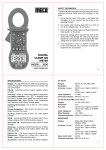
The following example configuration is simple and permits data buffering on the interface
node.
PI Server
Windows OS /
VMS / UNIX
TCP / IP
Windows OS
PI-SDK
PI-OPC
Interface
OPC Server
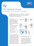
The following configuration places the OPC server on its own computer.
PI Server
Windows OS /
VMS / UNIX
TCP / IP
Windows OS
PI-SDK
PI-OPC
Interface
Windows OS
(or different OS)
OPC Server
For details about related products and technologies, refer to the following OSIsoft manuals:
PI Server manuals
PI API Installation Manual
PI OPCClient User’s Guide
PI Interface Configuration
Utility User Manual
UniInt Interface User’s Guide
DCOM Configuration Guide
2
Chapter 2.
How the OPC Interface Works
At startup, the OPC interface performs the following steps:
1. Connect to PI server (unless disconnected startup is configured)
2. Get tags from PI server
3. Connect to OPC server
4. Create OPC groups
5. Add items to groups
6. Activate groups (unless groups are created as active)
7. Begin data collection
After startup is complete, the OPC interface enters the processing loop, which includes the
following tasks:
Service scheduled input points and process each scan class in turn.
Service output points as events arrive.
Service triggered input points as events arrive.
Check the PI point database for points that are added, edited, and deleted.
If the OPC interface detects new points or changes to existing points, it reloads those points
from the PI Server. The interface processes 25 point updates at a time. If more than 25 points
are added, edited, or deleted at one time, the interface processes the first 25 points, waits 30
seconds or the time specified by UniInt /updateinterval parameter, whichever is lower,
processes the next 25 points, and so on. After all points have been processed, the OPC
interface resumes checking for updates.
During startup, the OPC interface loads all the points that it maintains. After startup, the OPC
interface processes subsequently-updated points periodically, in batches of 25. For efficiency,
if you’ve changed a large number of PI points, stop and restart the interface.
Interface Startup
The OPC interface is started using a Windows batch file that invokes the OPC interface
executable and specifies settings using command line parameters. To ensure a correctlyformatted batch file, do not edit the batch file manually: use PI ICU. For a complete list of
UniInt startup parameters, refer to the UniInt Interface User Manual.
PI Interface for OPC DA
3
How the OPC Interface Works
Reading Data from the OPC Server
Data is read from OPC servers in groups, not as individual items. The OPC interface creates
OPC groups for PI scan classes. (For advise tags in scan class 1, multiple groups might be
created.) The OPC server caches the most recent data. By default, the OPC interface reads
from the cache of an OPC server. When the OPC interface creates a group, it specifies how
often the cache values for the points in that group are to be updated. The requested update
rate is usually the same as the scan rate for the points. The OPC server might decline the
requested rate and return the update rate that it supports for that group. The update rate to
which the OPC server agrees is recorded in the local PI message log file.
Timestamps
The OPC interface can use the timestamps provided by the OPC server or create its own
timestamps at the time that the data is received. Timestamps coming from the OPC server are
in Coordinated Universal Time (UTC), and are sent to the PI system in UTC as well.
If the OPC server provides timestamps, you can use PI ICU to configure the behavior of the
OPC interface as follows:
Option
Description
Interface
Provides
Timestamp
(Default) The OPC interface timestamps each value as it receives. Choose this
option If the OPC server cannot provide timestamps or you do not want to use the
timestamps returned by the OPC server. (/TS=N)
OPC Server
Provides
Timestamp
The OPC interface uses the UTC timestamp provided by the OPC server . (/TS=Y)
Timestamp for
Advise Tags
Only
For polled reads, some OPC servers return the time that the value last changed
rather than the time of the read. This option configures the OPC interface to use the
advise timestamps but provide timestamps for the polled values. For more details
about advise and polled tags, see Polling, Advising and Event Tags. (/TS=A).
For details about reading and writing timestamps from a PI tag when the timestamp is the
value of the tag, see Data Types.
Logging
The OPC interface logs messages about its operation in the local PI message log file. The
following information is logged:
Startup and shutdown status messages
The scan rate configured for each scan class and the actual update rate provided by the
OPC server
The number of points in each scan class, output points, and advise and event tags
Misconfigured points
Points rejected by the OPC server (and other error messages from the OPC server)
OPC server connections attempts and results, including loss of connectivity
4
Buffering
Buffering is temporary storage of the data that the OPC interface collects and forwards to the
PI Server. To ensure that you do not lose any data if the OPC interface cannot communicate
with the PI Server, enable buffering. The PI SDK installation kit installs two buffering
applications: the PI Buffer Subsystem (PIBufss) and the PI API Buffer Server (BufServ).
PIBufss and BufServ are mutually exclusive; that is, on a particular computer, you can run
only one at a time. For details about configuring buffering, refer to the PI Buffering User
Guide.
To ensure data integrity, enable buffering even if the OPC interface runs on the PI server
node, because the OPC server sometimes sends data in bursts, with all values arriving within
the same millisecond. To ensure that the interface and buffering restart when the interface
node is rebooted, configure both as Windows services.
Server Connection Management
Each instance of the OPC interface connects to a single OPC server. To handle multiple OPC
servers, run multiple instances of the OPC interface. Multiple instances of the OPC interface
can be configured to connect to the same OPC server. To enable the OPC interface to collect
data without a connection to the PI server, you can start the OPC interface in disconnected
mode. Refer to the UniInt Interface User Manual for more details.
If the OPC interface cannot connect to the OPC server during startup, it logs the problem and
retries the connection every five seconds until it reconnects. When the OPC server reports
that it is running, the OPC interface connects to it and starts creating groups and adding
items. If the OPC interface loses the connection to the OPC server after the initial connection,
it tries to re-establish the connection. To ensure that no data from the OPC server is lost if the
PI server is inaccessible, configure buffering on the OPC interface node.
Polled, Advise and Event Tags
The OPC interface has three methods of getting data from data sources into tags: polled tags,
advise tags, and event tags, described in detail in the following sections. All three types of
points are received asynchronously by the OPC interface. To assign tag type, set
Location3 as follows:
Tag Type
Location3
Polled
0
Advise
1
Event
2
To assign the scan class for a tag, set Location4. Do not assign the same scan class to both
advise and polled tags; use separate scan classes.
Polled Tags
Polled tags are grouped by scan class, and, if possible, groups are read at the rate configured
for the tag’s scan class. However, the OPC server determines its own update rate for scanning
its data sources, and you can configure the update rate manually (using PI ICU). The OPC
PI Interface for OPC DA
5
How the OPC Interface Works
interface requests the OPC server to use an update rate identical to the scan class, but the
OPC server does not guarantee that the rates match. The PI scan class offset has no effect on
the OPC server, unless the interface is configured for staggered group activation and the OPC
server uses the activation of the group to initiate the scanning cycle.
For details about polled tags, see the Data Access Custom Interface Standard v2.05a from the
OPC Foundation.
Advise Tags
Advise tags are sent to the OPC interface by the OPC server only when a new value is read
into the server’s cache. Scan class 1 is reserved for advise tags, and you can create additional
scan classes for advise tags as required. Be sure that the scan rate is fast enough to capture all
the changes from the data source.
The default maximum number of tags in scan class 1 is 800. Up to 800 tags with the same
deadband can reside in the same group. If there are more than 800 tags with the same
deadband in scan class 1, the OPC interface creates as many groups as needed. (To ensure
best performance, ensure that groups size does not exceed 800 items).To change the default
limit, use PI ICU to set the Number of Tags in advise group field on the OPCInt >Data
Handling page. Your server might perform better with smaller group sizes; a limit of 200
tags per group has proven effective with a number of OPC servers.
Event Tags
Event tags are read by the OPC interface when it receives notification that a trigger tag has a
new event. The PI tag that triggers the read is specified in the event tag’s ExDesc attribute.
When a new event for a trigger tag is sent to the PI snapshot, the PI system notifies the OPC
interface, which reads the values for all the associated event tags from the OPC server. For
v1.0a servers, an asynchronous read is sent to the server’s cache. For v2.0 servers, the OPC
interface performs an asynchronous read from the device.
To configure event tags, specify 0 for scan class. To assign event tags to the same OPC event
group (so they are read together), specify the same integer in the tags’ UserInt2 attribute.
Set the event tag’s ExDesc attribute to the name of the triggering tag. For details about
configuring event tags, refer to the UniInt Interface User Manual.
Frequent device reads can impair the performance of the OPC server. For any asynchronous
read, the OPC server is required to return all of the values together, which can delay the
return of new values to the PI Server if the OPC server encounters a delay in reading the
values. To improve performance in this case, group tags according to the device where the
data originates.
Output Tags and Scan Classes
When a value is written to the OPC server, the OPC interface waits for an acknowledgement
(ACK) from the server. To speed processing of outputs, you can configure multiple output
groups, specifying the number of outstanding writes a group is permitted and the amount of
data to be sent in each write. The OPC server is not required to accept more than one write at
a time from any group, but many servers permit multiple writes to be sent without waiting for
the first one to be ACKed. Even if the server accepts only one write at a time, defining
multiple output groups can improve throughput. If you specify more outstanding writes than
6
the OPC server can accept, the OPC interface reduces its setting to the OPC server’s
maximum.
The interface monitors acknowledgements of writes, and you can specify how long to wait
for the OPC server to acknowledge a write. If no ackowledgement is received in the
specified period, the interface cancels the write and reissues it.
If your OPC server does not acknowledge writes, you can create an alert using the Device
Status health tag. Configure the alert to detect a desired number of queued writes. When the
specified level is reached, the alert sets an alarm state and drops a specified number of values,
oldest or newest.
To assign an output tag to an output group, set its Location4 attribute to the group number.
For load balancing, output tags with Location4 set to 0 are distributed across output
groups (including groups to which output tags are explicitly assigned).
Data Type Compatibility
The data type of a PI tag must be compatible with data type of the corresponding OPC item.
For example, if a string value from the OPC server is to be to put into an Int32 PI tag, the
string must contain a number. If a 64-bit floating-point value is to be put into an Int16 tag,
its value must not overflow the target data type.
The OPC interface specifies the desired data type when requesting information from the OPC
server, and the OPC server is responsible for delivering the requested data type if it can. The
OPC interface normally requests values using the following default data types:
PI PointType
OPC Data Type
Digital
Two-byte Integer (VT_I2)
Int16
Two-byte Integer (VT_I2)
Int32
Four-byte Integer (VT_I4)
Float32
Four-byte Float (VT_R4)
Float64
Eight-byte Float (VT_R8)
String
String (VT_BSTR)
Reading Numeric Tags as Strings
Some OPC servers return certain numeric data types only as strings. To interpret stringformatted Int16, Int32, Float32, and Float64 values, set Location2 to 1. The
OPC interface requests the data as a string (BSTR) and interprets the data as a number.
PI digital tags contain integer values that correspond to specific strings in the digital state
table in the tag's digital set property. Some devices read and write the string value rather than
the integer value. To read and write digital tags as string tags, set Location2 to 1. Make
sure that the strings used by the OPC server are identical to the strings in the digital set,
including punctuation and spaces. For optimal performance, read digital tags as numbers
whenever possible.
PI Interface for OPC DA
7
How the OPC Interface Works
Booleans
Some OPC servers send Boolean values as 0 and -1 when read as integers. This approach
creates a problem when reading that data into a PI digital tag, because "-1" is not the value
that must be stored. To handle the data from such servers, the OPC interface uses the absolute
value of any integer or real values read for digital tags. Because digital tag values are actually
offsets into the digital set for the tag, and a negative offset has no functional meaning, this
issue does not cause problems for properly-written servers.
The OPC interface can also request the item as a Boolean (VT_BOOL). This approach works
only for items that have two possible states, because any non-zero value is interpreted as 1.
To have tags read and written as though they were Booleans, set Location2 to 2.
Four-Byte Integers
If your OPC server does not support the two-byte integer (VT_I2) data type, you can
configure the OPC interface to request the data as a four-byte integer (VT_I4) by setting
Location2 to 3.
Float64 Values
To handle eight-byte floating-point numbers (VT_R8), set the Location2 of the target tag
to 5. PI stores the value as a four-byte floating-point number, with possible loss of precision.
If the number is too large to fit in the tag, a status of BAD INPUT is stored.
Timestamps
The OPC interface does not adjust the timestamps it receives, regardless of the time zone
settings or /TS parameter specified on the command line. Any scaling or transformation is
performed after the string has been translated into seconds, which enables a wide range of
values to be handled.
Converting Timestamps into Seconds
To store a timestamp string (VT_BSTR) as seconds, set Location2 to 6. If the PI tag is an
integer, the OPC interface attempts to translate the timestamp into whole seconds. (Because
Int16 tags can only hold numbers up to 32767, use Int32 tags for time spans longer than
nine hours.) If the PI tag is a floating-point tag, the timestamp is translated into seconds and
stored as a floating-point number.
Reading Timestamps as VT_DATE Data Types
The OPC standard allows the VT_DATE data type, which is an internal representation of a
timestamp. To configure the OPC interface to use the VT_DATE data type for reading the
value from the OPC server or for writing the value to output tags, set Location2 to 7. The
OPC interface translates between VT_DATE and integer, float, or string tags. The OPC
interface does not adjust the timestamps received, regardless of the time zone settings. For
string tags, the format of the string must be specified as above.
8
Timestamp Strings
To configure the format of the timestamp sent by the OPC server using PI ICU, go to the
OPCInt > Data Handling page and specify the format in the Format of Timestamp Strings
field using the following tokens:
Token
Description
cc
Two-digit century
yy
Two-digit year
mn
Two-digit month
mon
Three-character month (Jan Feb Mar, etc.)
dd
Two-digit day
hh
Two-digit hour from 0 to 23
hr
Two-digit hour from 0 to 12
mm
Two-digit minute
ss
Two-digit second
24
Three-digit milliseconds
XM
AM or PM
The position of the tokens and delimiters must specify the format of the timestamp string
precisely. Examples:
Format String
Result
ccyy/mn/dd hh:mm:ss.000
1998/11/29 15:32:19.391
dd mon, ccyy hr:mm:ss XM
29 Nov, 1998 03:32:19 PM
mn-dd-ccyy hh:mm:ss
11-29-1998 15:32:19
hh:mm:ss.000
15:32:19.482
Only one format string can be specified for each instance of the OPC interface. If more than
one format of timestamp needs to be processed, configure additional instances of the OPC
interface with the required format string.
Omitting the Data Type
If your OPC server does not permit clients to specify a data type, set Location2 to 8 for
all your OPC PI tags. Use with caution: The OPC interface might receive data for which no
reasonable conversion is possible. Where possible, always specify the OPC data type that
matches the PI tag.
Transformations and Scaling
You can configure PI points so that the OPC interface performs transformations and scaling.
Transformation and scaling are applied before the value is compared to the exception
parameters for the tag, to ensure that the exception parameters are applied to the value that is
to be sent to PI rather than the raw value.
PI Interface for OPC DA
9
How the OPC Interface Works
Scaling
To configure scaling for a PI OPC tag, set the TotalCode and SquareRoot attributes of
the tag. The Convers attribute specifies the span of the device, and the ExDesc specifies
the device zero (Dzero). Using these values, the OPC interface can translate a value from
the scale of the device to the scale of the tag. Scaling is only supported for numeric tags.
For simple square/square root scaling, set TotalCode and Convers to zero. To configure
how the value is stored, set SquareRoot as follows:
To square a value before sending it to PI. set SquareRoot to 1. For output values, the
square root is calculated before it is written to the device.
To send the square root to PI and the square to the device, set SquareRoot to 2.
Transformation
To transform the value to another scale of measurement or to apply an offset or conversion
factor, or to perform bit masking, configure the settings as shown in the following table. If
SquareRoot is set to 1 or 2, the square root or square of the value is calculated first, then
the formula is applied.
Convers
0
Nonzero
Total
Code
0
1
2
3
Square
Root
10
Input Tags
Output Tags
1
No
effect
(Value)
2
No
effect
(Value)
0.5
0
Defined
[ (Value – Dzero) / Convers ] * Span
+ Zero
1
Defined
[ ((Value) – Dzero) / Convers ] *
Span + Zero
2
Defined
0
(Value)
0.5
(Value)
2
[ (Value – Zero) / Span] * Convers +
Dzero
2
[ ((Value)
+ Dzero
[ ((Value) – Dzero) / Convers ] *
Span + Zero
0.5
[ ((Value) – Zero) / Span] * Convers
+ Dzero
No
effect
Value * Convers
Value / Convers
1
No
effect
(Value) * Convers
2
No
effect
(Value)
0
Defined
(Value / Convers) – Dzero
Defined
2
0.5
* Convers
2
((Value) / Convers) – Dzero
0.5
/ Convers) – Dzero
2
Defined
((Value)
0
Defined
(Value – Dzero)/ Convers
1
5
Operation
2
1
4
Dzero
Defined
2
((Value) – Dzero)/ Convers
0.5
– Dzero)/ Convers
2
Defined
((Value)
0
No
effect
Value + Convers
1
No
effect
(Value) + Convers
2
0.5
– Zero) / Span] * Convers
2
(Value)
0.5
/ Convers
2
(Value) / Convers
(Value + Dzero) * Convers
((Value)
0.5
+ Dzero) * Convers
2
((Value) + Dzero) * Convers
(Value * Convers) + Dzero
((Value)
0.5
* Convers) + Dzero
2
((Value) * Convers) + Dzero
Value – Convers
(Value)
0.5
– Convers
Convers
Total
Code
Square
Root
Dzero
Operation
Input Tags
0.5
+ Convers
Output Tags
2
(Value) – Convers
2
No
effect
(Value)
6
No
effect
No
effect
Value AND Convers
Value AND Convers
7
No
effect
No
effect
Value OR Convers
Value OR Convers
8
No
effect
No
effect
Value = Value XOR Convers
Value = Value XOR Convers
Data Quality Information
The OPC Data Access standard specifies a set of quality flags. The OPC interface translates
the quality flags to the closest approximation in the PI system state table. The low eight bits
of the quality flags are arranged into three fields, quality, sub-status and limit
status, arranged as follows: QQSSSSLL
Handling Data of Questionable Quality
The PI archive stores either the quality or the value in a tag, whereas the OPC server returns
value and quality in separate fields. If a value is good, it is stored in the tag. If a value is bad,
a digital state that describes the quality is stored. For questionable-quality data, you can
configure the OPC interface to treat the values as good and store them, or treat them as bad
and store a digital state. You cannot configure the interface to store a bad-quality value.
To configure handling of questionable-quality data using PI ICU, go to the OPCInt > OPC
Server page and enable the desired option, as shown in the following figure.
Storing Both Values and Quality Information
To record both the values reported and the quality information returned with the values, store
the quality in a separate PI tag. To configure a tag to store the quality for the associated
ItemID , set Location2 to 4. Because OPC qualities are unsigned 16-bit integers, the OPC
interface requires an Int32 tag to store them. The values are stored in PI without any
change, and their status is always GOOD. For details about OPC quality values, download the
OPC Data Access specification from http://www.opcfoundation.org or consult the OPCClient
User’s Guide.
Quality States
Quality data is returned using a bit mask. The first number corresponds to a hexadecimal
value between 0xC0 (11000000) and 0xFF (11111111). The following tables list the values
that are returned.
Good Quality
PI Interface for OPC DA
11
How the OPC Interface Works
Quality
OPC Definition
PI Status
11SSSSLL
Non-specific
Good
Local Override
_SUBStituted
Quality
OPC Definition
PI Status
10SSSSLL
Invalid
Bad Input
Quality
OPC Definition
PI Status
010110LL
Sub-Normal
Bad_Quality
010101LL
Engineering Units Exceeded
Except
110110LL
Not Used by OPC
Questionable Quality
LL=01
Low Limited
Under LCL
LL=10
High Limited
Over UCL
Otherwise
010100LL
12
Inp OutRange
Sensor Not Accurate
LL=01
Low Limited
Under Range
LL=10
High Limited
Over Range
Otherwise
Out of calibration (if not under
or over range)
Invalid Data
010011LL
Invalid
Bad Input
010010LL
Invalid
Bad Input
010001LL
Last Usable Value
No_Sample
010000LL
Non-specific
Doubtful
Bad Quality (PI version 3.3 and higher)
Quality
OPC Definition
PI Status
000111LL
Out of Service
Out of Service
000110LL
Comm Failure
Comm Fail
000101LL
Last Known Value
Scan Timeout
000100LL
Sensor Failure
Equip Fail
000011LL
Device Failure
Unit Down
000010LL
Not Connected
Not Connected
000001LL
Configuration Error
Configure
000000LL
Non-specific
Bad
To replace the default PI digital states with custom states using PI ICU, go to the OPCInt >
Data Handling page and set the Alternate Digital State for Questionable/Bad Qualities
field. To override the default states, you must specify the full set of replacements, and the
numeric values must be contiguous. The following table lists the digital states and PI statuses
that you can override.
Order After
Marker State
Default PI status
Order After
Marker State
Default PI status
1
Bad_Quality
10
Doubtful
2
Under LCL
11
Out of Service
3
Over UCL
12
Comm Fail
4
Inp OutRange
13
Scan Timeout
5
Under Range
14
Equip Fail
6
Over Range
15
Unit Down
7
Invalid Data
16
Not Connected
8
Bad Input
17
Configure
9
No_Sample
18
Bad
Failover
The OPC interface is designed to provide redundancy for both the OPC server (server-lever
failover) and the OPC interface (UniInt or OPC interface-level failover).
Server-Level Failover
The OPC interface can be configured to change to another OPC server when a
problem is detected.
Interface-Level Failover
To ensure against data loss, you can run two instances of the OPC interface on
different machines. If the primary instance fails, the backup instance can take over.
For details about configuring failover, see Configuring Failover on page 35
PI Interface for OPC DA
13
How the OPC Interface Works
Plug-ins (Post-Processing DLLs)
The OPC interface can be configured to use plug-ins, which are DLLs that contain libraries of
routines that perform application-specific data processing before the data is sent to the PI
Server or OPC server. The DLLs and their accompanying files and documentation are
included in the OPC interface installer and are installed into the Plug-ins sub-directory
under the OPC interface directory. Each plug-in package contains user documentation, and
you can download plug-in user guides from the OSIsoft Download Center.
14
Chapter 3.
Installing and Configuring the OPC
Interface
This chapter provides detailed instructions for installing and configuring the OPC interface. A
minimum functional configuration is described, which you can adjust according to your
requirements. For details about features that are common to all UniInt interfaces, refer to the
UniInt Interface User Manual.
To enable you to quickly configure a sample instance of the interface, the OISsoft Knowledge
Base provides a quickstart topic:
http://techsupport.osisoft.com/Support+Solution/11/KB00772.htm
Before installing and configuring, ensure that the following prerequisites are met:
Verify that the PI Server is up and running.
Using OPCClient, verify that the OPC server is up and running and populated
with tags.
Verify that the OPC interface node time zone is set correctly.
On the OPC interface node, install the following:
PI Prerequisites
PI Interface Configuration Tool (ICU)
Installing the OPC Interface
To install the OPC interface, download and run its setup kit. By default, the OPC interface is
installed in the following location:
\Interfaces\OPCInt\
The %PIHOME% directory, which is the root directory under which OSIsoft products are
installed, is defined by the PIHOME entry in the pipc.ini configuration file in the
%windir% directory. To override the default locations, edit the pipc.ini configuration
file.
Recommendation: Reserve the C: drive for the operating system and install the
interface on another drive.
The OPC interface installation directory contains all the files required to configure and run
the OPC interface. The OPCEnum tool, which discovers OPC servers, is installed in the
…\%windir%\system32 directory, except on 64-bit systems, where it is installed in
PI Interface for OPC DA
15
Installing and Configuring the OPC Interface
%windir%\sysWOW64. The OPC libraries, provided by the OPC Foundation and installed
with the OPC interface, are installed in the same directory as OPCEnum.
Configuring the OPC Interface
To configure the OPC interface, you must:
Create any required trusts
Create and configure an interface instance
Configure the Windows service
Configure buffering
Create tags
The following sections describe these tasks in detail.
Note: Even if you are using the same node for both the OPC server and the OPC client,
you must configure DCOM security settings. In this case, make sure that DCOM
permissions have been granted to the accounts under which the OPC server and
the OPC interface run. For details, see the OSIsoft DCOM Configuration Guide.
Creating and Configuring the Interface Instance
For each OPC server intended to exchange data with the PI System, you must create at least
one instance of the OPC interface. For each instance you create, settings are stored in a
separate Windows command file (a .bat file) in the OPC interface installation directory.
Recommendation: If you require multiple instances of the OPC interface, configure
them with unique IDs and point sources, to ensure that you know
where the data written to the PI server originated, and to more easily
trace any problems that arise.
To create an instance of the OPC interface, perform the following steps:
1. Launch PI ICU.
2. Choose Interface > New from BAT file…
3. Browse to the directory where the OPC interface is installed (default is
PIPC\Interfaces\OPCInt), select OPCInt.bat_new and click Open. The
Select PI Host Server dialog is displayed.
4. Specify the PI Server and click OK. ICU displays the settings of the new instance of the
OPC interface.
5. Edit the basic settings as follows.
General tab
Point source: “OPC” or a point source not already in use
Interface ID: 1or a numeric ID not already in use
16
Scan class: Set to desired scan frequency. (Scan class 1 is reserved for advise
tags.) Note that, when defining scan classes, you can spread the server
workload using offsets.
OPCInt tab: On the OPC Server tab, click the List Available Servers button, then
select your server from the drop-down list of servers. If the server resides on another
machine, specify the node name or IP address in the Server Node field before listing
the available servers.
Security Parameters tab: If your OPC server requires clients to use OPC security,
enable OPC security (using PI ICU) and select NT security or Private OPC
security, then enter the user ID and password. Before enabling OPC security, verify
that your OPC server supports it - most do not. Be advised that, when you enable
OPC Private security, user ID and password are stored and transmitted in clear text.
NT security encrypts this data and is therefore the recommended option if your server
requires the use of OPC security.
Creating Trusts
When creating trusts, you have many options. Following is a simple and secure approach,
creating a trust for the following applications:
OPC interface
PI Interface Configuration Utility (ICU)
Buffering
To create each of these trusts using PI System Management Tools, connect to the PI Server
and perform the following steps:
1. Click Security and choose Mappings & Trusts.
2. On the Trusts tab, right-click and choose New Trust… The Add Trust wizard is
launched.
3. Specify a meaningful name and description.
4. Configure settings as follows:
Trust
Type
Application Name
Network path
PI User
OPC
interface
PI-API
application
OPCpE
Name of the
interface node or
IP address plus
netmask
255.255.255.255
OPC tag data owner
PI ICU
PI-API
application
PI-ICU.exe
Name of the
interface node or
IP address plus
netmask
255.255.255.255
Dedicated PI identity with the
precise permissions required
(database read access, read
ptsecurity and read-write
permission for OPC points)
Buffering
PI-API
application
BufServ: “APIBE”
PIBufss: Pibufss.exe
Name of the
interface node or
IP address, plus
netmask
255.255.255.255
OPC tags’ data owner
PI Interface for OPC DA
17
Installing and Configuring the OPC Interface
Verifying Successful Startup
To display the message log, launch PI SMT and choose the Operation > Message Logs
option. Using PI ICU, start the interface in Windows Explorer by double-clicking the .bat
file. Watch log for messages indicating success or errors.
Configuring the Windows Service
To ensure that the OPC interface instance starts whenever the interface node is rebooted,
configure the instance as a Windows service, as follows:
1. In PI ICU, click Service.
2. To ensure that buffering is running when the interface starts, click bufsrv (pre 3.4 PI
Servers) or pibufss (3.4 and higher) in the Installed services list, then click the leftarrow button to add it to the Dependencies list. (If prompted, update service
dependencies.)
3. Set Startup Type to Auto.
4. Click the Create button.
5. To start the service, click
.
To verify that the service is created and is running, use the Windows Services control panel.
Enabling Buffering
To start buffering:
1. In ICU, choose Tools > Buffering. The Buffering dialog is displayed.
2. Click Enable buffering with PI Buffer Subsystem.
3. To start the buffering service, click PI Buffer Subsystem Service, then click
.
To verify that buffering starts successfully, check the message log for messages indicating
that the buffering application connected to the PI Server. To verify that the configuration is
working as intended, reboot the interface node and confirm that the OPC interface service and
the buffering application restart.
18
Creating Tags
To build individual tags manually, use PI System Manager (choose Points > Point Builder).
Basic tag settings are as follows:
Field
Description
PointSource
Identifies all tags that belong to this instance of the OPC interface. Specify “OPC”
or the point source that you defined when configuring the interface instance.
Location1
Specifies the OPC interface instance ID, which is displayed on the PI ICU General
tab.
Location2
To use a data type other than the default for the PI tag data type, set Location2 to
the appropriate value. For details, see Data Type Compatibility
Location3
Tag type (0=polled, 1=advise, 2=output).
Location4
Specifies the scan class. For tags that are read when a specified trigger tag gets a
value (event tags), set to 0 or the required number. For details, see Event Tags.
Location5
Optional deadband value for advise tags.
ExDesc
Specifies event trigger tags, Long ItemID, Dzero for scaled tags, and/or ItemID to
get the timestamp for an output value.
InstrumentTag
OPC ItemID that corresponds to the PI tag you are defining. Case-sensitive. To
display OPC server tags, use PI OPCClient.
UserInt1
Maps a tag value to an element in an OPC array item. For tags that are not
mapped to an OPC array, set UserInt1 to 0 (zero).
To populate the PI Server with the tags that are defined in your OPC server, use PI
OPCClient or OPCtoCSV (installed in PIPC\PI OPC Tools\PI_OPCtoCSV) to export
OPC items to an Excel file (.csv), then use PI System Management Tool’s Tag
Configurator feature to load the tags into the PI Server
Note: To permit PI Tag Configurator to create tags, you must define a trust or configure
permissions that enable Microsoft Excel to write to the PI Server.
To export OPC tags and create the corresponding PI tags, perform the following steps:
1. Launch PI OPCClient and connect to your OPC server.
2. To select the OPC tags you want to export, create a group (click
tags to it.
) and add the desired
3. Choose File > Save As… and specify the name and location of the export file.
4. Click Save. PI OPCClient creates a .csv file containing the OPC tags you selected.
5. In PI SMT, launch Microsoft Excel by choosing Tools > Tag Configurator…
6. In Microsoft Excel, open the .csv file containing the exported OPC tags.
7. Examine the generated entries to ensure that the desired points are listed. If any entries
have “Unknown” in the pointtype column, specify the desired data type for the point.
8. To generate the PI Points, choose PI SMT > Export Tags… The Export PI Tags dialog
is displayed.
9. Choose the target PI Server and click OK. Examine the list of results to verify that the
tags are created.
PI Interface for OPC DA
19
Installing and Configuring the OPC Interface
Optional Tasks
Following tasks are useful but not required.
Configure diagnostics: Diagnostic tags enable you to track the activity and
performance of the OPC interface. Note that the OPC interface does not support
scan class performance points. For details about diagnostic and health points,
refer to the UniInt Interface User Manual.
Configure disconnected startup: Disconnected startup enables the OPC
interface to start even if the PI server is not available. For details, refer to the
UniInt Interface User Manual.
Configure failover: Failover enables the PI System to switch to another instance
of the OPC interface if the currently-running instance fails. For details, see
Configuring Failover.
Install the PI Interface Status Utility: This utility enables you to monitor the
state of the OPC interface. For details, see the PI Interface Status Utility (ISU)
User Manual.
If you intend to use digital tags, define the appropriate digital state sets.
20
Chapter 4.
Configuring the Windows Service
To ensure that the OPC interface restarts when the OPC interface node is rebooted, configure
it as a Windows service.
To install the OPC interface as a service using PI ICU, perform the following steps:
1. Launch PI ICU and click on the Service tab in the PI ICU window.
2. Set the fields as described in the following table.
Field
Description
Service name
Descriptive name of the OPC interface service.
ID
Numeric ID of the OPC interface instance. Must be unique for each instance.
Display name
The service name displayed in the Windows Services control panel. The default
display name is the service name with a “PI-” prefix. You can override the default.
To ensure that OSI-related services are sorted together in the Services control
panel, retain the “PI” prefix.
Log on as
The Windows account associated with the service. The user must have DCOM
permissions configured on the OPC. Set password expiration to “Never.”
Password
Password, if any, for the preceding user.
Dependencies
Any services that the OPC interface depends on. The only dependency is the
TCP/IP service, which is preconfigured. If buffering is enabled, you are prompted
to create a dependency on the buffering service.
Startup Type
Specifies whether the OPC interface service starts automatically when the OPC
interface node is rebooted. Generally, OPC interface services are set to start
automatically.
3. To create the service, click Create.
4. To start the service click
.
You manage the service as follows:
To verify that the service is running, use the Windows Services control panel applet.
To stop the service, click
.
To start the service interactively (usually done only for debugging), use Windows
Explorer to browse to the batch file for the OPC interface instance, then double-click it.
To remove the service, stop it and click Remove.
If the OPC interface can connect to the PI server when run interactively (from the command
line or Windows Explorer) but not when run as a service, check the DCOM permissions and
consult the local PI message log file and Windows Event Viewer.
PI Interface for OPC DA
21
Chapter 5.
Configuring PI Tags
The PI tag (also called a “point”) is a time-stamped record of a single set of measurements
(for example, tank temperature). If you misconfigure tags, the OPC interface cannot correctly
transmit the data from the OPC server to the PI Server. The following sections tell you how
to configure tags correctly.
Note: To populate the PI Server with the tags that are defined in your OPC server, use
PI OPCClient or OPCtoCSV to export OPC items to an Excel file (.csv), then use
PI System Management Tool’s Tag Configurator feature to load the tags into the
PI Server. For details, see Creating Tags.
Tag Attributes
To define PI OPC tags, you configure, at a minimum, the following attributes
Tag name
Point source
Data type
Interface instance
Tag type
Scan class
Instrument tag
Depending on the type of tag you are creating, a few other setting might be required. The
following sections describe basic tag settings in more detail.
Tag Name
When assigning names to PI tags, follow these rules:
The tag name must be unique.
The first character must be alphanumeric, underscore (_), or percent sign (%).
Control characters such as linefeeds or tabs are illegal, as are the following characters:
*’?;{}[]|\`‘“
PI Interface for OPC DA
23
Configuring PI Tags
The following table indicates the maximum length of the length attribute, which depends on
the combination of PI API and PI server that you have installed.
PI API
PI Server
Maximum Length
1.6.0.2 or higher
3.4.370.x or higher
1023
1.6.0.2 or higher
Below 3.4.370.x
255
Below 1.6.0.2
3.4.370.x or higher
255
Below 1.6.0.2
Below 3.4.370.x
255
If your PI Server is earlier than version 3.4.370.x or the PI API version is earlier than 1.6.0.2
and you want to create tags with names that exceed 255 characters, you must enable the PI
SDK. See Appendix B PI SDK Options for details.
Point Source
The point source is an identifier that associates a tag with an OPC interface instance, enabling
the OPC interface to query the PI Server for the tags that it updates. This field is not casesensitive. In the OPC interface batch startup file, point source is specified using the /PS
command-line parameter.
Recommendation: To ensure that you can track the interface instance responsible for
an archive entry, use a different point source for each instance of
the OPC interface. This approach also speeds up interface startup.
The following point sources are reserved:
Point Source
Description
T
Totalizer Subsystem
G and @
Alarm subsystem
R
Random interface
9
RampSoak interface
C
Performance equations subsystem
Point Type (Data Type)
Point type specifies the data type of the point. Typically, OPC item data types do not need to
match PI tag data types exactly, but the data types must be compatible. For example, integer
values from a device can be sent to floating-point or digital PI tags. Similarly, a floating-point
value from the device can be sent to integer or digital PI tags, although the values might be
truncated.
The OPC interface supports all PI tag types except BLOB. However, some OPC servers lack
support for the full range of PI tag types. To determine what tag types are supported by your
OPC server, refer to the vendor-supplied documentation.
If the tag type defined in PI does not match the canonical data type defined in the OPC server,
the OPC interface attempts to translate the data. To determine whether the tag can be read as
the type needed, use the PI OPCClient to try to read the tag directly from the OPC server. For
more information on data type compatibility, see Data Type Compatibility.
24
Interface Instance (Location1)
Location1 specifies the instance of the OPC interface to which the tag belongs. The value
of this attribute must match the ID configured for the OPC interface instance. This setting
plus point source identify the interface instance that writes to a particular point. (/ID)
Data Type Handling (Location2)
Location2 configures handling of data types. Valid settings are as follows:
Value
Description
0
Normal processing; no special handling is used.
1
Read and write value as string. For digital tags, the strings read from the OPC server must
match the strings in the digital state set used by the tag. For integer and real tags, the OPC
interface requests a string value, and translates it to a number. .
2
Read value as a Boolean. Booleans having only two possible values, zero and nonzero. For
numeric tags, any value but 0 (False) is set to -1 (True). Use this option to correctly convert
an OPC server Boolean into the PI Digital State, to prevent the PI tag from receiving “Bad
quality” values for a Boolean when it is True.
3
Read value as a four-byte integer. This setting is provided to accommodate servers which
cannot send the value as a two-byte integer, which is how Digital tags are normally read.
4
Stores the quality of the item rather than the value.
5
Request real tags as VT_R8 items (eight--byte real). By default, the OPC interface requests
real tags as VT_R4 items (four-byte real). For float32 tags (including all PI2 Real tags),
values that cannot fit in a 32-bit floating-point number lose precision. This setting is included
to support servers that do not translate VT_R8 data to VT_R4 data and to permit the use of
Float32 tags where the benefit of greater precision is not worth the overhead of using
Float64 tags.
6
Read timestamps from the OPC server as strings and transform them into seconds. The PI
tag can be an int or a float. The format of the timestamp string is specified in the startup file
with the /TF parameter.
7
Read timestamps from the OPC server as VT_DATE variables. These values can be
translated into timestamp strings or passed to PI as a number of seconds, suitable for use in
computations. If the value is translated into a string, the timestamp format is used (/TF).
8
Directs the OPC server to send the canonical data type. The OPC interface tries to
transform the value into the proper data type for the PI tag. Use with caution, because the
transformation can fail if the source data type is not compatible with the PI tag data type, or
if the value cannot be represented using the PI tag data type.
>= 1024
When a post-processing DLL is used with the OPC interface, directs the data to be
processed by the DLL. Adding any of the above settings (1-8) to 1024 enables the
abovementioned functionalities to be used as well. For more information, see the TimeArray
plug-in user manual.
PI Interface for OPC DA
25
Configuring PI Tags
Tag Type (Location3)
Location3 specifies whether this tag is a polled, advise, event, or output tag.
Loc3
Description
0
Polled or event
1
Advise
2
Output
3
Polled watchdog used with server-level failover
4
Advise watchdog used with server-level failover
For an advise tag, the OPC interface registers for updates with the OPC server, and the OPC
server sends new values to the OPC interface (at a rate not exceeding the update rate for the
group.)
Scan Class (Location4)
Location4 configures the scan class for the PI tag. The scan class determines the
frequency at which input tags are scanned for new values. Location4 must be a positive
number. For trigger-based tags, set Location4 to zero. For output tags, Location4
configures the output class. When necessary for load balancing, the interface distributes tags
in scan class 1 across multiple OPC groups. Scan classes other than scan class 1 are assigned
to separate groups for load balancing.
You can configure scan classes for the OPC interface as follows:
Tag
Maximum Number of
Groups
Polled
200
Advise
600
Event
199
Output
No maximum
Specify scan frequency and optional offset using the following format:
HH:MM:SS.##,HH:MM:SS.##
Examples:
/f=00:01:00,00:00:05 /f=00:00:07
or, equivalently:
/f=60,5 /f=7
If you omit HH and MM, the scan period is assumed to be in seconds. Subsecond scans are
specified as hundredths of a second (.01 to .99).
To define a time of day at which a single scan is performed, append an “L” following the
time: HH:MM:SS.##L
The OPC standard does not guarantee that it can scan data at the rate that you specify for a
scan class. If the OPC server does not support the requested scan frequency, the frequency
assigned to the class is logged in the pipc.log file. If the interface workload is heavy,
26
scans can occur late or be skipped. For more information on skipped scans, see the UniInt
Interface User Manual.
Scanning Offsets
To mitigate the interface and OPC server workload, you can use the offset to stagger
scanning. If an offset is specified, scan time is calculated from midnight on the day that the
interface was started, applying any offset specified. In the above example, if the interface was
started at 05:06:06, the first scan occurs at 05:07:05, the second scan at 05:08:05, and so on.
If offset is omitted, scanning is performed at the specified interval, regardless of clock time.
Offsets determine when the interface asks the OPC server for the current values for polled
classes. They do not control the behavior of the OPC server, and have no effect on advise
classes unless the /GA parameter is specified to stagger the activation of groups. In this case,
the offsets are used to time the activation of all groups except for scan class 1 (which is
reserved for advise tags).
Update Rates
The OPC server reads data from the device according to the update rate for the group in
which the item resides. By default, the update rate is the same as the scan rate. To override
the default using PI ICU, browse to the OPCInt > OPC Server > Advanced Options page
and enter the desired update rates in the Update Rates section. (/UR)
For polled groups, configuring an update rate that is shorter than the scan period can ensure
that the interface is receiving current data. For example, if the scan period is five seconds but
the update rate is two seconds, the data is no more than two seconds old when it is read.
However, note that a faster update rate increases the OPC server workload.
For advise groups, assign identical update and scan rates, with one exception: if you are using
UniInt Failover Phase 1, then to ensure that the interface sees new values for failover
heartbeat tags as soon as possible, set the update rate to half the scan period. This
configuration reduces the risk of thrashing, where control switches back and forth needlessly.
Dedicate a scan class with faster update rate to the failover heartbeat tags. OSIsoft
recommends using Phase 2 failover instead.
OPC Deadband (Location5)
Note: Under the OPC standard, deadband processing is optional for servers. Before
attempting to configure advise tags, be sure that your OPC server supports
deadband processing. If the OPC server does not support deadband processing,
the PI tag is updated for all value changes to the tag, depending on the exception
parameters specified for the PI tag.
For advise tags, Location5 specifies a deadband value for analog OPC items. The
deadband is used to reduce the amount of network traffic from the OPC server to the OPC
interface. If the change between the last value read and the new value is less than the
deadband, the OPC server does not send the value to the OPC interface. Note that OPC
deadband processing is not the same as PI deadband (exception) processing.
The EuMin and EuMax attributes in the OPC item definition specify the value range for the
tag. These attributes correspond to the Zero and Span attributes in the PI tag definition. To
configure the deadband, specify a percentage of the range multiplied by 100. For example, if
PI Interface for OPC DA
27
Configuring PI Tags
the OPC server tag is defined as analog with an EuMin of -10 and an EuMax of 10, and
Location5 contains 2500 (meaning 25%), data is sent to the OPC interface only when the
difference between the new value and the old value is at least 5 (25% of 20 = 5). PI
exception processing continues to be applied to the values received by the interface. The
deadband only affects the values sent by the OPC server.
OPC ItemID (InstrumentTag)
The InstrumentTag attribute maps the tag to an OPC item. This field must exactly match
the item name as defined on the OPC server, including any punctuation, spaces, and case. To
verify an ItemID, use PI OPCClient. If the OPC server supports browsing, choose List
Server’s Tags to see a list of defined ItemIDs. To display the full ItemID required for
InstrumentTag field, double-click the ItemID in the list
The maximum length of the InstrumentTag attribute depends on the versions of the PI
Server and API in use. If PI API is version 1.6.0.2 or higher and PI Server is 3.4.370.x or
higher, the maximum length is 1023. For all lower versions, the maximum is 32. If you are
running lower versions and require more than 32 characters to specify the instrument tag, you
must enable the PI SDK or use the extended descriptor to specify the OPC ItemID.
Extended Descriptor (ExDesc)
The extended descriptor attribute is a multi-purpose field that is used as follows:
Event-based data collection: To define an event tag, set this attribute to
event=tagname. When the specified tag has an exception event, the tags for which it
is the trigger are read from the OPC server.
Dzero for scaled tags: When the device returns values that must be scaled to fit the range
of values stored by the tag, store the device zero in ExDesc. To specify the device span,
use the Convers attribute. The format for specifying the device zero is
Dzero=nnnnn.nnn
Note: If the ItemID for this point is longer than 32 characters and the PI SDK is disabled,
the ItemID must specify the ExDesc as instr=ItemID. The ItemID must exactly
match the ItemID defined on the OPC server. If the ItemID contains a comma or
space, enclose it in double quotes.
OPC ItemIDs might have trailing spaces, which can be truncated if not using the PI SDK
and specifying the ItemID in the InstrumentTag field. To include the trailing blanks,
enclose the ItemID in double quotes.
Target OPC item for output tag timestamp: To direct the timestamp of an output tag to
an OPC item, specify the target ItemID in ExDesc. The format written depends on the
data type of the ItemID that is to receive the timestamp, as follows:
Tim=ItemID
Dat=ItemID
Tim: The timestamp is written as a string (VT_BSTR), formatted as configured for
the OPC interface instance (/TF)
Dat: The timestamp is written as a VT_DATE.
28
VT_DATE is a universal (UTC) format that does not depend on the time zone or
daylight savings time setting. For VT_BSTR, the timestamp comes from the PI
Server and is not adjusted for differences in time zone or daylight savings time
setting. In error messages related to this timestamp ItemID, the OPC interface reports
a generated tagname of the form TS:xxxxxx, where xxxxxx is the name of the PI
output tag.
If you use this attribute to specify more than one setting, put a comma between the
definitions. By default, leading and trailing spaces are stripped from entries in this attribute.
To preserve leading and trailing spaces, enclose your entry in double quotes.
SourceTag
For output points (points that write data to the OPC server), this attribute specifies the PI tag
from which data is read. See Output Points for more information.
TotalCode
This attribute contains a code that specifies how the value is to be scaled. TotalCode is
used in conjunction with the SquareRoot, Convers, and ExDesc attributes. See
Transformations and Scaling for details.
SquareRoot
Specifies that the square or square root of the value is to be used. See Transformations and
Scaling for details.
Convers
For scaled tags, this attribute contains the device span. The device item can have a zero and a
span, which define the actual span of values that the device sends. The OPC interface can use
these two values to translate the units used by the device to the units defined for the PI tag.
The Convers attribute can also contain an offset or multiplier. See Transformations and
Scaling for details.
OPC Array Index (UserInt1)
UserInt1 maps a tag value to an element in an OPC array item. For tags that are not
mapped to an OPC array, set UserInt1 to 0 (zero). Ensure that all PI tags that are mapped
to the same OPC array have identical settings for InstrumentTag, ExDesc, and all
location attributes.
An OPC array contains multiple values plus a single timestamp and a quality field. These
items can be identified by using the PI OPCClient tool to read the item and examining the
data type returned by the OPC server. If it is an array item, the type of the value is
VT_ARRAY | VT_other, where VT_other is a data type such as VT_R4 or VT_I2. The
values in the array are sent as one data item and they all have the same data type.
PI does not support tags with an array type, so values must be assigned to a number of
individual tags. The first value in the array maps to the PI tag that has UserInt1 set to 1,
PI Interface for OPC DA
29
Configuring PI Tags
the second to the tag with UserInt1 set to 2, and so on. If these values need to be
processed as different data types, use the Location2 attribute for the PI tag with
UserInt1=1 and the settings for scaling and transformation for each individual tag to
configure how the OPC interface handles the individual value. The OPC interface receives
the data using the data type specified by the Location2 value for the tag with UserInt1=1, then
processes the value according to how the individual tag is configured. Note that some servers
cannot provide array data using any data type other than the canonical data type (the one
displayed in the PI OPCClient if you omit data type). For those servers, you must either use a
PI tag with the correct data type, or set Location2 to 8 to configure the interface to ask for the
canonical data type. For maximum efficiency, always use the canonical data type.
Event Group (UserInt2)
This attribute assigns an event group to an event tag. For tags that are not event tags, set
UserInt2 to 0 (zero). See Event Tags for details.
Scan
This attribute enables or disables data collection for the tag. By default, data collection is
enabled (Scan is set to 1). To disable data collection, set Scan to 0. If the Scan attribute is
0 when the OPC interface starts, the OPC interface does not load or update the tag. If you
enable scanning while the OPC interface is running, the time required for data collection to
start depends on how many tags you enable, because they are processed in batches. For
efficiency, if you need to enable scanning for a large number of tags, stop and restart the
interface. If a tag that is loaded by the OPC interface is subsequently edited so that the tag is
no longer valid, the tag is removed from the OPC interface and SCAN OFF is written to the
tag.
Shutdown
By default, the PI shutdown subsystem writes the SHUTDOWN digital state to all PI points
when PI is started. The timestamp that is used for the SHUTDOWN events is retrieved from a
file that is updated by the snapshot subsystem. The timestamp is usually updated every 15
minutes, which means that the timestamp for the SHUTDOWN events is accurate to within 15
minutes in the event of a power failure. For additional information on shutdown events, refer
to PI Server manuals.
Note: The SHUTDOWN events that are written by the PI shutdown subsystem are
independent of the SHUTDOWN events that are written by the OPC interface.
To prevent SHUTDOWN events from being written when PI Server is restarted, set the
Shutdown attribute to 0. To configure the PI shutdown subsystem to write SHUTDOWN
events only for PI points that have their Shutdown attribute set to 1, edit the
\\PI\dat\Shutdown.dat file, as described in PI buffering documentation.
When the PI Server is shut down, the buffering program continues to collect data, making it
undesirable to write SHUTDOWN events to the PI points for the OPC interface. Disabling
shutdown is recommended when sending data to a Highly Available PI Server Collective.
30
Exception Processing
The ExcMax, ExcMin, and ExcDev parameters control exception reporting in the
OPC interface. To turn off exception reporting, set ExcMax, ExcMin, and ExcDev to
0. See the UniInt Interface User Manual for more information about exception processing.
ExcMax
This attribute configures the maximum time period allowed between sending values to the PI
Server. This setting applies to both advise and polled tags. For advise tags, if the OPC
interface does not receive a value after the specified number of seconds and does not detect a
dropped connection, it sends the last value received to the PI server with the timestamp set to
the current time. For polled tags, the OPC interface sends a value to the PI server if it has not
sent one in the last ExcMax seconds, even if the new value does not pass ExcDev tests.
ExcMin
This attribute configures the minimum time period between values sent to the PI Server.
ExcDev
This attribute configures the minimum change from the last value sent to the PI Server
required for the OPC interface to send a new value.
Output Points
Output points send data from the PI server to the OPC server. Note that only good values can
be sent. System digital states are not sent to OPC items. To configure an output point, edit the
point using PI Point Builder and specify the following settings:
Set Location1 to the OPC interface ID of the OPC interface instance
Set Location3 to 2.
Specify the ItemID (the OPC item to be written).
(Optional) Specify the source point (the PI point that contains the value to be written to
the OPC server). Not required if you intend to send the value directly to the output item
without copying the values and timestamps to a PI tag.
(Optional) Set Location4 to the desired output group. Output tags with Location4
set to 0 are distributed across output groups for load balancing.
There are two mechanisms for triggering an output: configuring a separate source point, and
writing new values to a snapshot, as described in the following sections.
Use a Source Point
To configure the output point using a source point, set the SourceTag attribute to the name of
another PI tag that will contain the values that you want written to the OPC item. When the
source point is successfully updated, the new value is written to the target OPC item. If the
OPC interface succeeds in updating the OPC item, it writes the value and timestamp to the
output point. If the OPC interface does not succeed in updating the OPC item, it writes a
PI Interface for OPC DA
31
Configuring PI Tags
digital state that is descriptive of the error to the output point. For output tags, a "success"
status indicates that the OPC server item has been updated, but there's no guarantee that the
corresponding data source has been updated. To verify that the data source is updated, create
a corresponding input tag and add logic to ensure that the values of the input and output tags
match.
The point source of the output point must match the point source of the interface instance, but
the source point can be associated with any point source. The data type of the source tag must
be compatible with that of the output point.
No Source Point
To use the same PI tag as the source and the output point, leave the SourceTag attribute
blank. Any means of updating the snapshot value of the output tag is acceptable. To trigger
the output to the target OPC item, the timestamp must be more recent than the previous
timestamp, regardless of whether the value changes. The value that you enter into the output
point’s snapshot is written to the target item on the OPC server. Any new value is sent to the
OPC item.
Event Tags
Event tags are configured with a trigger tag. When the trigger tag receives a value, the event
tag is read. To create event tags, set Location4 to 0 and specify the name of the trigger
tag in the ExDesc attribute using the following format:
TRIG=’triggertagname’ event_condition
Enclose the trigger tag name in single quotes. To treat all changes as triggering events, omit
event_condition. For more information about the event_condition argument, see
the UniInt Interface Users Manual.
By default, the server is requested to update its cache every second for every event tag
defined. OPC v2.0 servers always read event tags from the device, not the cache. To
minimize the overhead incurred when the OPC server updates the cache, set the event rate
(/ER) to a high value such as eight hours. For v1.0a OPC servers, asynchronous reads come
from the cache. The cache does not need to be updated frequently for all event tags, so you
can increase the event rate.
To define a set of event tags that are read together in the same OPC event group, assign
identical integer values to the PI tags’ UserInt2 attribute. (For example, a plug-in DLL
that post-processes data might require the data to be sent in a single group.)
For efficiency with v1.0a servers, separate event tags into groups based on the triggering
event. For v2.0 servers, separate event tags according to the data source. The OPC v2.0
standard requires that all asynchronous reads originate from the device rather than from the
server’s cache, so set the cache update rate high and do not group values that come from
different devices. The following example tag definitions illustrate this approach:
Tag
32
ExDesc
InstrumentTag Loc1 Loc2 Loc3 Loc4 Loc5 UserInt1 UserInt2
PM1_Temp.PV TRIG=PM1_Trigger
ItemID1
1
0
0
0
0
0
1
PM1_Rate.PV
TRIG=PM1_Trigger
ItemID2
1
0
0
0
0
0
1
PM2_Temp.PV TRIG=PM2_Trigger
ItemID3
1
0
0
0
0
0
2
In the preceding example, PM1_Trigger and PM2_Trigger are tags that are updated either by
this OPC interface instance, another interface, or by manual entry. When PM1_Trigger gets a
new event in the PI snapshot, the OPC interface sends the OPC server a “read” command that
requests data for both PM1_Temp.PV and PM1_Rate.PV. Both values are returned in a single
call. Likewise, when PM2_Trigger gets an event in the snapshot, the OPC interface requests a
value for PM2_Temp.PV.
Reading OPC Array Item Tags
OPC servers can contain arrays of data, which are composed of multiple values of the same
data type plus a single quality and timestamp. Because the PI server does not support array
data types, you must configure one tag for each array element that you want to store in the PI
system. (or use the TimeArray plug-in; for details, see the TimeArray plug-in user guide).
To define a PI tag to contain an element from an OPC array, specify the ItemID of the array
item in the InstrumentTag attribute and set Userint1 to the index number of the
element in the array. You must define a tag for the first array element (Userint1 = 1), even
if you do not require its data. However, you do not need to define tags for all array elements,
just the first one and any individual elements of interest.
All PI tags configured for an OPC array must have identical settings for PointSource,
Location1, and Location4 (and UserInt2, if they are event tags). For advise tags, set
Location3 to 1. For polled tags, set Location3 to 0.
When configuring tags to read OPC arrays, note the following:
You must define a tag that reads the first array element.
Assign the tags to the same scan class.
To optimize CPU usage, do not use the same scan class to read more than one OPC array.
If you need to read the same OPC array element into more than one tag,you must assign
the tags to different scan classes.
Reading OPC Arrays as Event Tags
Multiple scan classes can have the same scan period, and event classes are a logical grouping
of tags. For efficiency, put event arrays into their own scan classes with any other tags that
need to be read with the array.
If an array tag from the OPC server is read into multiple PI tags, each PI tag receives the
value of the array element indexed by the UserInt1 setting and the same timestamp and
quality, because an array contains multiple values but only one timestamp and quality. To
read an array tag into a single PI tag, you must use the TimeArray plug-in, which stores an
array of values into a single PI tag as successive data values, incrementing the timestamp that
came with the array by a configured interval for each value. For details, refer to the
TimeArray plug-in manual.
Configuring arrays that are read as event tags is complex: because only the first array item
(with UserInt1=1) causes a read, you must create a dummy trigger tag to use with the rest
of the array items. That tag must have a point source that is either unused or used for manual
entry tags (lab data usually is entered manually, so “L” is often used as the point source for
PI Interface for OPC DA
33
Configuring PI Tags
manual entry tags). In the following example, the trigger tag is called TriggerTag and the
dummy trigger tag is called DummyTrigger.
Tag
ExDesc
InstrumentTag loc1 loc2 loc3 loc4 loc5 UserInt1 UserInt2
Array0001.PV TRIG=TriggerTag
Data.Array
1
0
0
0
0
1
1
Array0002.PV TRIG=DummyTrigger
Data.Array
1
0
0
0
0
2
1
Array0003.PV TRIG=DummyTrigger
Data.Array
1
0
0
0
0
3
1
Because all the tags in an array must belong to the same group, even if the OPC server is v2.0
and some part of the array data comes from a different device than the rest of the array data,
all the array tags must be configured to be in the same event group.
Reading OPC Quality Into a Digital Tag
To store OPC quality in a digital tag, use transformations and scaling to translate quality to a
digital state set of Bad Value, Questionable Value, Invalid Value, or Good
Value. To define such a tag, set Location2 to 4 to read the quality of the item rather
than its value, then define a mathematical transformation that translates the quality values to
an integer from 0 to 3. Divide the quality number by a conversion factor that produces the
proper number.
OPC quality is returned in ranges of values, as follows:
Range
Description
Less than 0x40
Bad Value
Greater than or equal to 0x40 and less than 0x80
Questionable Value
Greater than or equal to 0x80 and less than 0xc0
Not used by OPC
Greater than or equal to 0xc0
Good Value
Because each range has the same size (decimal 64), you can use a simple conversion to obtain
the corresponding digital state, as follows:
Convers
TotalCode
SquareRoot
Dzero
Operation
Not 0
3
0
Defined
Input tags:
Value = (Value / Convers) – Dzero
Output tags:
Value = (Value + Dzero) * Convers
Define the point attributes as follows:
34
Convers
64
TotalCode
3
SquareRoot
0
ExcDesc
“Dzero=0”
Chapter 6.
Configuring Failover
The OPC interface provides two methods for configuring failover. UniInt failover ensures
that, if one instance of the OPC interface fails, another instance can take over data collection.
Server-level failover ensures that, if the OPC interface stops receiving data from the currently
connected OPC server, it can switch to another OPC server and resume data collection.
Note: You can configure both OPC server-level and UniInt interface failover. If you are
configuring both, configure and verify UniInt failover first. Disable UniInt failover
and configure and test server-level failover separately, then re-enable UniInt
failover.
UniInt Failover
UniInt failover ensures against data loss by enabling a backup OPC interface instance to take
over data collection if a primary instance fails. There are two approaches to configuring
failover: synchronization through the OPC server (phase 1 failover), and synchronization
through a shared file (phase 2 failover). This guide tells you how to configure phase 2
failover.
Note: Phase 1 failover is now deprecated and is not recommended. For details, contact
OSIsoft Technical Support. For more details about UniInt failover, refer to the
UniInt Interface User Manual.
Failover works as follows: you configure two identical instances of the OPC interface on two
different computers. One instance functions as the primary instance and the other one as the
backup, depending on which one is started first. If the primary fails, the backup becomes the
primary and takes over transmitting data from the OPC server to the PI server. If that
interface subsequently fails and the other interface has been restored, the other interface
becomes primary and resumes transmitting data. (Note that “primary” and “backup” are terms
used to clarify operation. Failover seeks to keep a running instance of the OPC interface
connected with a functional OPC server, so, in action, either interface might be primary.)
If the OPC interface instances are configured to use disconnected startup, the interfaces can
start and failover even if the PI Server is unavailable, as long as they both have access to the
shared file.
How UniInt Failover Works
Shared-file (Phase 2) UniInt failover uses PI tags to control failover operation. Status
information from the tags is maintained in a shared file, removing the requirement for a PI
PI Interface for OPC DA
35
Configuring Failover
server connection after the instances are running. If the shared file cannot be accessed, the
OPC interface instances use the PI server to exchange control data.
The following diagram shows a typical setup operating normally. The solid magenta lines
show the data path from the OPC interface nodes to the shared file.
Data register 0
.
.
.
Data register n
DataSource
DCS/PLC/Data Server
Process Network
IF-Node1
PI-Interface.exe
/host=PrimaryPI
/UFO_ID=1
/UFO_OTHERID=2
/UFO_TYPE=HOT
/UFO_SYNC=\\FileSvr\UFO\Intf_PS_1.dat
FileSvr
.\UFO\Intf_PS_1.dat
IF-Node2
PI-Interface.exe
/host=SecondaryPI
/UFO_ID=2
/UFO_OTHERID=1
/UFO_TYPE=HOT
/UFO_SYNC=\\FileSvr\UFO\Intf_PS_1.dat
Business Network
Client
Process Book
DataLink
PrimaryPI
PI Server
Role = 1
SecondaryPI
PI Server
Role = 2
During normal operation, the primary OPC interface collects data from the OPC server and
sends it to the PI server. The ActiveID point and its corresponding entry in the shared file are
set to the failover ID of the primary instance. Both primary and backup instances regularly
update their heartbeat value, monitor the heartbeat value and device status for the other
instance, and check the active ID. Normal operation continues as long as the heartbeat value
for the primary OPC interface indicates that it is running, the ActiveID has not been
manually changed, and the device status on the primary OPC interface is good.
Phase 2 failover tracks status using the following points.
ActiveID: Tracks which OPC interface instance is currently forwarding data from the
OPC server to the PI server. If the backup instance detects that the primary instance has
failed, it sets ActiveID to its own failover ID and assume responsibility for data
collection (thereby becoming the primary).
Heartbeat Primary: Enables the backup OPC interface instance to detect whether the
primary instance is running.
Heartbeat Backup: Enables the primary OPC interface instance to detect whether the
backup instance is running.
36
Device Status Primary and Device Status Backup: Interface node status. The following
table lists common values.
Device Status
Description
0
Interface working properly, reading/writing data
1
Starting OPC interface, not connected to device
2
Connected to device, not receiving data
3
Communication error with device
4
Shutting down the OPC interface
50
Attempting to force failover
10
Connected to device, not receiving data
90
Starting OPC interface, not connected to device
95
Communication error with device
99
Shutting down the OPC interface
Note: Do not confuse the device status tags with the UniInt health device status tags.
The information in the two tags is similar, but the failover device status tags are
integer values and the health device status tags are string values.
To indicate that it is up and running, each OPC interface instances refreshes its heartbeat
value by incrementing it at the rate specified by the failover update interval. The heartbeat
value starts at one and is incremented until it reaches 15, at which point it is reset to one. If
the instance loses its connection to the PI server, the value of the heartbeat cycles from 17 to
31. When the connection is restored, the heartbeat values revert back to the one-to-15 range.
During a normal shutdown process, the heartbeat value is set to zero.
If the shared file cannot be accessed, the OPC interface instances attempt to use the PI Server
to transmit failover status data to each other. If the target OPC interface also cannot be
accessed through the PI server, it is assumed to have failed, and both interface instances
collect data, to ensure no data loss. In a hot failover configuration, each OPC interface
instance queues three failover intervals worth of data to prevent any data loss. When failover
occurs, data for up to three intervals might overlap. The exact amount of overlap is
determined by the timing and the cause of the failover. For example, if the update interval is
five seconds, data can overlap between 0 and 15 seconds.
Hot, Warm and Cold Failover Modes
The failover mode specifies how the backup OPC interface instance handles connecting to an
OPC server, creating groups, and adding tags when failover occurs. The faster the backup
OPC interface can take over data collection, the less data is lost. However, the ongoing
activities required to maximize the readiness of the backup OPC interface incur a cost in OPC
server load and system resources. To determine which mode to use, consider how long
failover takes and how much workload your system can handle. Be prepared to experiment,
and consult your OPC server documentation and vendor as needed.
The OPC interface provides five levels of failover, from cold to hot. Higher (“hotter”) levels
ensure that more data is preserved in the event of failover, but impose increasing workload on
the system. (The highest level, hot failover, is lossless unless both the primary and backup
PI Interface for OPC DA
37
Configuring Failover
OPC interface nodes fail together.) The following sections provide more details about each
level.
Hot Failover
Hot failover is the most resource-intensive mode. Both the primary and backup OPC interface
instances are collecting data, possibly from the same OPC server. No data is lost during
failover, but the OPC server carries a double workload, or, if two servers are used, the
backend system must support both OPC servers.
Warm Failover
There are three options for warm failover:
Option 1: The backup instance connects to the OPC server every 30 seconds and checks its
status, but does not create groups or add items. Because the OPC interface preloads tag
information from PI, this option is faster than cold failover, but when the backup becomes the
primary instance, it must create groups, add items to them, activate them, and then advise
them. Because of the time required, data can be lost during failover. This option is for OPC
servers that cannot support groups when they are not the active OPC server.
Option 2: The backup instance connects to the OPC server, creates inactive groups, and adds
items to the groups, but does not activate the groups. For most OPC servers, this approach
reduces workload, because the server does not need to maintain the current values for inactive
groups. When the OPC interface becomes primary, it activates the groups and then advises
them. This approach is faster than option 1.
Option 3: The backup instance connects to the OPC server, creates groups, adds items, and
activate the groups, but does not advise the groups. The OPC server must maintain its cache
of current values for all the items, but does not send the values to the OPC interface. If both
OPC interfaces are connected to the same server, and the server maintains one central cache
for data, this approach might impose very little load on the server, because the cache must be
updated for the primary OPC interface. For an OPC server that does not use a centralized
cache or a configuration in which the OPC interface instances connect to different OPC
servers, this approach can impose a considerable load on an OPC server or the data source
system. When the backup OPC interface becomes primary, all it needs to do to start
collecting data is to advise the groups, making this the fastest warm failover option.
Cold Failover
Cold failover is desirable if an OPC server can support only one client, or if you are using
redundant OPC servers and the backup OPC server cannot accept connections. The backup
instance does not connect with the OPC server until it becomes primary. At this point, it must
create groups, add items to groups, and advise the groups. This delay almost always causes
some data loss, but imposes no load at all on the OPC server or data source system.
38
Note: The OPC interface supports using watchdog tags to control failover. Watchdog
tags enable the OPC interface to detect when its OPC server is unable to
adequately serve data and failover to the other interface if the other interface is
better able to collect data. This approach is intended for OPC servers that are
data aggregators, collecting data from multiple PLCs. If one tag on each PLC is
designated as a watchdog tag, the interface can be instructed to failover if less
than a specified number of those tags are readable. This approach enables the
benefits of redundancy to be applied at the data collection level. For more on how
to configure this option, see UniInt Interface Level Failover.
Configuring Shared-File (Phase 2) Failover
To configure failover, perform the following steps:
1. Create identical OPC interface instances on the primary and backup nodes.
A simple way to ensure that the instances are identical is to use PI ICU to configure the
primary instance correctly, then copy its batch file to the backup OPC interface node. On
the backup node, create the instance by using PI ICU to import the batch file. Verify that
the instances can collect data.
2. Configure buffering for each instance and verify that buffering is working.
3. To configure the location of the shared file, create a folder and set its sharing properties
to grant read/write access for both OPC interface nodes to the user that runs the OPC
interface instance. To ensure that the file remains accessible if either of the OPC interface
nodes fails, put the folder on a machine other than the primary or backup OPC interface
nodes. Note that the shared file is a binary file, not text.
On both OPC interface nodes, use PI ICU to configure failover as follows:
1. Click UniInt > Failover. The UniInt Failover page is displayed.
2. Check Enable UniInt Failover and choose Phase 2.
3. In the Synchronization File Path field, specify the location of the shared file.
4. In the UFO Type field, choose the level of failover that you want to configure, ranging
from COLD to HOT.
5. Specify a different failover ID number for the primary and backup instances, and
configure the location of the primary and backup instances. If you use a PI collective,
point the primary and backup instances to different members of the collective using PI
ICU: Go to the General page and set the SDK Member field. (/host)
Note: Make sure that the UFO_ID of one interface matches the UFO_OtherID of the
other interface, and vice versa. If the PI Servers are a collective, set Host on the
primary interface node (PI IUC General tab) to the Primary PI Server, and set
Host on the backup interface node (PI IUC General tab) to the secondary PI
Server.
6. Click Apply.
7. When creating the first instance, create the required PI tags by right-clicking the list of
failover tags and choosing Create all points (UFO Phase 2), as shown in the following
PI Interface for OPC DA
39
Configuring Failover
figure.
8. Click Close to save changes and update the OPC interface batch file.
Testing the Failover Configuration
To verify that failover is working, perform the following steps:
1. Start the first OPC interface using PI ICU. Verify that the startup output indicates that
failover is correctly configured:
OPCpi> 1 1> UniInt failover: Successfully Initialized:
This Failover ID (/UFO_Id):
1
Other Failover ID (/UFO_OtherId): 2
2. After the primary OPC interface has successfully started and is collecting data, start the
other OPC interface instance. Again, verify that startup output indicates that failover is
correctly configured.
3. To test failover, stop the primary OPC interface. Verify that the backup OPC interface
has detected the absence of the primary instance and taken over data collection by
examining its output for the following messages:
> UniInt failover: Interface is attempting to assume the
"Primary" state.
Waiting 2 ufo intervals to confirm state of other copy.
Fri Jun 22 11:43:26 2012
> UniInt failover: Waited 2 ufo intervals, Other copy has
not updated our activeId, transition to primary.
Fri Jun 22 11:43:26 2012
> UniInt failover: Interface in the "Primary" state and
actively sending data to PI.
4. Check for data loss in PI (for example, using PI Processbook to display a data trend).
5. Test failover with different failure scenarios (for example, test loss of PI Server
connection for a single OPC interface copy). Verify that no data is lost by checking the
data in PI and on the data source.
6. Stop both copies of the OPC interface, start buffering, configure and start each OPC
interface instance as a service.
40
OPC Server-Level Failover
To ensure that data continues to flow from the OPC server to the OPC interface, the OPC
interface can be configured to switch to another OPC server under the following conditions:
Loss of connectivity to current OPC server
Status of the OPC server status changes to a value other than “RUNNING”
Specified OPC server items indicate that the OPC server is unavailable, either by a
specific value or by the quality
OPC servers can be fully redundant (multiple servers active at the same time) or configured
for failover, where one server at a time is active. Note that OPC servers vary widely in their
approach to tracking and reporting status, so consult your OPC server documentation to
determine what options are supported.
The following diagram illustrates a basic OPC server-level failover configuration.
Configuring Server-Level Failover
The following sections tell you how to configure various approaches to OPC server-level
failover. For debugging and testing, you can create a PI string tag to track the active OPC
server. Assign the tag to an unused point source. In PI ICU, go to the OPCInt > Failover >
Server Level page and enter the tag name in the Current Active Server Tag field. To
display the value of the tag, launch PI SMT and use its Data > Current Values feature.
When failover occurs, the value of this tag changes to the name of the currently connected
OPC server. The archive of these changes enables you to view failover history.
Loss of Connectivity
Using PI ICU, you can configure the OPC interface to fail over to the other OPC server if it
cannot connect to the current server as follows:
PI Interface for OPC DA
41
Configuring Failover
Go to the OPCInt Failover > Server Level pane and enter the node and name of the
other OPC server.
This basic configuration triggers failover only when the OPC interface loses connectivity to
the OPC server.
To verify that failover occurs when connectivity is lost:
1. Start both OPC servers, then start the OPC interface.
2. Using PI SMT or the pigetmsg utility, check the PI SDK log on the PI server node for
messages that verify successful startup.
3. Stop the currently active OPC server and check the SDK log to confirm that the OPC
interface has switched to the other OPC server.
4. To switch back to the first OPC server, restart it, stop the second server, and check the
SDK log or the value of the PI active server tag, if defined, to verify that the OPC
interface has switched back to the first OPC server.
OPC Server Status Change
To configure the OPC interface to fail over when the OPC server state is anything other than
“RUNNING,” check Failover if Server Leaves RUNNING State.
To configure a waiting period, set the Wait For RUNNING State field to the desired
number of seconds. If the OPC server has not entered the RUNNING state before the
specified period expires, the OPC interface attempts to connect to the other server. If the
other server has not entered the RUNNING state before the specified period expires, the OPC
interface retries the first server, alternating between the two until one is detected to be
running again.
Monitoring Server Status Using OPC Item Values
To enable the OPC interface to track the availability of OPC servers, you can configure
watchdog tags mapped to OPC items that reliably reflect the state of the OPC server. The
OPC items must contain a positive integer if the OPC server is running or 0 if the OPC server
is unavailable, and watchdog tags must have an integer data type.
When choosing the OPC items that you map to the watchdog tags, consider which ones are
most reliable and representative of the state of the OPC server. For example, in a
manufacturing context, an item that counts number of units manufactured might make sense.
To ensure that the values in watchdog tags are valid (0 or positive integer), use PI scaling and
transformation as required. To ensure that the primary and backup OPC servers report status
consistently, choose an OPC item based on the data source itself (as opposed to an item that
originates in the OPC server).
To reduce system workload, configure the watchdog tags as advise tags if the OPC server
supports advise tags. If not, assign them to a scan class with a short scan period.
Configuring a Single Watchdog Tag
If you can determine the availability of the OPC server based on a single OPC item, create a
single watchdog tag. If the value of the OPC item is 0, the OPC interface attempts to connect
to the other server. If it cannot connect successfully to the other server within the specified
connection timeout period, it attempts to reconnect to the first OPC server again.
42
To create and configure a watchdog tag:
1. Create a PI point that is mapped to an OPC item that you consider a reliable indicator of
server status. The OPC item to which the point is mapped must be defined identically in
both the primary and backup OPC servers, while possibly having different values on the
two servers.
2. Using PI ICU, go to the OPCInt > Failover >Server Level page and configure the
Primary Server Watchdog Tag and Backup Server Watchdog Tag fields.
To verify that the OPC item triggers failover, start the OPC servers and verify that the
watchdog item is non-zero on at least one of the servers. Start the OPC interface, then
manually set the OPC item to 0 on the currently used server. Examine the PI SDK log or
check the Active Server tag to determine whether the interface failed over to the other OPC
server.
Configuring Multiple Watchdog Tags
If you must assess several OPC items to determine availability, such as when the OPC server
can report on the availability of the backend data sources, configure multiple watchdog tags.
The sum of the values of the watchdog tags determines whether the server is considered
active. The OPC interface initially assigns each watchdog a value of 1and recalculates the
total whenever it receives a new value for one of the tags. If the sum goes below the specified
minimum, failover is triggered.
To create and configure multiple watchdog tags:
1. Create PI tags and map them to the OPC items that you consider reliable indicators of
OPC server status. For each tag, set Location3 to 3 for polled tags or 4 for advise tags.
2. Using PI ICU, go to the OPCInt > Failover >Server Level page and set the Multiple
Watchdog Tags Trigger Sum field to the minimum acceptable total of the values of the
watchdog tags.
To verify that failover is triggered if the total of the values drops below the specified
minimum, start the OPC servers and the OPC interface, then manually set the OPC items’
values. Examine the SDK log or check the Active Server tag to determine whether the
interface failed over to the backup OPC server.
OPC Item Quality
Assuming you have created watchdog tags as described in the preceding section, you can
configure failover to occur when a specified number of watchdog tags are read with BAD
quality. To configure this setting, go to the OPCInt > Failover >Server Level page and
enter the desired maximum in the Maximum number of Watchdog Tags which can have
Bad Quality or Any Error without triggering Failover field.
Using Server-Specific Watchdog Tags for Efficient Failover
In the configurations described in the preceding sections, the OPC servers track their own
states (isolated mode). To enable the OPC interface to determine the state of an OPC server
before attempting to failover to it, configure both OPC servers to track each other’s state as
well (server-specific mode). This configuration enables the OPC server to determine the state
of both servers without the overhead of creating a second connection.
Note: The method by which an OPC server tracks its state is highly vendor-dependent
and implementations vary. For details, consult your OPC server documentation.
PI Interface for OPC DA
43
Configuring Failover
To configure server-specific mode:
1. In both OPC servers, create identical items that track the status of each server. If an OPC
server is active, the OPC item must contain a positive value. If an OPC server is unable to
serve data, the item value must be zero. Implement any logic required to ensure that both
servers correctly detect and maintain the status of the other server and that, in both OPC
servers, the values are identical.
2. Configure the OPC servers so that, during normal operation, one server sends data to the
OPC interface and the other waits until the primary server fails. Status for the primary
server must be positive, and for the backup server, status can be zero. If failover occurs,
the primary server status must be set to zero and the backup server status to a positive
value.
3. In PI, create a watchdog PI tag for each OPC server, mapped to the OPC items you
created in step 1.
4. Using PI ICU, go to the OPCInt > Failover >Server Level page and set the Primary
Server Watchdog Tag and Backup Server Watchdog Tag fields to the names of the
watchdog tags you created in the preceding step. (In the interface batch startup file, these
settings are specified by the /WD1 and /WD2 parameters.)
If both watchdog tags are zero, data collection stops until one watchdog tag becomes positive.
If both watchdog tags are positive, the OPC interface remains connected to the server that is
currently serving data to it..
Configuring Watchdog Tags for Multiple Interface Instances
If more than one instance of the OPC interface is running on the same node, you must create
separate watchdog tags for each instance of the OPC interface, because each instance scans
only those PI tags that belong to the its unique point source.
Controlling Failover Timing
When failover is triggered, the OPC interface must quickly recognize that the current OPC
server is no longer available and determine whether the backup OPC server is available. To
configure failover efficiency, you can adjust the following settings on the OPCInt > Failover
> Server Level page:
Switch to Backup Delay (/FT=#): Specifies in seconds how long the OPC interface
tries to reconnect to the current server, before failing over to the other server and, if less
than 30, how often the OPC interface checks the server state.
Number of Interfaces on this Node (/NI=#): Specifies the number of OPC interface
instances running on this node. This value is used to stagger the startup of the OPC
interfaces, to avoid the impact caused when multiple instances connect to the OPC server
simultaneously. (To reduce the impact of restarting multiple instances, you can also use
the Startup Delay setting.)
Wait for Running State (/SW=#): Specifies how many seconds the OPC interface waits
for the server to enter the RUNNING state before failing over to the other server. By
default, the OPC interface waits indefinitely for the server to enter the RUNNING state.
Note that OPC servers vary significantly in the time required to enter the RUNNING
state.
44
Chapter 7.
Configuring DCOM
Classic OPC server and client applications are based on Microsoft’s COM/DCOM
communication model. COM (Component Object Model) provides a set of interfaces that
enables software components to communicate on a single computer. DCOM (Distributed
Component Object Model) extends COM to enable software components to communicate
between network nodes. DCOM enables a process on one computer to request another
computer to execute programs on its behalf, so permissions must be granted carefully to
ensure security is maintained.
This section provides general guidelines for configuring DCOM in typical cases. For detailed
information, refer to the DCOM Configuration Guide.
Security Levels
Access to a COM server is governed by Windows security and controlled by access control
lists (ACLs), which grant specific users or groups permission to use that server. In addition,
system-level policies and settings determine how users are authenticated and how
permissions are granted.
DCOM security is implemented on several levels:
System-level ACLs, settings and policies define the minimum level of security for all
DCOM components (the “Edit Limits” ACLs in dcomcnfg).
Default ACLs and security levels are used if a DCOM component does not explicitly
set a security level (the “Edit Defaults” ACLs in dcomcnfg).
Custom ACLs and security levels can be specified for individual DCOM servers
using the Windows dcomcnfg utility.
Custom security can be implemented in code by the DCOM server
(CoInitializeSecurity).
DCOM Clients and Servers
OPC servers are DCOM servers, and OPC clients are DCOM clients, but the roles are not
fixed. The OPC interface retrieves data from the OPC server using asynchronous callbacks.
During a callback, the OPC interface acts as a DCOM server, while the OPC server acts as a
DCOM client. For this reason, DCOM security on the OPC interface node must be
configured to allow access by the account associated with the OPC server.
PI Interface for OPC DA
45
Configuring DCOM
Windows Domains and Users
A Windows domain is a network of computers with a common security database. If the OPC
interface node and the OPC server are members of the same domain (including domains with
bi-directional trusts), domain users can be used in DCOM access control lists. If the interface
and server reside in different domains, you must configure identical local accounts on both
machines and use those accounts in ACLs. These accounts must have the same user name and
password, and password expiration for these accounts must be disabled.
If the OPC interface and the OPC server are on the same computer, any account that is
recognized by that computer can be used, including the SYSTEM built-in account. Some
OPC servers implement custom security. In this case, the account must be granted access to
the OPC server, apart from any DCOM permissions.
Computers in Windows workgroup configuration have default policies that interfere with
OPC, requiring you to disable simple file sharing.
Determining the Effective User
If the OPC server vendor has specified DCOM settings, do not change them unless it is not
possible to communicate with the server under those settings. If you must change them,
make a note of the original settings, in case they must be restored. It is generally best to
adjust the client's settings to accommodate the server, rather than the other way around.
Access to DCOM servers is controlled by ACLs that specify user accounts and their
associated permissions. When the client calls the server, the user account associated with the
client process is authenticated, then the ACL is evaluated to determine if that account has
permission to use the server.
For interactive clients such as the PI OPC Client or the OPC interface run interactively, the
effective user is the account that was used to log on to the computer. An interactive process
can be run under a different account by using the RunAs command.
For client programs running as Windows services, the user is the account specified in the
Logon tab in the Services control panel.
For the OPC server, the user is the account specified in the Identity tab in the DCOM
configuration for the server. Windows provides several options for the identity used by a
DCOM server:
Interactive user: The account that is logged on to the console of the computer where
the server is running. This setting is problematic for OPC: if no one is logged on to
the console or the user logged on does not have DCOM permissions, the client cannot
connect to the OPC server.
Launching user: The server process runs under the same account as the calling
client. Do not use this setting if multiple clients running under different accounts
need to access the same OPC server, because a new instance of the OPC server is
launched for each user. Note that the calling client's user ID might not have
permission to connect to the server, because many servers implement their own user
authentication aside from DCOM permissions.
This user: Recommended, unless the OPC server vendor specifies a different setting.
Include the specified user in the default DCOM ACLs on the interface node. If the
46
OPC server runs as a Windows service, use the same account as the logon account
for the service.
System account (services only): Use only if the interface runs on the same computer
as the OPC server.
Firewalls and Security
DCOM relies on dynamically-assigned TCP ports. When an OPC client connects to an OPC
server, it connects to port 135 (the RPC port mapper), which assigns one TCP port and one
UDP port to the component. Communication between client and server is directed to those
ports. Because of these limitations, it is difficult to configure DCOM to work through a
conventional firewall .
Third-party vendors offer products that address these limitations. OPC tunnelers use a
specialized OPC client that mirrors data to a specialized OPC server through an encrypted
channel. OPC-aware firewalls enable secure communication with OPC servers with minimal
configuration.
If third-party solutions are not desirable, secure OPC through configuration as follows:
If the OPC server vendor supports it, install the OPC interface on the machine
running the OPC server. The local COM connection permits you to disregard firewall
issues between client and server.
If a separate interface node is required, locate the interface on the OPC server’s
subnet. It is much easier to open a single firewall exception to port 5450 on the PI
server than to configure DCOM to work through a conventional firewall.
Configure DCOM permissions on a “least privilege” basis, by including only specific
service accounts in DCOM ACLs.
Use the built-in Windows firewall included in Windows XP SP2 and later versions of
Windows.
PI Interface for OPC DA
47
Chapter 8.
OPC Server Issues
The OPC specification permits a great deal of flexibility in how OPC servers are designed
and in what features they support. The following section describe how variations in OPC
servers can affect users of the OPC interface.
Item Browsing
To be able to map PI points to OPC items, you must have access to OPC item names.
However, OPC servers are not required to support item browsing. If browsing is supported,
you can use the PI OPCClient to display the points that the OPC server recognizes.
Timestamps
Some OPC servers send the timestamp for the last time that the data value and quality were
read from the device, which means that the timestamp changes even if the value does not.
Others send the timestamp of the last change to value or quality, so if the data remains the
same, the timestamp does not change. In this case, you must configure the timestamp setting
using ICU. (/TS)
Lost Connections
If the OPC interface disconnects improperly from an OPC server (for instance, because the
network connection goes down or the Windows system crashes), the OPC server might not
clean up the connection, which can prevent the OPC interface from reconnecting with it. To
determine whether a new connection can be created, use PI OPCClient. Refer to the
documentation that came with the OPC server to see whether this issue is addressed.
Typically, to resolve the problem you must restart the OPC server. Alternately, use Windows
Task Manager to kill the thread, or restart the system.
False Values
Some OPC servers return a value when a client connects to a point, even if the server does
not yet have a valid value for the point. Some servers send a false value with a status of
GOOD, which results in the false value being sent to the PI archive. To screen out these false
values, use PI ICU to enable the Ignore First Value option on the Data Handling page
(/IF=Y).
PI Interface for OPC DA
49
OPC Server Issues
Access Path
In OPC items, the access path suggests how the server can access the data. The OPC standard
states that it is valid for servers to require path information to access a value, but not for them
to require that it be sent in the access path field. According to the standard, the OPC server
can ignore it, but some non-compliant OPC servers require the access path. For example,
RSLinx requires path information in the access path or as part of the ItemID, in the following
format:
[accesspath]itemid
If your OPC server requires access path, contact your OPC server vendor to determine how
best to configure the server with the OPC interface.
Problems with Data Returned by OPC Server
“Unpack2” error messages in the local PI message log can indicate invalid data. In some
cases, the OPC interface might be sending data to PI and also logging Unpack2 error for the
tag, because the OPC server sends good values when it can and error codes when it cannot.
Intermittent failures between the OPC server and the data source result in a combination of
errors and values. The following generic error messages are commonly logged:
"In UnPack2 Tag MyPV.pv returns error 80020005: 80020005(Type
mismatch)"
"In UnPack2 Tag MyPV2.pv returns error: The operation failed
(80004005)"
The following error messages indicate that the data received from the OPC server contained
errors and the OPC server did not return a text explanation of the error:
"In UnPack2 Tag MyPV3.pv returns error : Unknown
error(800482d2)"
"In UnPack2 Tag MyPV4.pv returns error E004823E: Unknown
error (e004823e)".
"In UnPack2 Tag MyPV5.pv returns error E241205C: Unknown
error (e241205c)"
"In UnPack2 Tag MyPV6.pv returns error E2412029: Unknown
error (e2412029)"
To troubleshoot such data-related issues, consider the following causes and solutions:
If you see “Unknown” errors, check with the OPC server vendor and have them look up
the error code displayed in the error message. OPC servers can generate vendor-specific
error codes, and only the OPC server vendor can explain what they mean.
Restarting the OPC server might resolve the issue.
“Type mismatch” errors indicate incompatible data types. Check for a mismatch between
the PI Server data type and the OPC item type. Check Location2 settings. To avoid
cache issues after data types are changed, restart the OPC interface.
Verify that the data type of the PI tag can accommodate the range of values being sent by
the OPC server. For example, if a PI tag is defined as a two-byte integer and the OPC
server sends values that are too large for it to accommodate, the tag overflows.
50
Make sure the data type of the OPC item and PI tag are compatible.
The data source might be sending corrupt data to the OPC server. Check for network
issues that might corrupt the data packets.
Check the size of the OPC server group. If the scan class contains more tags than
permitted in the OPC server group, Unpack2 errors might result. Consult the OPC server
documentation for group size limits.
If the tag is digital, and the data can be read into a PI string tag, and the underlying
control system is Honeywell, the digital state strings in PI might need to exactly match
the string reported by the DCS. To determine the digital states, go to Honeywell
Universal Station or GUS to look at each controller block (data source).
Troubleshooting OPC Server Operation
The OPC interface can log OPC server interactions in the opcresponse.log,
opcscan.log, and opcrefresh.log files. To interpret the information in these files,
you must understand the basic OPC interface architecture. The OPC interface has two threads
of operation:
PI thread: Interacts with the PI server
COM thread: Interacts with the OPC server
Polled Tags
For polled tags, the OPC interface notifies the PI thread when it’s time to scan. The PI thread
starts the data collection process and logs the time, group number, and current flag value in
opcscan.log, then sets the flag. (If the flag in opcscan.log is non-zero, the last call
made to the server did not return before the OPC interface initiated another poll, and data
might have been missed as a result.)
When the COM thread detects that the flag is set, it logs the time, group number and
transaction ID in the opcrefresh.log file and makes a refresh call to the OPC server.
When it receives the synchronous response from the OPC server, it clears the flag.
Now the OPC server can send data at any time, in an asynchronous manner. When the OPC
server sends data to the OPC interface COM thread, the time, group number and transaction
ID are logged in opcresponse.log.
Advise Tags
For advise tags, the COM thread receives callbacks only when the data from OPC server
changes value. Therefore, advise tags do not generate entries in the opcscan.log or
opcrefresh.log files, and only the data callbacks are logged in the
opcresponse.log file. Advise tags can be identified in the opcresponse.log file by
group numbers that range from 200 to 800.
PI Interface for OPC DA
51
OPC Server Issues
OPC Refreshes
Logging Refreshes
To log OPC refreshes, enable debug option 8, which causes the OPC interface to create three
log files: opcscan.log, opcrefresh.log, and opcresponse.log. If the OPC
interface is running as a service, the files are located in the %windows%/system32
directory (%windows%/sysWOW64 for 64-bit systems), otherwise the files reside in the
directory where the OPC interface is running. When the OPC interface sets the flag for a
scan, it logs the current time, the number of the scan class, and the current value of the scan
flag in the opcscan.log file. The timestamp is in UTC (Greenwich time zone, daylight
savings time is not observed), structured as a FILETIME structure written as an I64X field.
The lower and upper halves of the number are transposed and the actual number is a count of
the interval since January 1, 1601, measured in 10E-7 seconds.
After logging the data, the OPC interface sets the scan flag for the group, then the COM
thread takes its turn. When the OPC interface cycles around to perform the poll, it logs the
time, the scan class, and the TransID used in the opcrefresh.log file. For v1.0a server,
the TransID logged is the TransID that was returned from the last poll of the group. For v2.0
servers, it is the actual TransID returned from the server.
When the OPC interface receives data from the OPC server, the OPC interface logs the time,
the scan class, and the TransID received in the opcresponse.log file. For advise tags, no
entries are logged in the opcrefresh.log and opcscan.log files. Only the
opcresponse.log file is updated.
Timestamps in OPC interface logs are stored in their native format, which is hard to read. To
translate the timestamps to a readily readable format, use the following programs, which are
installed into the Tools sub-directory below the OPC interface directory:
opcscan.exe
opcrefresh.exe
opcresponse.exe
To run one of these programs from the command line, specify the input and output file
names. Examples:
> opcscan.exe opcscan.log scan.log
> opcrefresh c:\pipc\Interfaces\OPCInt\opcrefresh.log
c:\temp\refresh.log
> tools\opcresponse opcresponse.log response.log
The utilities display the UTC timestamp that came with the data, both raw and translated, the
timestamp translated into local time, both raw and translated, and the PI time sent to the PI
Server. For example:
response.log
126054824424850000
126054680424850000
960994309.485001 2
2000/06/14 18:54:02.485
2000/06/14 14:54:02.485
1db8
To check the timestamp returned from the OPC server, consult these log files. The timestamp
is UTC time, which is based in 1600, so if you see a date around 1600, it indicates that the
server is not sending valid timestamps. To configure the OPC interface to create timestamps
52
when it gets the data, use PI ICU to enable the Interface Provides Timestamp option on the
OPCInt tab (or edit the batch file and specify the /TS=N flag).
If the OPC interface is running with debugging options 32 or 64 enabled, the log file contains
entries for individual data items that were received by the COM thread. For advise tags, the
group number in the opcresponse.log file might not be correct for entries generated by
debugging options 32 or 64 , although the shorter entries generated by debugging option 8
correspond to the correct group number.
By looking at the log files, you can see when the OPC interface decided to poll, when it made
the call, and when the data came in. If the flag in opcscan.log is non- zero, the last call
made to the server did not return by the time the OPC interface started another poll. If you
find non-zero flags in the log file, contact your server vendor and have them contact OSIsoft.
No OPC Server Response to Refresh Calls
To determine whether the OPC server is responding to the refresh calls made by the OPC
interface, check the local PI message log file for the following message:
The OPC server did not respond to the last refresh call for
scanclass 2, and has not has not responded to the previous 100
refresh call(s).
This message indicates that the OPC server failed to respond to a refresh call. This problem
occurs when the OPC server cannot keep up with the update rates or has suspended operation
due to a bug. The message is repeated for each additional 100 refresh calls that receive
responses from the OPC server for each scan class. If these messages appear in your local PI
message log, data loss might be occurring. Contact your OPC server vendor immediately, and
consider the following adjustments to reduce load on the OPC Server:
Move tags into the Advise scan class (#1)
Reduce the total number of scan classes for the interface.
PI Interface for OPC DA
53
Appendix A.
Supported Features
OPC interface part number: PI-IN-OS-OPC-NTI
Platforms: (32-bit or 64-bit in emulation mode)
Windows XP
Windows 2003 Server
Windows Vista
Windows 2008 and Windows 2008 R2
Windows 7
No 64-bit builds of the OPC interface are available.
Feature
Support
OPC Data Access Standard
1.0a / 2.0 / 2.05
Auto Creates PI Points
APS Connector
Point Builder Utility
No
ICU Control
Yes
PI Point Types
Int16
Int32
Float16
Float32
Float64
Digital
String
Timestamp
Sub-second Timestamps
Yes
Sub-second Scan Classes
Yes
Automatically Incorporates PI Point Attribute Changes
Yes
Exception Reporting
Interface: PI exceptions
OPC server: Deadband
Outputs from PI
Yes
Inputs to PI
Scan-based
Unsolicited
Event Tags
Supports Questionable Bit
Yes
Supports Multi-character PointSource
Yes
Maximum Point Count
Unlimited
Uses PI SDK?
Yes
PINet String Support
N/A
PI Interface for OPC DA
55
OPC Server Issues
56
Feature
Support
Source of Timestamps
Interface or OPC server (configurable)
History Recovery
No
Disconnected Startup
Yes
SetDeviceStatus
Yes
Failover options
OPC server-level failover and
UniInt Phase 2 Interface-level failover
(Phase 1 deprecated)
Vendor Software Required on PI Interface node
No
Vendor Software Required on DCS System
Yes
Vendor Hardware Required
No
Additional PI Software Included with Interface
Yes
Device Point Types
VT_I2
VT_I4
VT_R4
VT_R8
VT_BSTR
Serial-Based Interface
No
Appendix B.
Installation Checklist
This list summarizes the steps for installing and creating a basic configuration of the OPC
interface on an OPC interface node. Many of the settings prescribed below are defaults that
can be changed according to the requirements of more complex configurations. For step by
step instructions, see Installing and Configuring the OPC Interface.
Each OPC interface instance requires its own startup batch file. The batch file contains
commands and flags that configure required and optional settings for the OPC interface, and
this guide describes the flags associated with those settings. The batch files reside in the OPC
interface installation directory, which also includes a template batch file
(opcint.bat_new) that you can use to create new instances of the OPC interface.
To ensure a correctly-formatted batch file, use the PI Interface Configuration Utility (ICU)
graphical tool to configure and troubleshoot the OPC interface (as opposed to manually
editing the startup batch file). This guide tells you how to configure the OPC interface using
PI ICU, and also notes the command line parameters associated with settings, to help you
debug configuration issues by reading the generated batch file. For a complete list of flags,
open a command window, navigate to the OPC interface installation directory, and issue the
following command:
opcint -help
To display the contents of your OPC server, OSIsoft provides PI OPCClient, another
graphical tool. To launch PI OPCClient, double-click the OPCClient.exe executable file
or choose Start menu > All Programs > PI System > PI OPCClient. You can use
OPCClient to connect to the OPC server and test data exchange procedures such as sync read,
refresh, advise, and outputs .
Before Installing the Interface
Verify that the PI Server is up and running.
Using OPCClient, verify that the OPC server is up and running and populated
with tags.
Verify that the OPC interface node time zone is set correctly.
On the OPC interface node, install the following:
PI Prerequisites
PI Interface Configuration Tool (ICU)
PI Interface for OPC DA
57
OPC Server Issues
Installation and Configuration Checklist
On the OPC interface node, run the OPC interface setup kit.
On the OPC interface node, test the API connection to the PI Server: In the
PIPC\bin directory, issue the apisnap PISERVERNODE command.
On the OPC interface node, test the SDK connection to the PI Server: Choose
Start Menu > PI System > About PI-SDK and use the File > Connections
option to connect to the PI Server.
Create an OPC data owner (that is, a PI user with read/write access to the PI tags
that this interface will be using).
On the server node, use PI SMT to create API trusts that permit the following
applications to access the server node:
PI ICU
Buffering process
OPC interface (application name: OPCpE)
On the OPC interface node, use PI ICU to create a new OPC interface instance
from the OPC interface batch file (OPCint.bat_new).
Configure DCOM settings. For details, see the OSIsoft DCOM Configuration
Guide.
Define the following settings for the OPC interface:
General tab
Point source: “OPC” (or an unused point source of your choice)
Scan classes: As desired. (Scan class 1 is reserved for advise
tags.)
Interface ID: 1 or any unused numeric ID.
OPCInt tab > OPC Server tab: Click the List Available Servers
button, then select your server from the drop-down list of servers. If the
server is on another machine, specify that machine or IP address in the
Server Node field, then click to display the list.
Using OPCClient, verify that the OPC server is up and running and populated
with tags.
Start the interface interactively and check the log to verify that it starts
successfully.
If you intend to use digital tags, define the appropriate digital state sets.
Use PI ICU to configure the OPC interface to run as a service.
Stop the OPC interface and configure and start buffering. For details about
verifying that buffering is working, consult the OSI Knowledge Base.
Reboot the OPC interface node and confirm that the OPC interface service and
the buffering application restart.
58
Build input tags and, if desired, output tags for this OPC interface. Verify that
data appears in PI as expected. For detailed information about OPC tags, refer to
Configuring PI Tags. Important tag settings are as follows:
Tag Attribute
Description
PointSource
Identifies all tags that belong to this instance of the OPC interface.
Specify “OPC”.
Location1
Specifies the OPC interface instance ID, which is displayed on the
PI ICU General tab.
Location2
To enable handling for OPC servers that do not return certain
numeric types in their native format, set Location2 to 1. For
details, see Reading Numeric Tags as Strings.
Location3
Tag type (0=polled, 1=advise, 2=output).
Location4
Specifies the scan class.
Location5
Optional deadband value for advise tags.
ExDesc
Specifies event tags, Long ItemID, Dzero for scaled tags, or
ItemID to get the timestamp for an output value.
InstrumentTag OPC ItemID that corresponds to the PI tag you are defining.
Case-sensitive. To display OPC server tags, use PI OPCClient.
Optional Tasks
The following are useful but not required:
Configure diagnostics
Configure disconnected startup
Configure failover
Install the PI Interface Status Utility
PI Interface for OPC DA
59
Appendix C.
PI ICU Reference
The PI Interface Configuration Utility (ICU) is a graphical user interface for configuring PI
interfaces. PI ICU ensures that the configuration information stored in the OPC interface
startup batch file and the PI Module Database is generated and updated correctly, eliminating
the need to edit it manually. PI ICU requires PI 3.3 or greater. For more detailed information,
refer to the PI Interface Configuration Utility User Manual. The next sections describes the
fields and settings that you configure on the OPC interface pages.
OPC Server Settings
OPC Server Node Name
The name or IP address of the OPC server node (/SERVER=node::name). Leave blank if
the OPC interface and OPC server are on same node. To ensure that OPC clients can connect
to OPC servers, always specify the server node using its host name or IP address (not
“localhost”).
OPC Server Name
Registered name of the OPC server on the OPC server node.
Force v1.0a Protocol
By default, the OPC interface tries to connect to the OPC server using the v2.0 OPC Data
Access specification (/VN=2). If the attempt fails, it uses the v1.0a protocol. To force the
OPC interface to use only the v1.0a OPC Data Access specification, enable this option.
Timestamps
Interface Provides Timestamp: The OPC interface provides a timestamp when the data
is received (/TS=N).
OPC server Provides Timestamp: The OPC interface uses the data timestamps
provided by the OPC server, and accounts for the offset between the OPC server and the
PI server (/TS=Y).
Timestamp for Advise Tags Only: The OPC server provides timestamps only for advise
tags, and the OPC interface accounts for the offset between the OPC server and the PI
server. For all other tags, the OPC interface provides a timestamp when the data is
received (/TS=A).
PI Interface for OPC DA
61
OPC Server Issues
Questionable Quality
Store Quality Only: If data has other than GOOD quality, store the quality information
rather than the value (/SQ=Y).
Store Value Flagged Questionable: For “uncertain” qualities, the OPC interface
normally stores the value and flags it as “uncertain” (/SQ=N).
Store Value Only: The OPC interface treats “questionable” quality as “good” (/SQ=I).
Bad quality data is stored as a system digital state.
Advanced Options Settings
Time delay before reading OPC Tags (sec)
Specifies a delay (in seconds) before reading from or writing to the OPC server. If this
parameter is configured, the OPC interface connects to an OPC server and waits the specified
amount of time before attempting to read data. (/SD=#).
Event Tags Source
For v1.0a OPC servers, specifies whether event tags are read from the OPC server’s cache or
directly from the device. For v2.0 servers, it has no effect, because all event tag reads are
from the device. (/ES=CACHE or DEVICE).
Advise Groups on Creation
Some OPC servers do not return an initial value when a PI advise tag is created. The resulting
symptom is that, for a value that does not change often, the OPC interface does not write a
value to PI when the OPC interface starts up. To determine whether your OPC server has this
problem, use PI OPCClient to create a group, add tags, and then advise the group. If a value
is not immediately returned for your tags, but adding a tag to the scan class causes a value to
be returned, enable this setting. (/AF=Y)
Disable Mass Tag Adding
To direct the OPC interface to add tags to an OPC group one at a time, enable this option. By
default, mass adds are disabled (unless you configure the interface using PI ICU, which
enables the option) and multiple tags are added to a group at once, and some OPC servers
reject the entire group if one tag is invalid. Note that disabling can delay interface startup
significantly. (/MA=N)
GlobalLocking Not Valid
If you see “OnDataChange: Invalid group ID” messages in the local PI message log file,
enable this option. If the problem is resolved, the OPC server does not follow the OPC
specifications. In this case, email details (including OPC server vendor and version) to
[email protected]. This flag is only meaningful for version 1.0a OPC DA. (/GL=N).
62
Ignore Group Status
If you see “OnDataChange: Header status:” in the local PI message log file, the group status
sent by the server is invalid. To ignore the group status, enable this option. This flag is only
meaningful for version 1.0a of OPC DA. (/GS=N)
Ignore Server Status
If the OPC server does not go to OPC_STATUS_RUNNING state when it is ready to send
data, enable this option to direct the OPC interface to attempt to communicate with it anyway
(/IS=Y).
Ignore OPC Server Access Rights
If you see “Invalid read/write mode requested” messages in the local PI message log file,
enable this option. (/AR=N).
Use Honeywell Plantscape Failover Error Codes
Enables checking for error codes that are specific to the Honeywell Plantscape system for
server-level failover. Configures the OPC interface to fail over if it receives an error code of
0xE00483FD or 0xE00483FC on any tag. Obsolete because Honeywell stopped using these
codes after only one release. (/HWPS)
Reconnect to Server Delay (sec)
Specifies how long to wait (in seconds) before attempting to reconnect to the OPC server if
the connection is broken. (/RD=#).
Update Rates
Specifies the requested update rate, if different from the scan period. Select a scan class from
the dropdown box, enter the desired rate in the box to the right of the scan class, and click
. The scan class, scan rate, and update rate appear in the box below the period. Only scan
classes that have update rates are listed.
This option is useful when the server must have a recent value for the items but the OPC
interface does not read it very often, for example, if the OPC interface polls for the value
every 30 minutes, but the value itself must be no more than one minute old. This situation
imposes more load on the OPC server than if the update rate and the scan period are the same,
but it can reduce latency of values for items that need to be read less frequently.
(/UR=period).
PI Interface for OPC DA
63
OPC Server Issues
Data Handling Settings
Staggered Group Activation
This option directs the OPC interface to inactivate all groups on startup and to stagger the
activation of the groups based upon the offsets specified for the group’s scan period. This
feature does not affect the operation of all OPC servers. It is intended to help level the
workload by spreading out updates for groups that have the same scan period. (/GA)
Inactivate Groups on Startup
Inactivate all groups on startup. After the groups are built, they are activated. This option
helps reduce the load on the OPC server during startup. (/GI)
Update Snapshot
If the current snapshot is a system digital state (such as I/O timeout, shutdown, and so forth)
and the OPC interface reads in a new value that is older than the snapshot, the OPC interface
sends the new value one second after the snapshot timestamp of the system digital state. This
check is omitted if the current snapshot is a good value. Useful for setpoints that rarely
change. (/US).
Ignore First Value
If the OPC server sends data before it reads its data source, it is likely to transmit zeros or
erroneous values. This parameter directs the OPC interface to ignore the first value that it
receives after startup for each tag. (/IF=Y)
Ignore Subsecond Timestamps
If the millisecond portion of the timestamp is not required, it can be truncated, which can
speed up processing on the PI server (/IT=Y).
No Timeout
Directs the OPC interface never to write I/O timeout errors, even if the OPC interface loses
its connection with the OPC server. (/NT=Y)
Disable Callbacks
Reduces the load on the OPC server by disabling callbacks for polled groups. By default,
polled groups have callbacks enabled, but these callbacks are not used by the OPC interface.
This option has no effect on advise groups. (/DC)
64
Write Status to Tags on Shutdown
This parameter specifies the digital state to be written to all PI tags when the OPC interface is
shut down (/OPCSTOPSTAT=state).
Alternate Digital State for Questionable/Bad Qualities
Assign alternate digital states for questionable and bad qualities. To use this option, create a
contiguous set of digital states in the system digital state set that corresponds to the set of
states listed in the manual, then assign the first digital state of the set to the command line
option. (/AS=system digital).
Format of Timestamp Strings
Sets the format for timestamp strings read from or written to the OPC server.
(/TF=format).
Number of Tags in Advise Group
Configures the maximum number of tags for each advise group created with scan class 1. The
recommended maximum is 800 tags per group, which is the default. Adjust this number
according to the OPC server requirements. (/AM=#)
Send Output Tags on Reconnect
To ensure no updates are missed, send all output values to the OPC server when the PI server
comes back after having been unavailable. This option is effective only if you are not using
buffering (/CO=Y).
Refresh All Advise Tags on Reconnect
To ensure no updates are missed, refresh all advise tags when the PI server comes back after
having been unavailable. Effective only if you are not using buffering (/CR=Y).
Time Offset
If the OPC server node is set to a time zone other than the local time zone, this option directs
the OPC interface to adjust all the timestamps by the specified amount. To specify the offset,
use the format [-]HH:MM:SS. (/TO=offset)
Event Update Rate
Specifies the requested update rate for the event class group. All event-based tags belong to
the same group and the default update rate for the group is one second. If the OPC server’s
data cache for event-based tags does not need to be updated every second, you can reduce
load on the OPC server by setting this parameter to a higher value (that is, a lower rate). For
v2.0 servers, all events are read from the device, so this value can be set quite high unless
there is some other reason to update the cache.
PI Interface for OPC DA
65
OPC Server Issues
DCOM Security Settings
For detailed information about configuring DCOM security, refer to the OSIsoft DCOM
Configuration Guide.
Default Authentication Level
Sets the DCOM security authentication level (/DA) to one of the following:
DEFAULT
NONE
CONNECT (default)
CALL
PKT
PKT_INTEGRITY
PKT_PRIVACY
Default Impersonation Level
Sets the DCOM security Impersonation level (/DI)to one of the following:
ANONYMOUS
IDENTIFY (default)
IMPERSONATE
DELEGATE
Failover Settings
UniInt-Interface Level Failover
The following three options are enabled only if warm failover is enabled on the UniInt >
Failover page:
Warm_1: Do not create groups on the server (/FM=1)
Warm_2: Create groups inactive and add tags (/FM=2)
Warm_3: Create groups active; do not advise groups (default)
Percent of tags accepted by OPC Server as valid:
Specifies the percentage of tags that are required to be accepted by the OPC server as valid. If
less than this percentage is accepted, the OPC interface sets its device status to
Connected/No Data, which triggers failover if UniInt failover is configured. (/RP)
66
Maximum number of Watchdog Tags which can have Bad Quality or Any Error
without triggering Failover
Specifies the maximum number of watchdog tags that can have an error or bad quality before
failover is triggered failover. You can configure watchdog tags to control failover when the
OPC interface is unable to read some or all of the tags, or when the tags have bad quality.
This feature enables you to trigger failover when a data source loses the connection to one
OPC server but is able to serve data to the other. To configure watchdog tags, set
Location3. For a watchdog tag that is in an advise group, set Location3 to 4. For a
watchdog tag that is in a polled group, set Location3 to 3. (/UWQ).
Cluster Interface Failover
To make selections in this option, first enable it by selecting the Enable Cluster Interface
Failover checkbox. Note this tab is only available when UniInt Failover is not selected.
This node is the
Specifies whether this node is Primary (/PR=1) or Backup (/PR=2).
Failover mode
Chilly: Do not create groups on the server (/FM=1).
Cool: Create inactive groups , and add tags (/FM=2).
Warm: Create active groups, do not advise groups (default) (/FM=3).
Cluster Mode
Configures behavior of the backup OPC interface.
Primary Bias: This node is the preferred primary. (/CM=0).
No Bias: No node is preferred. The active OPC interface stays active until the cluster
resource fails over, either as the result of a failure or through human intervention. (/CM=1)
Resource Number for APIOnline
Identify the apionline instance that goes with this OPC interface instance. For example, to
configure the OPC interface to depend on an instance named apionline2, set this field to 2. To
configure the OPC interface to depend on an instance named apionline (no resource number),
set this field to -1. (/RN=#)
Active Interface Node Tag
Specifies the string tag that contains the name of the currently active OPC interface node.
(/CN).
Health Tag ID
This parameter is used to filter UniInt health tags by Location3. The parameter must be
unique for each OPC interface – failover member parameter. If this parameter has an invalid
PI Interface for OPC DA
67
OPC Server Issues
value or is not set, the default value of 0 is used for the Location3 PI attribute when
creating UniInt health tags. (/UHT_ID)
Server Level Failover
Backup OPC Server Node Name
The name or IP address of the backup OPC server node (/BACKUP).
Backup OPC Server Name
The registered name of the backup OPC server (/BACKUP).
Number of Interfaces on this Node
The number of instances of the OPC interface that are running on this node (/NI=#).
Switch to Backup Delay (sec)
The number of seconds to try to connect before switching to the backup server (/FT=#).
Wait for RUNNING State (sec)
The number of seconds to wait for RUNNING status before switching to the backup server
(/SW=#).
Current Active Server Tag
(Optional) PI string tag that contains the name of the currently active server. If set, the OPC
interface writes the name of the OPC server to this tag whenever it connects. Useful for
debugging server-level failover. (/CS=tag).
Primary Server Watchdog Tag
Watchdog tag for the primary server (/WD1=tag).
Backup Server Watchdog Tag
Watchdog tag for the backup server (/WD2=tag).
Multiple Watchdog Tag Trigger Sum
The minimum total value of the watchdog tags. Failover is triggered if the sum of the value of
these tags drops below the specified value. (/WD=#)
Maximum number of Watchdog Tags which can have Bad Quality or Any Error
without triggering Failover
Default=0 if only one watchdog tag. Cannot exceed the number of watchdog tags defined.
(/WQ=#)
68
Failover if Server Leaves RUNNING State
Triggers failover if the server state changes to anything other than RUNNING. (/WS=1)
Plug-In Settings
Post Processing DLL
The DLL name and path to the post-processing DLL, for example,
/DLL=”\Interfaces\OPCInt\plug-ins\mydll.dll”
Plug-In Configuration File
The name of the post-processing DLL configuration file. This text box is displayed only if the
post-processing DLL requires a configuration file.
Miscellaneous Settings
Warning: Do not modify these settings unless directed to do so by OSIsoft Technical
Support.
Change Internal Queue Size
Modify the internal upper and lower limits (/HQ and/LQ).
Queue Count Tag
Specifies a PI tag to store the number of values that are currently waiting to be sent to the PI
server, which provides a way to measure the load on the OPC interface. A high number
indicates that the OPC interface is getting more data than can be quickly passed to the PI
server. This parameter is usually not needed if buffering is enabled (/QT).
Note: This parameter is obsolete as of version 2.3.6.0 of the OPC interface.
OPC Server Status Tag
Specify a PI tag to store the status of the OPC server whenever it changes. (/ST)
Debug Settings
In general, enable debug options for a short period of time, as they can bloat log files and
reduce performance. For options marked “Technical Support only, “enable only at the
direction of OSIsoft Technical Support. For more details about OPC debugging options, see
Appendix E: Debugging. For details about other command-line parameters, refer to the
UniInt Interface Users Manual.
PI Interface for OPC DA
69
OPC Server Issues
Option
Description
Value
Internal Testing
Only
For OSIsoft internal testing only.
/DB=1
Log of Startup
Logs startup information for each tag, including InstrumentTag and
ExDesc
/DB=2
Log Write Op’s
and Acks for Tag
Logs OPC interface writes, ACKs from the OPC server, and writes
queued to the “pending write” queue. Can be configured to log values
sent for a specific tag if the Debug Tag field is specified.
/DB=4
Log Timestamps
of refresh
For use by OSIsoft Technical Support only.
/DB=8
Log Information
for ExcMax
Log information about exception reporting
/DB=16
Log Timestamp
and Data (All
Tags)
For each data value that the OPC interface receives, logs the timestamp
with the data, the adjusted timestamp, the PI time, the scan class, and
transaction ID.
/DB=32
Log Timestamp
and Data for Tag
For use by OSIsoft Technical Support only.
/DB=64
/DT=tagname
Logging of Event
Tags
Logs the name of each tag into the local PI message log file as it
receives data for the tag.
/DB=256
Logging of Array
Tags
Logs information about the array tags
/DB=512
Logging of OPC
List Pointers
For OSIsoft internal testing only.
/DB=1024
Ignore Point
Edits
OSIsoft Support use only. Ignore PI tag edits after startup.
/DB=2048
Log TS, Data and
Quality for Tag
For the tag that is specified in the Debug Tag field, logs timestamps,
values, and qualities in the local PI message log. If there is no tag
specified, the first tag for which a value is received is logged. This option
is verbose and can bloat the log file.
/DB=4096
Log debugging
info for /US
command
Provide debugging information for the Update Snapshot (/US) option,
if enabled.
/DB=8192
Set Debug Level via a Tag
Configure a PI tag as the means of specifying the debug level. Must be an Int32 tag
configured as an output tag for the OPC interface. When the value of the tag is changed, the
OPC interface uses the new debug level. No data is written to the OPC server, but the
InstrumentTag field must contain an entry (cannot be blank). (/DF=tag)
Debug Tag
For certain debug options, log information only for the specified tag.
Debug Level
The bitmask value used on the command line to set debugging options. (/DB=#)
70
Additional Parameters
Enter any additional parameters that are not available through PI ICU, (for example,
/dbUniInt=0x0400). Separate parameters with one or more spaces. If a parameter
argument contains embedded spaces, enclose the argument in double quotes.
PI Interface for OPC DA
71
Appendix D.
Command-line Parameters
The following table lists the command line parameters used in the interface startup batch file
to configure settings. These parameters are provided for debugging purposes, to help you read
the file. To ensure a correctly-formatted file, use the PI Interface Configuration Utility to
configure the interface.
Alphabetical List of Parameters
Parameter
Description
/AF=Y or N
(Optional) Configures data handing for advise tags. Enable if
advise tags do not receive a current value on startup.
Do not enable this setting if you are using Windows cluster
failover, because it causes OPC groups to be advised as soon as
they are created.
Default: N
/AM=#
Default: 800
/AR=Y or N
Default: Y
(Optional) Specifies the number of tags in each OPC advise group
created for scan class 1. Intended for managing OPC server
workload.
(Optional) Enable/disable use of access rights property on items
added to a group. If the interface logs the error “Invalid read/write
mode requested”; try disabling access rights by setting /AR=N
/AS=system_digital
(Optional) Assign alternate digital states for questionable and bad
qualities. To use this option, it is necessary to create a digital state
in the system digital state set that corresponds to the
system_digital parameter of the command line option. Then,
any digital states that follow the system_digital argument are
used to map digital states to PI points when data with questionable
or bad qualities are received from the OPC server, overriding the
default digital states. For more information, see Data Quality
Information.
/AT=n
Default: 200 msec
(2 seconds)
How long to wait for write acknowledgement from OPC server
(milliseconds). When this time has elapsed, the interface cancels
the write and resends it. Minimum is 200 msec.
/BACKUP=OPC_server
For server-level failover, specifies the name of the backup OPC
server. The backup server name is specified after an equal sign
with no spaces or quotes as follows:
/BACKUP=hostname::OPCservername
If the OPC server is on the local machine, omit hostname. If your
server name has embedded spaces, enclose the name in double
quotes.
/CACHEMODE
PI Interface for OPC DA
Enable disconnected startup.
73
Command-line Parameters
Parameter
Description
/CACHEPATH=path
(Optional) Specifies the directory where point caching files are
created for disconnected startup. The directory must already exist
on the target machine. By default, the files are created in the same
location as the interface executable. If the path contains any
spaces, enclose the path in quotes. Examples:
/CachePath=D:\PIPC\Interfaces\CacheFiles
/CachePath=”D:\Program Files\PIPC\MyFiles”
/CACHESYNC=#
(Optional) Specifies the time slice period in milliseconds (ms)
allocated for synchronizing the interface point cache file with the PI
Server. By default, the interface synchronizes the point cache if
running in the disconnected startup mode. To disable
synchronization of the point cache file, specify /CacheSynch=0.
Default: 250 ms
The minimum is 50ms and the maximum 3000ms (3s). Values less
than the minimum or greater than the maximum are adjusted
accordingly. This value must be less than the smallest scan class
period. If the value is greater than the smallest scan class value,
input scans are missed while the point cache file is being
synchronized.
/CM=0 or 1
Default: 0
/CN=tagname
(Optional) For interface-level failover running on a cluster, this
parameter specifies a PI string tag that receives the node name of
the interface instance that is currently gathering data. This feature
enables you to track the cluster node that is the active interface
node. Ensure that the point source of the specified point is not in
use by any interface.
/CO=Y or N
(Optional) Send current output tag values to device when a lost
server connection is regained. Intended for use if buffering is not
configured. By default, the interface sends values when it starts up
and when values change (and not when a lost connection is
regained).
Default: N
/CR=Y or N
Default: N
/CS=tagname
74
(Optional) Configure cluster-related behavior for interface-level
failover running on a cluster. Mode 0 (/CM=0) is preferred-primary
mode. Mode 1 (/CM=1) is a non-preferential mode, where
whichever interface instance is active stays active until the cluster
resource fails over.
(Optional) Refresh advise tag values when a lost OPC server
connection is regained. Intended for use if buffering is not
configured. By default, values are not refreshed when a lost
connection is regained.
(Optional) tag that tracks the currently-active server, for failover.
Ensure that the point source of the specified point is not in use by
any interface.
Parameter
Description
/DA=option
(Optional) Configures default authentication level, part of DCOM
security settings for the interface. This parameter sets the
interface-specific authentication level required to verify the identity
of the OPC server during calls. Valid values are as follows::
DEFAULT
NONE
CONNECT (default)
CALL
PKT
PKT_INTEGRITY
PKT_PRIVACY
Use this setting with the /DI parameter. If you set /DI and omit
/DA, CONNECT is used. If neither /DA nor /DI is configured, the
interface uses the default permissions on the client machine.
/DB=#
(Optional) Set level of debugging output to be logged. By default,
debug logging is disabled. For valid settings, see Debug Settings.
/DC
(Optional) Disable callbacks for polled groups, to reduce OPC
server workload. No effect on advise groups. By default, callbacks
are enabled.
/DF=tagname
(Optional) Configure a tag that contains the debug level, to enable
you to change debug level while the interface is running. Configure
an Int32 output tag for the interface, and set its value to 0, then
configure the tag using the /DF parameter. After starting the
interface, you can change debug level by setting the tag to the
desired level. For valid settings, see Debug Settings.
For InstrumentTag, you are required to enter a value but the
value is ignored and need not be a valid OPC ItemID.
/DI=level
(Optional) Sets the interface-specific impersonation level to be
granted to an OPC server to perform processing tasks on behalf of
the interface. Default Impersonation level is one of the DCOM
security settings for the interface. Valid authority levels are:
ANONYMOUS
IDENTIFY (default)
IMPERSONATE
DELEGATE
Use with the /DA parameter. If you specify the /DA parameter and
omit /DI, the default IDENTIFY is used.
If neither of parameters is set, the interface uses the computer’s
default DCOM security settings. See DCOM Security Configuration
for the Interface section for more details.
/DLL=postproc.dll
(Optional) Configure a post-processing DLL:
/DLL=drive:\path\filename.dll
The default path is the plug-Ins sub-directory of the interface
installation directory. You cannot configure more than one plug-in.
/DLLCONFIG=filespec
and
/DLL_INI=filespec
PI Interface for OPC DA
(Optional) Specifies the directory path and filename of the
configuration file for a post-processing DLL. (Some postprocessing DLL do not require a configuration file.)
75
Command-line Parameters
Parameter
Description
/DT=tagname
(Optional) Specify the tag for which detailed information is to be
logged. (/DB=64). If you omit this setting, the interface uses the
first tag for which it receives a value.
/EC=#
(Optional) Specify a counter number for an I/O rate point. If you
require multiple interface instances with event counters, specify a
different counter number for each instance. For details, see I/O
Rate Point. Must correspond to a tag in the iorates.dat file. If you
specify /EC and omit the argument, the default counter is 1.
/ER=hh:mm:ss
(Optional) Specifies the requested update rate for the event scan
class group. (All event-based points belong to the same group.)
The default update rate for the group is one second.
If the OPC server’s data cache for event-based tags does not
need to be updated that frequently, reduce workload by specifying
a lower rate. For v2.0 OPC servers, all event reads are done from
the device, so set this rate high (/ER=24:00:00) unless you
require more frequent updates to the cache for other reasons.
Default: 00:00:01
/ES=option
Default: CACHE
(Optional) For V1.0a OPC server, specifies whether event tag
reads come from the cache (CACHE) or the device (DEVICE).
Device reads can adversely affect the performance of the OPC
server. For details, refer to Event Tags.
/F=frequency[,offset]
Define a scan class, specify how often the data in the class is
scanned. Specify scan frequency and optional offset using the
following format:
HH:MM:SS.##,HH:MM:SS.##,
For details, see Scan Class (Location4).
/FM=#
Default: 3
/FT=#
(Optional) Specifies (in seconds) how long the interface tries to
connect to the current server before failing over to the server
specified by the /BACKUP parameter (default 60). If the specified
value is less than 30, also sets how often the interface checks
server status. By default (and, at a minimum), the interface checks
server status every 30 seconds.
/GA
(Optional) Staggers group activation to reduce OPC server
workload. Use in conjunction with scan class offsets..
/GI
(Optional) To reduce load on the OPC server during startup,
inactivates groups until they are built.
/GL=Y or N
(Optional) Fix for some early v1.0a servers. If the log contains the
error message ”OnDataChange: Invalid group ID”, try setting /GL
to N.
Default: Y
/GS=Y or N
76
(Optional) Configure type of interface-level failover. Valid options
are:
1: (Chilly) Do not create groups on the server
2: (Cool) Create inactive groups and add tags
3: (Warm) Create active groups , but do not advise groups
For details, see Configuring Failover.
(Optional) Fix for older, non-compliant OPC servers that do not
provide a valid GroupStatus on asynchronous reads. If the log file
contains a “OnDataChange: Header status” error, try setting
/GS=N to tell the interface to ignore the group status parameters.
Parameter
Description
/HOST=host:port
(Required) Specifies the host and port of the PI Server to which
the interface sends data.
Host: Node name of the host node
Port: 5450
/HQ=#
(Optional) Sets the upper limit for the internal queue of the
interface. DO NOT USE THIS PARAMETER UNLESS DIRECTED
TO DO SO BY OSIsoft.
/HS=Y or N
(Obsolete) Request a cache update rate of one half of the scan
rate for the scan class. Use /UR instead.
/HWPS
(Optional) Check for Plantscape-specific Item error codes
0xE00483FD or 0xE00483FC and, if found, failover to alternate
OPC server.
/ID=#
(Optional) Specifies the ID of the interface instance. Maximum
nine digits. Optional but highly recommended.
/IF=Y or N
(Optional) Ignore the first value sent for each point. For use with
OPC servers that send a response when the interface connects to
a point, regardless of whether they have a valid value.
Default: N
/IS=Y or N
Default: N
/IT=Y or N
Default: N
(Optional) Ignore the status returned by the OPC server. Some
OPC servers do not return OPC_STATUS_RUNNING when ready.
If the OPC interface hangs on startup and PI OPCClient displays
an OPC server status other than “RUNNING”, set IS to “Y” and
report the issue to your OPC server vendor.
(Optional) To truncate the sub-second portion of the timestamps
being passed to PI and only send whole integer seconds, set to
“Y”. Reduces CPU and disk consumption.
/LQ=#
(Optional) Sets the lower limit for the internal queue of the
interface. DO NOT USE THIS PARAMETER UNLESS DIRECTED
TO DO SO BY OSIsoft.
/MA=Y or N
(Optional) By default, the OPC interface adds items to groups one
at a time, because some OPC servers reject an entire group if one
item is invalid. To add all the items in a class at the same time, set
to “Y”. Recommended for efficiency if supported by your OPC
server.
Default: N
/MAXSTOPTIME=#
Default: 120 seconds
(Optional) Specifies how many seconds are allocated for the
interface to close its connections and exit cleanly.
/NI=#
(Optional) Specifies the number of instances of the interface
running on the node. Used in conjunction with /FT parameter to
determine how long to wait before initiating server-level failover.
/NT=Y or N
(Optional) Write/do not write I/O Timeout to PI tags when the
connection to the OPC server is lost. Set to “Y” to disable writing. .
Default: N
/OC=#
Default: 1
/OD=#
PI Interface for OPC DA
Maximum number of outstanding outputs per group. After issuing
the specified number of writes, the interface waits for one or more
to be acknowledged before issuing any additional writes.
(Optional) Level at which to start dropping outputs. When the
output queue for a group contains the specified number of outputs,
the interface drops the oldest or newest output. To drop the
newest output, specify a positive value. To drop the oldest output,
specify a negative value.
77
Command-line Parameters
Parameter
Description
/OG=#
Number of output groups. Each group has its own queue.
Default: 1
/OPCSTOPSTAT=state
Default: ”Intf Shut”
/OT=#
(Optional) To indicate that data collection was stopped when the
interface is shut down, writes digital state to each input tag. If
digital state is omitted, “I/O Timeout” is written. If digital state is
specified, it must be a valid state from the System State Set.
WARNING: Do not use the UniInt /STOPSTAT parameter with the
OPC interface. STOPSTAT can cause invalid values to be stored in
PI tags.
Maximum number of tag values to write at one time.
Default: 36
/OW=#
(Optional) Number of pending outputs at which to set Device
Status to warn that outputs are arriving faster than the OPC server
can process them. If OW and OD are both specified, OW must be
less than OD.
/PISDK=#
(Optional) Enable (1) or disable (0) the PI SDK. If required by an
OSIsoft interface, the PI SDK is enabled and cannot be disabled
using this setting.
/PISDKCONTIMEOUT=#
(Optional) Set the number of seconds to wait before timing out on
PI SDK calls.
Default: 15
/PR=#
Configure cluster failover for the interface instance:
0: No cluster failover (default)
1: Primary interface instance
2: Backup interface instance
/PS=point_source
(Required) Specifies the point source for the interface instance.
Not case sensitive. The interface instances uses this setting to
determine which PI points to load and update.
/PW=password
(Optional) The password for the user ID specified with /SEC. Case
sensitive.
/QT=tagname
(Obsolete) Specifies a PI tag that tracks the number of items
queued to the PI Server.
/RD=#
(Optional) How many seconds to wait before trying to reconnect to
the OPC server.
/RN=#
(Optional) Specifies the resource number of the API service that
the interface depends on. For example, /RN=1 configures the
interface to depend on apionline1. Required if there are multiple
instances of the OPC interface running with different service
names on the same machine. For configuring cluster failover.
/RP=#
Specifies the minimum percentage of tags required to be accepted
by the OPC server as valid. If less than the specified percentage is
accepted, the OPC interface sets its device status to
“Connected/No Data,” which triggers UniInt failover if configured.
Default: 80
78
/RT=#
Default: 10
Polled scan classes only: The maximum number of scans that can
return no data before the group is assumed to be
nonresponsiveand the interface sets the DeviceStatus of the
interface to warn of the problem. Minimum is 2 scan periods.
/SD=#
(Optional) Specifies how many seconds to wait after connecting
before reading OPC tags. By default, there is no delay after
connecting.
Parameter
Description
/SEC
/SEC=userid
(Optional) To enable the NT security option of the OPC standard,
specify /SEC (omit user ID). If you are using the OPC private
security option, specify the user ID using this parameter and the
password using the /PW parameter.
Requires an OPC server that supports OPC security.
/SERVER=host::name
(Required) Configures the target OPC server. If the OPC server
runs on the same machine as the interface, omit host name and
colon. If your server name has embedded spaces, enclose the
name in double quotes.
/SG
(Optional) Send only GOOD quality data. Questionable quality
data and BAD quality data are ignored.
If the /SQ=I or /SQ=Y parameter is also set, questionable quality
data is sent to PI. BAD quality data is ignored.
Quality information continues to be sent to tags that are configured
to store quality instead of values.
/SIN=node
(Obsolete) Specifies the name of the secondary interface’s node
for cluster failover.
/SQ=Y or N
(Optional) By default, the OPC interface stores and flags
uncertain-quality values. To store quality data instead of value for
data that is not GOOD, specify /SQ=Y. To store questionable data,
specify /SQ=I. For BAD quality data, the interface sends a digital
state code to the archive.
Default: N
/ST=tagname
(Optional) Configure a PI status tag to store the status of the OPC
server when it changes. Must a digital state tag set up for manual
input . Valid values are:
1 = OPC_STATUS_RUNNING
2 = OPC_STATUS_FAILED
3 = OPC_STATUS_NOCONFIG
4 = OPC_STATUS_SUSPENDED
5 = OPC_STATUS_TEST
If the server returns anything other than one of the preceding
states, 0 is stored. Configure a zeroth state for this state set that
reflects the non-standard server status.
/STARTUP_DELAY=#
(Optional) Configures a post-startup delay. The OPC interface
waits for the specified period before beginning operation. Intended
for use if you have configured the OPC interface for autostart and
the network layer needs time to complete startup before it
becomes available. If you specify /STARTUP_DELAY and omit the
delay, a thirty-second delay is configured.
/SW=#
(Optional) Specifies how long (in seconds) the interface waits for
the OPC server to enter the OPC_STATUS_RUNNING state. If
the specified period elapses and the OPC server is not running,
the interface fails over to the alternate OPC server.
/TA
(Optional) For advise tags, when a new value is received, store the
previous value at "now - scan period", so trends are the same as
for a polled tag with the same data. Effectively defines the data as
stepwise.
PI Interface for OPC DA
79
Command-line Parameters
Parameter
Description
/TF=format
(Optional) Specifies the format of timestamp strings. Used for tags
with Location2 = 6 or 7, where the ItemID is either a string that
contains a timestamp or a VT_DATE value. Also used for writing
output timestamps using TIM= in the ExDesc field. Valid tokens
are: cc yy mn mon dd hh hr mm ss 000 XM
For details, see Timestamps.
/TO=##:##:##
(Optional) Applies an offset to all timestamps coming from the
server. Provided to deal with servers and installations that do not
follow the OPC specifications (for example, where the time zone
must be GMT regardless of the location of the server). The format
is the same as scan period parameters (/F). For negative offsets,
precede the format with a minus sign.
/TS=Y or N or A
(Optional) Specifies whether timestamps come from the OPC
server or are applied by the interface when the data arrives. By
default, the interface provides timestamps (/TS=N).
Default: N
If the OPC server can provide valid timestamps, specify /TS=Y.
If the OPC server can provide valid timestamps only for advised
tags, specify /TS=A. For details, see Timestamps.
/UFO_ID=#
(Required for UniInt interface level failover phase 1 or 2) Specifies
failover ID. Must be a unique, positive integer.
/UFO_INTERVAL=#
(Optional) Specifies in milliseconds how often the failover
heartbeat tags are updated and interface status is checked. .
Must be the same on both interface nodes.
Minimum: 50
Maximum: 600000 milliseconds (10 minutes)
Defaults:
Phase 1 failover: 1000
Phase 2 failover: 5000
80
/UFO_OTHERID=#
Failover ID of the other OPC interface instance. Required for
phase 1 or 2 interface level failover.
/UFO_SYNC=path/[file]
(Required for phase 2 interface level failover) Path and, optionally,
name of the shared file containing the failover data.
The path can be a fully qualified node name and directory, a
mapped drive letter, or a local path if the shared file is on an
interface nodes. The path must be terminated by a slash or
backslash character.
The default filename is:
executablename_pointsource_interfaceID.dat
If there are any spaces in the path or filename, the entire path and
filename must be enclosed in quotes. If you enclose the path in
double quotes, the final backslash must be a double backslash
(\\).
/UFO_TYPE=type
(Required for phase 2 interface level failover) Specifies the type of
failover configuration: HOT, WARM, or COLD.
/UHT_ID=#
(Optional) Specifies a unique ID for interface instances that are run
in a redundant mode without using the UniInt failover mechanism.
If the ID is specified, only health tags with the specified value in
Location3 are loaded.
/UR=HH:MM:SS.000
(Optional) Specifies the requested update rate for the group. By
default, the update rate requested for a scan class is the same as
the rate. The update rate is applied to the scan period that it
Parameter
Description
follows. Example:
/f=00:00:02 /f=00:00:03 /ur=00:00:00.5 /f=00:00:01
Scan class one has an update rate of two seconds, scan class 2
has an update rate of 0.5 seconds, and scan class 3 has an
update rate of one second.
/US
(Optional) If the current snapshot is a system digital state and the
new value is older than the snapshot, the interface sends the new
value to the PI Server one second after the snapshot timestamp of
the system digital state. This check is not done if the current
snapshot is a good value.
/UWQ=#
(Optional) Directs the interface instance to fail over if the specified
number of watchdog tags do not have GOOD quality and, for v2.0
OPC servers, if there is an error reading watchdog tags.
/VN=1 or 2
(Optional) Specifies the OPC server version (v1.0a or V2.0).
Default: 2
/WD=#
(Optional) For configuring failover using multiple watchdog tags,
trigger failover if the sum of the values of the tags drops below the
specified value.
/WD1
/WD2
(Optional) Configure watchdog tags for failover. For details, see
Configuring Failover.
/WQ=#
(Optional) For configuring failover using multiple watchdog tags.
Directs the interface to fail over if the number of watchdog tags
with quality other than GOOD exceeds the specified value (and,
for v2.0 servers, if there is an error reading the item).
/WS=1 or 0
(Optional) For failover, set to 1 to configure the interface instance
to disconnect from the server if the server leaves the
OPC_STATUS_RUNNING state. By default, the interface stays
connected.
Default: 0
PI Interface for OPC DA
81
Command-line Parameters
Parameters By Function
Common UniInt Parameters
Advanced Options
Data Handling
/CACHEMODE
/CACHESYNC
/EC
/F
/ID
/MAXSTOPTIME
/PISDK
/PISDKCONTIMEOUT
/PS
/STARTUP_DELAY
/AM
/AR
/AT
/DC
/ES
/GA
/GI
/GL
/GS
/HWPS
/IS
/MA
/OC
/OD
/OG
/OT
/OW
/RD
/SD
/AF
/AS
/CO
/CR
/ER
/HOST
/IF
/IT
/NT
/OPCSTOPSTAT
/SG
/SQ
/TA
/TF
/TO
/UR
/US
DCOM Security
Plug-Ins (Post-processing DLLs)
Debugging
/DA
/DI
/DLL
/DLLCONFIG
/DB
/DF
/DT
Server-Level Failover
UniInt Interface-Level Failover
Interface-Level Failover
/BACKUP
/CS
/FT
/NI
/SW
/WS
/WD
/WD1
/WD2
/WQ
/WS
/UFO_ID
/UFO_INTERVAL
/UFO_OTHERID
/UFO_SYNC
/UFO_TYPE
/UWQ
/RP
/RT
/CM
/CN
/FM
/PR
/RN
/UHT_ID
OPC Server
Miscellaneous
/SERVER
/TS
/VN
/HQ
/LQ
/PW
/SEC
/ST
82
Appendix E.
Error and Informational Messages
The location of the message log depends upon the platform on which the interface is running.
See the UniInt Interface User Manual for more information. Messages are logged as
follows:
During startup: Messages include the version of the interface, the version of UniInt,
the command-line parameters used, and the number of points.
During point retrieval: Messages are sent to the log if there are problems with the
configuration of the points.
If debugging is enabled.
Messages
The log contains messages from the OPC interface, the UniInt framework, and the PI API.
This list describes only messages from the interface. If any error message has a point number
as well as a tag name, use the point number to identify the problem tag, because long tag
names are truncated to 12 characters.
PI Interface for OPC DA
83
Error and Informational Messages
Out of Memory.
Cannot allocate a list; fails.
Unable to add tag.
The system has run out of resources. Use the Windows Task Manager to check the resources being used:
press the Control, Shift, and Escape keys all together to get to the Task Manager. If you see high memory
usage for opcint.exe, there might be a bottleneck between the interface and your PI system. Look for
related messages in the log (see also “Running low on memory, dropping data”).
Error from CoInitialize:
Error from CoInitializeSecurity:
COM might not be properly installed on your system. If true, a serious problem.
CLSIDFromProgID
PI Server’s Registry entries are not valid. Check your server installation instructions.
CoCreateInstanceEx
Indicates a problem with your DCOM configuration.
IOPCServer
The proxy stub files are not registered. To register the opcproxy.dll and opccomn_ps.dll files, open a
command prompt window, change to the directory where the interface is installed, and issue the following
commands:
>regsvr32 opcproxy.dll
>regsvr32 opccomn_ps.dll
AddRef
Indicates that the OPC server does not let the interface perform the simplest function. If you can read and
write tags using PI OPCClient but this error is logged, check your DCOM settings, check what user account
the interface is running under, and try running the interface interactively.
No ConnectionPoint for OPCShutdown
Shutdown Advise Failed
The OPC server does not implement the Shutdown interface or does not implement it properly. Does not
prevent proper operation of the interface.
Advise returns error: 80040202(Unable to open the access token of the current
thread)
If you see this error after connecting to the server successfully, the wrong opcproxy.dll might be loaded. If
you have multiple copies of opcproxy.dll on your PI Interface node (possibly because you have more than
one OPC server on your machine), make sure that they are the same version. It is safest to have only one
version around on your system (in the \%windows%\system32 or %windows%\sysWOW64 directory).
Check whether directories containing older versions are specified in the system path
84
AddGroup failed for scanclass %d
AddItem failed for %s
AddItems failed for tag %s
Advise Group failed for %s
Advise returns E_OUTOFMEMORY
Advise returns E_UNEXPECTED
Advise returns error
No ConnectionPoint for scanclass %d
QueryInterface:IID_IdataObject failed for scanclass %d
QueryInterface:IID_IOPCAsyncIO2 failed for scanclass %d
Read: (string)
Refresh: (string)
Unable to add to group
Unable to add to OPC group.
Unable to advise event group
Unable to advise group
Unable to advise output group
Unable to create group
Write error %X for tag
Write failed
Fatal errors returned by the OPC server. Try the same operation using PI OPCClient. If successful, run the
interface interactively to see if the same error occurs. If successful, check your DCOM configuration to
make sure that you have granted required permissions to the INTERACTIVE account.
c0040004: Indicates that the requested data type cannot be returned for this item. Use PI OPCClient to
add that Item to a group, omitting data type. The server will send you values using the data type that it
uses internally for that item.
c0040007: Returned from AddItem, indicates that the server does not have the specified item. Verify that
the InstrumentTag field of the PI tag matches the OPC item name exactly. Using PI OPCClient, try to add
the Item to a group, or if your OPC server supports browsing, browse to the item and double-click on it to
display its full name.
Invalid read/write mode requested for tag %s
The server is returning invalid information about read/write access. To tell the interface to ignore this
information, specify the /AR=N parameter .
RemoveItem failed for tag %s
dev_remove_tag: Unable to unadvise %s
dev_remove_tag: Unable to remove group %s
The server won’t remove a tag from a group or stop collecting data for a group. Not a serious problem
unless accompanied by lots of other messages, but indicates some problem with the OPC server.
AddItems failed, server not in RUNNING state, will try later
Informational message indicating that the interface is waiting for the OPC server to enter RUNNIG mode.
You can use the PI OPCClient to see the state of the server (use the Get Status button). If the server does
not enter the RUNNING mode, investigate the cause
QueryInterface:IID_IconnectionPointContainer failed, using v1.0a protocol
Informational message indicating that the OPC server does not support OPC DA v2.0.
Write unable to get values:
Getsnapshotx error %d
The interface was unable to read a value from PI to write to the OPC server. To verify that the PI Server is
running, use apisnap (in the API directory). Verify that the source and target data types and values are
compatible.
PI Interface for OPC DA
85
Error and Informational Messages
Event Point has invalid scan class (!= 0)
No Item name – instrumenttag and exdesc both empty
Nonzero Totalcode requires nonzero Convers
Point cannot be write and Read On Change
Point has invalid scan class
Point has invalid scan class (= = 0)
ROC Point has invalid scan class (= = 0)
Square root must be 0, 1 or 2
This Totalcode requires Dzero to be specified.
Total must be 0,1,2,3,4, or 5
Unable to get point type
Unable to get source point type.
Unable to get square root
Unable to get total specs
Indicates that a PI tag is improperly configured.
GetStatus
The OPC server did not respond to a status query. It might be down or disconnected
Cannot get PI Server time.
Serious problem! For newly-installed systems, reboot and verify that you can connect to the PI Server. To
verify connectivity, ping the PI server machine. To verify that the PI Server is running, use apisnap. For
existing installations, contact Technical Support.
GetStatus: Server has no current time.
Indicates a non-OPC-standard server that does not send the time of day. The OPC specifications state that
the server is supposed to include current time when it sends its status. The interface guesses timestamps,
but its accuracy is likely to be questionable.
Cleaning up connections
Cleaned up connections
Indicates that the interface is disconnecting and exiting.
Interface failed to write some %s states
When the OPC server shuts down, the interface sends a shutdown status to each tag, if configured to do
so (/OPCSTOPSTAT). This error message indicates that the interface was unable to send some or all of
them, owing to lack of connectivity to the PI Server or lack of buffering.
Server sent shutdown notice.
Interface received a shutdown notification from the OPC server. The interface periodically tries to
reconnect to the server , until it is shut down or succeeds in connecting/
OnDataChange:Invalid group ID < 0
OnDataChange:Invalid advise group ID:
OnDataChange:Invalid group ID > 999
OnDataChange: Header status:
OnDataChange has format not Hglobal
OnDataChange:Invalid group ID for write completion
Unknown access type for group %s
Indicates that the server is sending meaningless data. To ignore the header status field in incoming data,
set /GS=N. Contact your OPC server vendor. Use PI OPCClient to create groups and try AsyncReads and
Advises. Check whether incoming data is valid: the meaningless data might not interfere with data
collection.
86
Got %d and cleared it
ClearWrite: dwTransID mismatch, have %d, got %d
Stashing transid %d
Sending transid %d”
Writing transid %d
Debug level 4 messages indicating that the server acknowledged the specified write and the interface is
clear to send another write value.
OnDataChange: VariantCopy
Serious problem! Indicates that the OPC server sent meaningless data. Interface rejects the data and
writes BADSTAT to the tag. Timestamp is good.
OnDataChange: Bad Timestamp
The interface received an invalid timestamp with data from the OPC server. Check your OPC server, and
use OPCClient to display timestamps.
Invalid timestamp for tag: %s, %d and %.36f
The interface received an invalid timestamp with data from the OPC server. Indicates an issue in the OPC
server. Use OPCClient to display the item in question. Use Refresh or Advise or AsyncRead to see a
timestamp.
Putsnap system error %d, %d
Putsnap no longer in system error %d, %d
System error indicating a problem sending data to PI Server.
Putsnapsx not implemented %d
Getsnapshotx not implemented
Indicates an outdated version of the PI API.
Unable to translate string.
Attempt to translate an ASCII string value from a PI tag to Unicode failed. Check value of tag.
Unable to initialize server object
Verify that account has sufficient privileges.
No OPC Server specified
Verify that the OPC interface batch startup file specifies valid /SERVER parameter and that the invocation
is a single line.
Can’t find status tag, ignoring
Can’t find queue tag, ignoring
Status tag is not Digital tag, ignoring
Queue tag is not Integer tag, ignoring
Status/queue tag does not exist or its data type is incorrect.
Can’t connect to OPC Server, going into slow cycle wait
Interface attempted to connect to OPC server. Check for other messages that contain details about the
reason for the failed attempt. Interface periodically tries to reconnect.
Unable to create clock drift timer
Interface cannot create a timer to track drift. Check system resources.
Running low on memory, dropping data
Memory load within acceptable limits, resuming data collection
If the PI Server cannot accept data as quickly as the interface can send it, the interface buffers data in
memory. To avoid consuming all available memory, the interface starts dropping data as the limits
configured by /HQ and /LQ are approached. Consider giving the PI system more resources, changing the
exception parameters of your tags, or changing the scan period of your tags.
PI Interface for OPC DA
87
Error and Informational Messages
Failed to open cluster: error ####. Intf-failover will not be supported.
Failed to open cluster resource: error ####. Intf-failover will not be
supported.
Win32 error code indicating that an attempt to open the cluster service or resource failed.
System Errors and PI Errors
System error numbers are positive. PI error numbers are negative. To display descriptions of
system and PI errors, use the pidiag utility:
\PI\adm\pidiag –e error_number
UniInt Failover-Specific Error Messages
Informational
88
Message
16-May-06 10:38:00
OPCInt 1> UniInt failover: Interface in the “Backup” state.
Meaning
Upon system startup, the initial transition is made to the backup state. In this state the
interface monitors the status of the other interface participating in failover. When
configured for hot failover, data received from the data source is queued and not sent
to the PI Server while in this state. The amount of data queued while in this state is
determined by the failover update interval. In any case, there will be typically no more
than two update intervals of data in the queue at any given time. Some transition chains
can cause the queue to hold up to five failover update intervals worth of data.
Message
16-May-06 10:38:05
OPCInt 1> UniInt failover: Interface in the “Primary” state and
actively sending data to PI. Backup interface not available.
Meaning
In primary state, the interface sends data to the PI Server as it is received. This
message also indicates that there is not a backup interface participating in failover.
Message
16-May-06 16:37:21
OPCInt 1> UniInt failover: Interface in the “Primary” state and
actively sending data to PI. Backup interface available.
Meaning
While in this state, the interface sends data to the PI Server as it is received. This
message also states that the other copy of the interface appears to be ready to take
over the role of primary.
Errors (Phase 1 & 2)
Message
16-May-06 17:29:06
OPCInt 1> One of the required Failover Synchronization points
was not loaded.
Error = 0: The Active ID synchronization point was not loaded.
The input PI tag was not loaded
Cause
The Active ID tag is not configured properly.
Resolution
Check validity of point attributes. For example, make sure Location1 attribute is valid
for the interface. All failover tags must have the same PointSource and Location1
attributes. Modify point attributes as necessary and restart the interface.
Message
16-May-06 17:38:06
OPCInt 1> One of the required Failover Synchronization points
was not loaded.
Error = 0: The Heartbeat point for this copy of the interface
was not loaded.
The input PI tag was not loaded
Cause
The heartbeat tag is not configured properly.
Resolution
Check validity of point attributes. Make sure the Location1 attribute is valid for the
interface. All failover tags must have the same PointSource and Location1 attributes.
Modify point attributes as necessary and restart the interface.
Message
17-May-06 09:06:03
OPCint > The UniInt FailOver ID (/UFO_ID) must be a positive
integer.
Cause
The UFO_ID parameter has not been assigned a positive integer value.
Resolution
Change and verify the parameter to a positive integer and restart the interface.
Message
17-May-06 09:06:03
OPCInt 1> The Failover ID parameter (/UFO_ID) was found but the
ID for the redundant copy was not found
Cause
The /UFO_OtherID parameter is not defined or has not been assigned a positive
integer value.
Resolution
Change and verify the /UFO_OtherID parameter to a positive integer and restart the
interface.
PI Interface for OPC DA
89
Error and Informational Messages
Errors (Phase 1)
Message
90
17-May-06 09:06:03
OPCInt 1> UniInt failover: Interface in an “Error” state.
not read failover control points.
Could
Cause
The failover control points on the data source are returning an erroneous value to the
interface. This error can be caused by creating a non-initialized control point on the
data source. This message will only be received if the interface is configured to be
synchronized through the data source (Phase 1).
Resolution
Check validity of the value of the control points on the data source.
Message
16-May-06 17:29:06
OPCInt 1> Loading Failover Synchronization tag failed
Error Number = 0: Description = [FailOver] or HeartBeat:n] was
found in the exdesc for Tag Active_IN but the tag was not loaded
by the interface.
Failover will not be initialized unless another Active ID tag is
successfully loaded by the interface.
Cause
The Active ID or heartbeat tag is not configured properly. This message is received only
if the interface is configured to be synchronized through the data source (Phase 1).
Resolution
Check validity of point attributes. For example, make sure Location1 attribute is valid for
the interface. All failover tags must have the same PointSource and Location1
attributes. Modify point attributes as necessary and restart the interface.
Message
17-May-06 09:05:39
OPCInt 1> Error reading Active ID point from Data source
Active_IN (Point 29600) status = -255
Cause
The Active ID point value on the data source caused an error when read by the
interface. The value read from the data source must be valid. Upon receiving this error,
the interface enters the “Backup in Error state.”
Resolution
Check validity of the value of the Active ID point on the data source.
Message
17-May-06 09:06:03
OPCInt 1> Error reading the value for the other copy’s Heartbeat
point from Data source
HB2_IN (Point 29604) status = -255
Cause
The heartbeat point value on the data source caused an error when read by the
interface. The value read from the data source must be valid. Upon receiving this
error, the interface enters the “Backup in Error state.”
Resolution
Check validity of the value of the heartbeat point on the data source
Errors (Phase 2)
Message
27-Jun-08 17:27:17
PI Eight Track 1 1> Error 5: Unable to create file
‘\\georgiaking\GeorgiaKingStorage\UnIntFailover\\PIEightTrack_e
ight_1.dat’
Verify that interface has read/write/create access on file
server machine.
Initializing uniint library failed
Stopping Interface
Cause
The interface is unable to create a new failover synchronization file at startup. The
creation of the file takes place the first time either copy of the interface is started and
the file does not exist. The error number most commonly seen is error number 5. Error
number 5 is an “access denied” error and is probably the result of a permissions
problem.
Resolution
Ensure the account that the interface is running under has read and write permissions
for the directory. Set the “log on as” property of the Windows service to an account
that has permissions for the directory.
Message
Sun Jun 29 17:18:51 2008
PI Eight Track 1 2> WARNING> Failover Warning: Error = 64
Unable to open Failover Control File
‘\\georgiaking\GeorgiaKingStorage\Eight\PIEightTrack_eight_1.da
t’
The interface will not be able to change state if PI is not
available
Cause
The interface is unable to open the failover synchronization file. The interface failover
continues to operate correctly if communication to the PI Server is not interrupted. If
communication to PI is interrupted while one or both interfaces cannot access the
synchronization file, the interfaces remain in the state they were in at the time of the
second failure: the primary interface remains primary and the backup interface
remains backup.
Resolution
Ensure the account that the interface is running under has read and write permissions
for the directory. Set the “log on as” property of the Windows service to an account
that has permissions for the directory.
PI Interface for OPC DA
91
Appendix F.
Debugging Levels
To enable debugging features for the OPC interface, use PI ICU or specify the /DB flag on
the command line. Enable debugging features sparingly and disable them when they are not
required, because they are verbose and can bloat log files, and writing to files slows the
interface. The log level parameter is a bit mask, which means you can set more than one
option at the same time. For example, to enable options 1 and 4, set debug level to 5. The
following table describes the levels in detail.
Debug
Option
Description
2
Log start-up information, including InstrumentTag and ExDesc for each tag. This setting logs
the activation of groups.
4
Log write operations in the local PI message log file. This debugging level can be used in
conjunction with the /DT command line option to monitor a specified tag
8
Log refreshes.
16
Log information for ExcMax processing.
32
For each data value that the OPC interface receives, log the timestamp, the data, the
adjusted timestamp, the PI time, the scan class, and TransID directly (without interpretation)
in the opcresponse.log file. As a result, timestamps are not be human-readable. To generate
opcscan.log and opcrefresh.log files, use /DB=8 in addition to /DB=32(/DB=40). Be advised:
this option is highly verbose!
64
For a specified tag (/DT=tagname), log the same details as /DB=32.
128
Log information for failover.
256
Log information for event tags. Also logs the name of each tag into the local PI message log
file as it receives data for the tag, useful for determining whether the OPC interface is
receiving data for some tags. If the OPC interface is running interactively, these messages
are not displayed in the command window; they only appear in the log file. Highly verbose,
so use sparingly.
512
Log information for array tags.
1024
Log information for opclist pointers. For internal OSIsoft use.
2048
Ignore point edits after startup. For internal OSIsoft use.
4096
For a specified tag (/DT=tagname), log timestamps, values, and qualities received from
OPC server in the local PI message log. Highly verbose, use sparingly.
8192
Provides debugging information for the /US command line option.
PI Interface for OPC DA
93
Appendix G.
Technical Support and Resources
For technical assistance, contact OSIsoft Technical Support at +1 510-297-5828 or
[email protected]. The OSIsoft Technical Support website offers additional contact
options for customers outside of the United States.
When you contact OSIsoft Technical Support, be prepared to provide this information:
Product name, version, and build numbers
Computer platform (CPU type, operating system, and version number)
Time that the difficulty started
Log files at that time
Details of any environment changes prior to the start of the issue
Summary of the issue, including any relevant log files during the time the issue occurred
The OSIsoft Virtual Campus (vCampus) website has subscription-based resources to help you
with the programming and integration of OSIsoft products.
PI Interface for OPC DA
95
Glossary
Buffering
Temporary storage of the data that OPC interfaces collect and forward to PI Servers.
Buffering enables the interface to continue collecting data if the PI Server is unavailable.
ICU
The PI Interface Configuration Utility is the primary application that you use to configure
OPC interfaces. Install the ICU on the computer where the OPC interface runs. OSIsoft
strongly recommends that you use the ICU for OPC interface management tasks, rather
than manually editing configuration files.
ICU Control
An ICU plug-in that enables it to configure a particular OSIsoft interface.
Interface node
A computer where an OSIsoft interface runs.
N-Way Buffering
The ability of a buffering application to send the same data to every PI Server in a PI
Collective.
OPC
A standard established by the OPC Foundation task force to enable applications to obtain
process data from the plant floor in a consistent manner.
OPCClient
An OSIsoft tool for testing connectivity to the OPC server, browsing OPC items and
verifying data collection.
OPCEnum
A tool that enables OPC clients to locate servers on remote nodes without having
information about those servers in the local registry.
PI API
A library of functions that enable applications to communicate and exchange data with
the PI Server.
PI Collective
Two or more replicated PI Servers that collect data concurrently. Collectives are part of
the High Availability environment. When the primary PI Server in a collective becomes
unavailable, a secondary collective member node seamlessly continues to collect data and
provide data access to your PI clients.
PI Interface for OPC DA
97
Glossary
PI SDK
A library of functions that enable applications to communicate and exchange data with
the PI Server. Some OPC interfaces require the PI SDK.
PI Server node
The computer on which PI Server programs run.
PI SMT (PI System Management Tools)
The program that you use for configuring PI Servers.
PIHOME
The directory where PI 32-bit client applications reside. Interfaces are installed in a
subdirectory of PIHOME.
PIHOME64
The common location for PI 64-bit client applications.
Local PI message log
The file to which OSIsoft applications, including interfaces, write informational and error
messages. To view the log, use PI ICU.
Point
A value tracked by the PI Server. Also called a “tag.”
Service
On Microsoft Windows operating systems, a long-running executable that performs
specific functions and is designed not to require user intervention. Windows services can
be configured to start when the operating system is booted and run in the background as
long as Windows is running, or they can be started manually when required. [from
Wikipedia]. OSIsoft interfaces can be configured as services, to ensure they restart when
the interface node is rebooted.
98
Index
Buffering
configuring service, 18
enabling, 18
overview, 5
reconnecting and, 65
shutdown, 30
trusts, 17
Connections
ExcMax, 31
failover and, 36
I/O timeout, 64
lost connections, 49
overview, 5
watchdog tags and, 42
Convers, 10
ExDesc, 6, 10, 19, 32, 59
InstrumentTag, 19, 28, 59
Location1, 19, 25, 31, 33, 59
Location2, 7, 8, 9, 11, 19, 25, 30, 34, 59, 80
Location3, 19, 26, 31, 33, 43, 59, 67, 80
Location4, 19, 26, 32, 33, 59
Location5, 19, 27, 59
OPC Groups
activation, 27, 64
adding tags, 62
advise groups, 62, 65
arrays and, 34
deadband grouping, 6
event groups, 6, 30, 32, 65
exporting, 19
failover and, 38, 66, 67
group number, 53
invalid group ID, 62
invalid group status, 63
polled groups, 64
scan classes and, 4, 5
Unpack2 errors, 51
update rate, 27
PI Interface for OPC DA
OPCtoCSV, 19
Performance
failover, 37
OPC server, 6, 27, 73, 75, 76
staggering group activation, 64
watchdog tags, 42
Point source, 33
Scan class
arrays and, 33
assigning, 5
defining, 26
event tags, 6
heartbeat tags, 27
update rates and, 63
watchdog tags, 42
Scan class 1
advise groups and, 65
maximum number of tags, 6
SquareRoot, 10
Tag types, 5
Timestamps
arrays and, 33
ExcMax, 31
format, 9
Location2 and, 25
manual editing, 32
offset, 65
OPC server issues, 49
options, 4, 61
output tags, 28
overview, 8
refresh logging, 52
shutdown, 30
source, 56
sub-second, 55, 64, 77
TotalCode, 10
UserInt1, 19, 29, 32, 33, 34
UserInt2, 6, 32, 33, 34
99