1
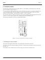
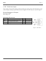
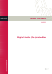
D422
Rev. 6
3. Connector module
The D422 has a dedicated connector module: D422-C1. This module is mounted at the rear of the subrack. The module is shown in figure 2.
To set up a link, two D422 modules must be used. The RS-422 data cable is connected to RS422/E1 on
each of the D422 modules. The two modules are connected to the fibres with one fiber from TX on
module 1 to RX on module 2, and from RX on module 1 to TX on module 2.
The TX UPG connector contains an electrical version of the modulated signal running on the fiber. This
connector is used for future upgrade with a flashlink multichannel DWDM system.
The connector marked E2 is not in use with the D422 module.
Figure 2. Overview of the D422-C1 connector module
3.1 Mounting the connector module.
This section only applies if the module is not purchased pre-mounted in a sub-rack.
The details of how the connector module is mounted, is found in the user manual for the sub-rack frame
FR-2RU-10-2.
This manual is also available from our web site: http://www.network-electronics.com/
6