1
Document type:
User's Manual (MUT)
Title:
Mod. V814 16 Channel Low Threshold Discriminator
Revision date:
06/09/2002
Revision:
3
4. Principles of operation
4.1. Power ON / Reset status
At power ON the contents of all the module’s registers are not determined. A setting of
the registers must be performed before any other operation.
4.2. Enabling/Disabling the channels
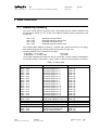
The User can enable or disable each of the 16 channels via VME by performing a VME
write access at Base address + %4A . A channel is enabled if the corresponding bit of the
Pattern of Inhibit is high (e. g., bin. 1111 1111 1111 0011, or hex. FFF3, disables
channels 2 and 3 of the discriminator).
4.3. Enabling/Disabling the channels
The User can enable or disable each of the 16 channels via VME by performing a VME
write access at Base address + %4A. A channel is enabled if the corresponding bit of the
Pattern of Inhibit is high (e. g., bin. 1111 1111 1111 0011, or hex FFF3, disables
channels 2 and 3 of the discriminator).
4.4. Test, Veto and Or signals
Some operations can be performed by sending two external NIM signals:
•
TEST: an input signal sent through this connector triggers all the enabled
channels at once. This feature allows to test of the module as well as to generate
a pattern of pulses suitable to test any following electronics.
•
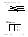
VETO: an input signal sent through this connector allows to veto all channels
simultaneously. A veto pulse of width T will inhibit the input channels for a period
with a T duration. Its leading edge must precede the input signal leading
edge by at least 8 ns and overlap completely the input signal.
Note: TEST and VETO are high impedance inputs and each one is provided
with two bridged connectors for daisy chaining; the chain has to be terminated
on 50 Ohm on the last module; the same is needed also if one module only is
used, whose inputs have thus to be properly matched
NPO:
00101/97:V814x.MUTx/03
Filename:
V814_REV3.DOC
Number of pages:
22
Page:
18