1
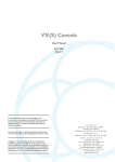
88 Series Outboard / 8816 Summing Mixer
Issue 5
Neve 8816
16:2 Summing Mixer
User Manual
527 - 361
Issue 5
AMS NEVE
Billington Road
Burnley
Lancs
BB11 5UB
England
Phone +44 (0)1282 457011
Fax: +44 (0)1282 417282
[email protected]
www.ams-neve.com
www.neve.eu
- Page 1 -
88 Series Outboard / 8816 Summing Mixer
Issue 5
Health & Safety Notice
For your own safety and for the protection of others please observe
the following safety instructions:
•
Read these instructions.
•
Heed all safety warnings.
•
Do not use near water.
•
Clean only with a dry cloth.
•
Do not install near heat sources.
•
Do not block ventilation openings.
•
Protect the power cord.
•
Only use accessories specified by the manufacturer.
•
Unplug when unused for long periods of time.
•
Refer all servicing to qualified personnel only.
© 2007 AMS Neve Ltd own the copyright of all information and drawings contained in
this manual which are not to be copied or reproduced by any means or disclosed in
part or whole to any third party without written permission.
As part of our policy of continual product improvement, we reserve the right to alter
specifications without notice but with due regard to all current legislation.
Disclaimer: The information in this manual has been carefully checked and is
believed to be accurate at the time of publication. However, no responsibility is taken
by us for inaccuracies, errors or omissions nor any liability assumed for any loss or
damage resulting either directly or indirectly from use of the information contained
within it.
Trademarks: All trademarks are the property of their respective owners and are
hereby acknowledged.
- Page 2 -
88 Series Outboard / 8816 Summing Mixer
Issue 5
Table of Contents
Health & Safety Notice........................................................................................2
1 - Introduction..................................................................................................5
Note on Headroom and Levels......................................................................................5
2 - Application Scenarios.....................................................................................6
Recording..................................................................................................................6
Recording with optional Fader Pack...............................................................................7
Overdubbing..............................................................................................................8
Mixing.......................................................................................................................9
Mixing with Fader Pack..............................................................................................10
Mastering................................................................................................................11
Live Recording.........................................................................................................12
Sub Mixer................................................................................................................13
3 - Controls.......................................................................................................14
Channel Strip.......................................................................................................14
Level Control........................................................................................................14
Pan Control..........................................................................................................14
Cue Control Button...............................................................................................14
Channel Cut /Solo button.......................................................................................14
Cue Section.............................................................................................................15
2T to Cue............................................................................................................15
Headphone Mon...................................................................................................15
Headphone Control...............................................................................................15
Headphone Jack...................................................................................................15
4 - Master Section.............................................................................................16
Alt Spk................................................................................................................16
iMon...................................................................................................................16
Talkback Level.....................................................................................................16
Talkback Microphone.............................................................................................16
INS MIX .............................................................................................................16
IMR Level Control.................................................................................................16
INS.....................................................................................................................16
2TR MIX..............................................................................................................17
2TR Level Control.................................................................................................17
Monitor Selections................................................................................................17
Mon Level............................................................................................................17
Sum....................................................................................................................17
Width Control.......................................................................................................17
<W> button.........................................................................................................17
Mix Level.............................................................................................................18
Analogue / Digital overload indication......................................................................18
Metering..............................................................................................................18
Power Switch.......................................................................................................18
5 - Options........................................................................................................19
Fader Pack Option....................................................................................................19
ADC Option..............................................................................................................19
Sampling Frequency..............................................................................................19
Double Rate AES Output........................................................................................19
DSD....................................................................................................................19
- Page 3 -
88 Series Outboard / 8816 Summing Mixer
Issue 5
6 - Rear Panel Connectors and Controls.............................................................21
Line Output..........................................................................................................21
Line Input............................................................................................................21
Talkback Foot Switch............................................................................................21
USB....................................................................................................................21
Rear Panel Controls..................................................................................................21
Earth Lift Switch...................................................................................................21
Slave Bus Switch..................................................................................................21
ADC Option..............................................................................................................21
ADC Input...........................................................................................................21
AES Sync.............................................................................................................21
WCLK In..............................................................................................................22
WCLK Out............................................................................................................22
AES Out..............................................................................................................22
DSD L and R........................................................................................................22
75 Ohm WCLK......................................................................................................22
SDIF 2/3.............................................................................................................22
7 - Firmware Upgrades......................................................................................23
Selecting a File for Transfer.......................................................................................23
File Downloading......................................................................................................24
Corrupted or Old Firmware........................................................................................24
8 - Physical & Technical Information.................................................................25
Dimensions..............................................................................................................25
Rack Mounting and Cooling........................................................................................25
Power Requirements.................................................................................................25
Mains Supply.......................................................................................................25
9 - System Settings...........................................................................................26
Setting Headroom for Optional A to D.........................................................................26
Fader Pack Jumper Settings.......................................................................................26
Monitor Source pre/post ADC Insert............................................................................27
10 - Unit Specifications.....................................................................................28
11 - Connectors................................................................................................29
12 - Recall Software Installation.......................................................................31
Installation for PC.....................................................................................................31
Installation for Mac...................................................................................................33
-----+-----
13 - Block Diagrams
8816
Optional Fader Pack control
Optional ADC board installation
- Page 4 -
88 Series Outboard / 8816 Summing Mixer
Issue 5
1 - Introduction
The 8816 is an extremely versatile 16:2 summing mixer, which can
produce the highest possible recording and mixing performances in any
format using revered Neve analogue designs including transformer
mixing.
With comprehensive input, mixing and monitoring functions, 8816 can
upgrade a DAW to a professional mixing facility. Not only does the unit
provide quite unbelievable analogue facilities but also has remix and
Recall as standard.
In addition to the superb facilities offered as standard on the 8816
there are two options, digital outputs and a fader pack.
ADC Output
World class A to Ds with sampling rates of up to 192kHz and DSD
outputs. Analogue insert points are provided ahead of the ADCs that
couple the ultimate analogue circuitry with superior digital conversion
making the unit an obvious choice for complete integration with a
DAW.
NOTE: Requires internal fitting, please consult your local Neve dealer.
Fader Pack
16 Input Faders with Cut / Solo controls and post fade direct outputs
plus 2 Master Faders give the engineer fine level control with a
traditional feel. With the fader unit attached, the rotary channel level
controls become aux send levels increasing the functionality of the
unit.
Note on Headroom and Levels
•
Each channel has 15dB of gain also known as 15dB 'in hand'.
•
Excessive use of gain may overload your DAW or other
recording device. 0dB on the channel level control is approx at
the 12’o’clock position.
•
Internal headroom is 26dBu.
•
If your DAW is overloading but the overload indicators on the
8816 meters are NOT illuminated then back off your output
levels.
•
If your DAW is overloading and the red overload indicators ARE
illuminated then you may need to back off your input levels.
- Page 5 -
88 Series Outboard / 8816 Summing Mixer
Issue 5
2 - Application Scenarios
Recording
The 8816 can be used to monitor from the workstation while recording
directly from a mic pre such as the 1073DPD or as a pre-mixer for
recording a number of signals simultaneously to the workstation.
With the optional fader pack, direct outs can be used from the 8816 to
the DAW enabling it to be used like a conventional desk with both
recording and monitoring signals passing through the unit.
Direct recording with 8816 as monitor
Connect the output of the mic pre to the input of the workstation.
Connect the outputs of the workstation to the inputs of the 8816. The
8816 outputs can be monitored on loudspeakers or headphones as
required. The performers headphones source can be switched
(engineer/performer).
Sub-mixing signals to be recorded
Connect the instruments to be recorded to the inputs of the 8816 (via
a 1073 or similar mic pre if required). Connect the main output of the
8816 to the inputs of the workstation (this can be analogue or digital if
the optional digital card is fitted).
Set the balance required using the channel level controls on the 8816
and record onto the workstation.
- Page 6 -
88 Series Outboard / 8816 Summing Mixer
Issue 5
Recording with optional Fader Pack
Connect the instruments to be recorded to channel inputs on the 8816
and connect the direct outputs from these channels to the inputs of the
DAW (the direct outs are located on the fader pack).
These channels can be muted so that they do not go to the main bus if
monitoring via the 8816 or a monitor mix can be set up on the DAW
and monitored via the 2 Track Return on the 8816.
Signals can now be recorded with fader control over their level while
the mix or play back is monitored through the 8816.
In all of the above recording situations the engineer can utilise the
8816 to control monitoring via two pairs of speakers and/or the
headphones as required.
The 8816 can also be used to provide a Cue to performer headphones.
- Page 7 -
88 Series Outboard / 8816 Summing Mixer
Issue 5
Overdubbing
Connect the outputs of the workstation to the inputs of the 8816. If
you have a backing track pre-mix on your workstation assign this to
outputs connected to inputs 15/16 on the 8816.
Connect the output of the track being recorded to any of inputs 1-14
on the 8816.
Connect the performer’s headphones to the headphone socket on the
rear of the 8816.
The cue mix level of the overdub against the backing track can be
adjusted using the Cue level control until the mix is right for the
performer.
The 2-Track Return can also be routed to the Cue so may be used as
an effects return if the performer wishes to listen to a guide reverb
while recording.
The engineer can monitor on headphones connected to the front of the
8816 and can switch between monitoring the performer’s cue mix and
the main mix.
- Page 8 -
88 Series Outboard / 8816 Summing Mixer
Issue 5
Mixing
Connect the outputs of the workstation to the inputs of the 8816. Key
elements such as lead vocals and lead instruments should be kept
separate within the workstation and connected to individual inputs on
the 8816. Other elements such as backing vocals, effects, etc can be
routed to stereo groups within the workstation and these groups
connected to the 8816 inputs.
Optimum sound quality within the workstation is generally achieved by
setting the virtual faders to 0dB. Final mix levels can be set on the
8816.
The mix is now being created on the mix bus of the 8816. This uses
the same transformer mix topology as the classic 80 series Neve
consoles and recreates their legendary sound. Recording back to the
DAW or onto another device such as a CDR may be analogue or, if the
digital option is fitted, can be from the Neve Analogue to Digital
Converters ensuring the best possible sound quality.
A Neve 33609 compressor or a Neve 8803 EQ unit can be patched
across the Insert allowing the whole mix to be compressed or EQ’d.
Sometimes it is necessary to mix between a clean mix and a processed
mix, for example when using a Filter Bank to create a special effect
across the whole mix for one section of a song. This can be done by
patching the filter bank across the Inserts of the 8816 and switching to
Insert Mix mode.
The balance between the clean mix and the processed mix is now
controlled by the Insert Mix level control and the engineer can switch
between clean and processed mix or balance the two as required.
- Page 9 -
88 Series Outboard / 8816 Summing Mixer
Issue 5
Mixing with Fader Pack
The engineer and producer can monitor on two sets of speakers, main
and near field, and switch between them using the Alt Speaker switch
allowing comparisons of the mix on small and large speakers.
Headphones can also be connected if required.
The outputs of the recording unit (or the appropriate two tracks of the
DAW) can be connected to the two track return so that the engineer
can switch between monitoring the mix leaving the 8816 and the mix
coming back from the recorder.
- Page 10 -
88 Series Outboard / 8816 Summing Mixer
Issue 5
Mastering
Connect the outputs of your DAT, CD player or two tracks of your DAW
to inputs 1 and 2 on the 8816. Connect the master outputs of the 8816
to the inputs of the Workstation, CDR or DAT that you wish to record
onto.
Connect the outputs of the recording device to the 2 track return of the
8816.
The mix is now passing through the mix bus of the 8816.
A Neve 33609 compressor or a Neve 8803 EQ unit can be patched
across the Insert Point allowing the whole mix to be compressed or
EQ’d.
The Insert can be switched to Sum and Difference mode allowing the
producer to process the centre sum/mono signal and the
stereo/difference signal in different manners. The width control can be
used to reduce the stereo width, perhaps for a club remix, or to
enhance it beyond standard stereo if the original mix is not wide
enough.
The engineer and producer can monitor on two sets of speakers, and
switch between them using the Alt Speaker switch allowing
comparisons of the mastered mix on small and large speakers.
Headphones can also be connected if required.
The monitor source select can be used to switch between monitoring
the sound entering the 8816 on inputs 1 and 2, the sound leaving the
8816 on the mix bus and the sound as recorded on the
CDR/DAT/Workstation via the 2 Track Return.
- Page 11 -
88 Series Outboard / 8816 Summing Mixer
Issue 5
Live Recording
While the output for the main Front Of House console may be of a high
standard, the mix created for the venue does not have the correct
balance for the recording. The 8816 can solve this problem.
The main mix outputs of the 8816 should be connected to a recording
device such as a DAT or DAW running on a laptop Mac or PC. The
output of the recording device should be connected to the 2 Track
Return on the 8816.
Key elements such as the lead vocal can be connected directly to an
input on the 8816 from a Direct Out on the FOH console. Other
elements such as drums, keyboards, etc can be connected to the
inputs of the 8816 either from the Group Outputs or from the Matrix
Outputs of the FOH console depending on the type of FOH console
being used.
A correct balance between the individual and pre-mixed sounds can be
set up on the 8816 using the Channel level controls. The mix is now
passing through the mix bus of the 8816.
The engineer can monitor the live recording on headphones and switch
between monitoring the output of the 8816 and the 2 Track Return
from the recorder for a confidence check on the recorded sound.
- Page 12 -
88 Series Outboard / 8816 Summing Mixer
Issue 5
Sub Mixer
Sometime the console being used for a mix simply does not have
enough inputs. This may be because it is a small digital mixer being
used to meet a fixed budget or because the console has a limited
number of inputs.
Connect the outputs of the additional instruments or sound sources
such as keyboards, effects units etc to the inputs of the 8816. Connect
the Main Outputs of the 8816 to a pair of inputs on the main mixer.
The sounds passing through the 8816 can be balanced using the
Channel Level controls. These sounds are now passing through the
mix bus of the 8816.
The overall level being passed to the main mixer can be set using the
Master Level control of the 8816.
Should more than 16 inputs be required on the sub-mixer then two
8816 units can be used. The output from the first 8816 is connected to
the 2 Track Bus Input of the second 8816 and the Main Output from
the second 8816 goes to the main mixer.
- Page 13 -
88 Series Outboard / 8816 Summing Mixer
Issue 5
3 - Controls
Channel Strip
The channel strip comprises a Cut/Solo button, a rotary Level
control, a rotary Pan control and a Cue select button.
Level Control
The Level Control has a range of ∞dB to +15dB with 0dB set at about
12 o'clock. This range is deliberately chosen to be able to
accommodate most line inputs levels whether they be professional
+4dBu inputs or semi-professional -10dBV inputs. The Level control
sets the levels going to the main L+R Mix Outputs and to the Utility
Aux Bus with the extra benefit of changing its function into an
individual aux bus send level when an optional fader panel is fitted.
Pan Control
This is a classic -3dB centre pan, with S-Law shaping to help accurate
panning to extremes of left and right.
Cue Control Button
When operated this takes the input of the channel (pre level and pre
pan) and sends it to the cue mixer via the cue level control to feed the
cue output to headphones. Channels 1-14 are individually switchable to
the cue via the Cue level control. Channels 15 and 16 are linked as a
stereo cue direct to the cue mix. For overdubbing, channels 15-16 can
be set up as your backing track mix on the DAW, and then selecting
the appropriate channel from 1 to 14 will allow you to blend or ride a
track using the cue level control, allowing the artist to hear exactly
what he or she needs to hear before dropping in to record.
Channel Cut /Solo button
The function of the button can be changed from Cut to Solo by
operating the Solo Master adjacent to channel 16.
In Cut mode this button will mute the feed to the main two track bus.
Cut is indicated by the button turning red.
In Solo mode, selecting the button will cut all channels except the one
operated, commonly referred to as Solo In Place.
Solo is indicated by the button turning yellow.
As the solo system is latching, it is possible to build up solo groups and
to then use the Cut/Solo Master to audition a solo group or a cut
group.
This can be useful for comping or sorting out EQ / balance problems in
the mix quickly before printing the final pass.
- Page 14 -
88 Series Outboard / 8816 Summing Mixer
Issue 5
Cue Section
2T to Cue
Sends the 2 Track Return (post level control) to the headphone mix –
ideally suited for replaying the last overdub to the artist for auditioning
or a complete 2 track mix of the whole song without the artist needing
to come into the control room.
Headphone Mon
Selects the prefade LS Outputs onto the Cue headphone outputs so
the artist hears the same sources as the engineer feeds to the
monitors.
Headphone Control
This control adjusts the main Headphone levels with a range of ∞dB 0dB.
The headphone control also incorporates a switch which, when
operated, feeds the unit's talkback mic to the Headphone Output,
automatically dimming the music fed to the headphones and
loudspeakers.
There is also a parallel 1/4 inch jack on the rear of the unit for
footswitch operation.
Headphone Jack
A headphone jack is provided on the front of the unit and a second
parallel headphone jack on the rear.
Parallel +4dBu line outputs are provided on the rear of the unit to be
used for Cue feeds to the studio.
NOTE: Only headphones with impedances above 60 Ohms should be used.
- Page 15 -
88 Series Outboard / 8816 Summing Mixer
Issue 5
4 - Master Section
Alt Spk
Selects a second set of loudspeakers for switching between main and
near field loud speakers.
iMon
This input has a 3.5mm jack socket for connecting your iPod or other
MP3 player to the unit’s LS selector and feeding to the LS Output or
Cue headphone outputs.
Talkback Level
This adjustment screw sets the level from the talkback mic to the cue
headphones. This is performed when setting up the unit, so talkback is
at a set level during a session.
Talkback Microphone
A microphone is built into the unit to allow the engineer or producer to
communicate with the artist during recording sessions.
INS MIX
Insert Mix routes the IMR signal to the main 2 Track Mix Output
pre-level control but post-insert.
IMR Level Control
Insert Mix Return allows for the IMR signals to be mixed directly into
the main mix output, post insert but pre mix output level control. It
has a range of ∞dB to +10dB and can be used for DJ style mixing or
where the engineer wants to mix some compressed or EQ’d main mix
source back into the main mix outputs without the compression or EQ
dominating the mix as it would using the insert.
INS
This switches the main mix pre fade insert in and out of circuit via the
input and output connectors on the rear of the unit.
It has two modes selectable by pressing the Mix Level control. When a
normal pre fade insert is selected the button will illuminate yellow.
If the mix level control is pressed then the illumination will change to
red indicating that the insert point has changed to a Sum &
Difference insert.
In Sum and Difference mode the standard stereo signal is converted
into a mono common or sum signal on the left output and a mono
difference signal on the right output.
This enables the engineer to apply different processes to the common
(or centre) image and the difference (or stereo) image.
At the insert return the signal is re-converted to a standard stereo
signal.
The technique is frequently used in mastering recordings and is useful
for:
•
•
•
Using an overall stereo EQ where the L & R Image will not shift
with any tracking errors within the EQ unit, or EQ the mono to
subtly change the mix balance post mixing.
Compress and limit the Sum and Difference separately to
negate tracking errors or create a quite different stereo image.
Add a sub bass synth to the mono program for really deep
mono bass that will not make the cutter head jump if
mastering to vinyl.
- Page 16 -
88 Series Outboard / 8816 Summing Mixer
Issue 5
•
•
Listen to the mono and trim the DAW sample delays to get
perfect L & R tracking and save the results to an interleaved
wav file.
A vocal could be brightened by EQing the Sum signal or
Cymbals could be brightened by EQing the Difference signal.
N.B. The underlying mode of the insert can be changed by pressing the Mix level control even if the
insertion button is not selected.
2TR MIX
When selected, sends the 2 track return signal directly to the 2 Track
Mix bus.
2TR Level Control
This adjusts the two track return level sent to the Cue Mix or 2 Track
Mix bus and has a range of ∞dB to +10dB. This is useful for sending 2
track mixes to the cue headphones or as a reverb return to the cues or
2 track mix bus.
Monitor Selections
There are 3 leds above the Mon level control that indicate what is
selected to the LS monitor.
If no led is illuminated then the main monitor defaults to the main mix
output. Selection of the sources to the monitor is by pressing the Mon
level control.
•
1st press: selects 2TR to Mon
•
2nd press: selects CH1/2 pre fade sources
•
3rd press: selects iMon input
•
4th press: returns the monitor to the Main Mix output.
It is also possible to set the main mix source to the monitors post the
ADC insert jack (if fitted), which will allow for monitoring of the main
mix signal or the inserted signal.
This could be of benefit when you need to monitor the ADC Input which
could be a completely different source from the 8816 such as when
using the digital option as a separate high quality stereo A to D.
NOTE: The monitor source can be set to pre or post ADC insert using jumpers within the unit.
Information is provided in the Jumper Settings section.
Mon Level
This alters the loud speaker’s output level and has a range of ∞dB to
0dB.
Sum
This is selected by pressing the width control. When illuminated yellow
then the main mix outputs are summed with whatever is selected to
the LS Monitor. This function is useful when auditioning mixes
together in the Main or Alt loudspeakers.
Width Control
The Width control is post mix level control, and alters the stereo image
from mono through stereo to enhanced stereo.
<W> button
This switches the Width control into circuit across the Main mix output
(post insert) and is indicated by the button being illuminated yellow.
- Page 17 -
88 Series Outboard / 8816 Summing Mixer
Issue 5
Mix Level
This alters the main mix level and has a range of ∞dB to 0dB. It can be
used to control the output level from the unit to the DAW.
The control can also be augmented with fader control if an optional
fader pack is fitted. In this case, the mix level control no longer has
any function.
Analogue / Digital overload indication
Analogue overload of the unit is indicated by a red led in the associated
left or right output meter. The actual level at which the overload led
illuminates is about 1dB below the max output of the unit (+26 dBu).
If the ADC option is fitted to the unit then the led will light yellow if a
digital overload occurs for more than 1 sample. This has priority over
the analogue overload indication. Sensitivity of the digital overload
indication will be set by the unit’s digital operating level.
Metering
The main left and right meters are sourced directly from the main
outputs so signal problems within the unit or what is connected can be
metered correctly. The meter is a pseudo PPM type with a special scale
that ranges from -16 to +26 dBu. This type of meter and range is ideal
for accurate metering of analogue levels when they are fed to a digital
recorder to maximise levels and to avoid digital clipping. Three
important points are identified on the meter to help the user to match
levels between the unit and a DAW.
•
•
•
0 (PPM Scale Point 5) for line-up +4dBu (0vu)
14 (PPM Scale Point 8.5) +18 dBu for typical DAWs set to 14 = 0dBFS, REL +4 dBu.
18 (PPM Scale Point 9.5) +22 dBu for typical DAWs set to 18 = 0dBFS, REL +4 dBu.
Power Switch
Switches the unit on/off and indicates a healthy +36 volts supply by
illuminating red.
- Page 18 -
88 Series Outboard / 8816 Summing Mixer
Issue 5
5 - Options
Fader Pack Option
The optional fader pack provides 16 Input faders with post fade direct
outputs plus mutes and 2 Master faders.
The Input faders have a range of -∞dB to +15 dB.
The Master faders have a range of -∞dB to 0dB.
With the fader pack fitted, the rotary channel level control of the 8816
becomes an aux send level control with a range of -∞dB to +15dB.
This can be used to send channels to a reverb or other effects unit.
Recall of the faders and mutes can be stored using USB and the Recall
application so that they can be included into the multi- unit Recall
system provided on the 88 outboard range.
NOTE: Internal jumper settings must be changed to enable the optional fader pack to take control of the
main mix level. See section on Jumper settings.
•
When the fader option is not fitted, the jumper sets the Aux output level to –3dBu.
•
When the fader option is fitted, the jumper sets the Aux output level to 0dBu
ADC Option
Sampling Frequency
Sample frequency can be selected by pressing the button to the right
of the sample frequency leds. This will toggle through the sampling
frequencies required one at a time.
The 8816 has 2 sync inputs, AES 3 on a female XLR and Word Clock on
a chassis BNC. If neither sync input is present, the unit will synchronise
to its internal crystal clock.
If one or the other sync inputs is present at the correct sampling
frequency the led (AES or WCLK) will illuminate showing that the sync
input is being used as a reference. If both sync inputs are present and
correct the word clock input will be used as the reference.
Normally the sync input is set to the required sample rate. In this case
both AES out 1/L and AES out 2/R carry the same stereo AES signal
converted from the unit’s left and right analogue outputs.
Double Rate AES Output
It is also possible to select 96kHz (or 88.1kHz) sample rate with a
48kHz (or 44.1kHz) sync input. Similarly it is possible to select 192kHz
(or 176.2 kHz) sample rate with a 96kHz (or 88.1kHz) sync input.
This will cause the unit to output double rate AES on the two AES
Output connectors. The sync led will illuminate green indicating the
sync reference is still being used for the digital output even though the
ADC is sampling at twice the sync input sampling rate.
In this situation AES out 1/L carries the odd and even samples of the
left audio double rate signal on its left and right digital channels
respectively. Similarly, AES out 2/R carries the odd and even samples
of the right audio double rate signal on its left and right AES channels.
DSD
Selecting DSD will default to 44.1kHz reference.
If no sync is available it will use its own internal crystal reference. The
- Page 19 -
88 Series Outboard / 8816 Summing Mixer
Issue 5
interface requires a minimum of 2 BNC cables (DSD left and DSD right)
to the DSD recording device. The DSD output is switchable between
SDIF 2 and SDIF 3 with a rear panel switch. SDIF 2 requires a 44.1kHz
sync signal to be passed to the DAC and this should preferably come
from the 8816 sync output via a 3rd BNC cable. SDIF 3 transmits the
DSD signals with clock information included and should not need the
sync signal.
N.B. Refer to your DSD recording device for information on compatibility.
- Page 20 -
88 Series Outboard / 8816 Summing Mixer
Issue 5
6 - Rear Panel Connectors and Controls
Line Output
DB 25 Socket (standard Pro Tools and DA88TM connection) balanced at
+4 dBu for INS, Main and LS Outputs and 1/4 inch stereo jacks at
-10dBv for Main and Alt (Loudspeaker) Outputs.
Line Input
•
•
DB 25 Socket (standard Pro Tools and DA88TM connection)
balanced at +4dBu.
DC Power Input 8 Pin DIN Socket
Talkback Foot Switch
1/4 inch mono jack.
USB
Type B male.
When connecting the unit to a PC (or Mac), it must be connected
directly to an available USB port or via a powered hub, not via a
passive hub.
Rear Panel Controls
Earth Lift Switch
This will lift the mains earth connection from the chassis of the unit,
allowing for the unit to be connected to a suitable technical earth
system thus avoiding hum loops.
Slave Bus Switch
This switches the 2T bus input onto the unit’s main mix bus. This
allows two 8816 units to be joined together to create a slave and
master system expanding the number of inputs. It also automatically
sets the unit to be part of the Recall system as the slave or master.
ADC Option
ADC Input
1/4 inch jack acting as a switched insert into the ADC input. Maximum
input level +26dBu for conversion to 0dBFS.
N.B. See Headroom Level Setting for different input level
conversions.
AES Sync
Female XLR to take a standard AES 110 Ohm input signal for use as a
word clock sync source.
- Page 21 -
88 Series Outboard / 8816 Summing Mixer
Issue 5
WCLK In
BNC input for TTL level world clock signal.
Input impedance can be set to 75 Ohm using the selection switch on
the rear of the unit.
WCLK Out
BNC 75 Ohm output TTL level world clock signal at sampling
frequencies buffered from ADC sync source.
AES Out
Male XLR outputs standard AES 110 Ohm digital audio.
DSD L and R
BNC 75 Ohm output TTL level DSD signal.
75 Ohm WCLK
Selects a 75 Ohm input impedance for WCLK in.
SDIF 2/3
Selects DSD Output format; SDIF2 DSD data only, SDIF3 DSD data
with embedded clock.
- Page 22 -
88 Series Outboard / 8816 Summing Mixer
Issue 5
7 - Firmware Upgrades
In order to get the most from your Neve unit, the latest firmware
should be installed.
Upgrading your software is a simple process with on screens
prompts to guide you.
•
•
•
•
Start the Recall software.
On the main screen, right-click the window title bar (Mac
users select Recall)
Click Upgrade Firmware.
Select the file to transfer.
You will be prompted about removing other units.
When updating units, only the unit that is being updated should
be connected via USB.
All other units should have their USB disconnected. Even if you
are updating two units of the same model, they should be
connected individually and updated in two separate operations.
If more than one unit is connected via USB when the Update is
about to be performed, a screen will prompt you to disconnect
the other units.
A prompt screen will confirm the software number & version you
should select, and display the current version of firmware for the
unit.
Click OK.
Selecting a File for Transfer
The Open File dialog will appear. To locate the firmware data file,
browse to the location:
•
•
PC users: C:\Program Files\Neve Recall\Firmware
Mac users: Applications\Neve Recall\Firmware
The file names follow the format down_88XY_V.hex where XY are
the last two digits of the 88 unit name (e.g. 16 for 8816) and V is
the software version number.
A typical filename could be down_8804_5.hex.
Double click on the latest filename which matches your unit. If an
incorrect file is selected the user will be prompted to select another
file.
- Page 23 -
88 Series Outboard / 8816 Summing Mixer
Issue 5
File Downloading
Once the file is selected the transfer will begin, and the Recall
screen will display that the upload is under way.
This process may take up to two minutes.
Upon completion, the message Firmware Update Successful will
be displayed.
Click OK to continue.
You can continue to update other units successfully without
restarting Recall, but the Recall software must be restarted once
this process is finished.
If the transfer fails (for example if the USB is removed by accident
or power is lost to the unit), a warning message will prompt to the
user to try again.
If Recall is started with a unit that has no firmware, the user will be
prompted to upgrade the firmware, as the unit cannot be used in
Recall unless the firmware installation is successful.
Corrupted or Old Firmware
If the firmware is corrupted or the unit has an old version of
firmware, a prompt will appear upon starting the Recall software to
indicate that firmware must be updated before the user can
proceed.
The process described above can then be followed to update the
latest firmware.
- Page 24 -
88 Series Outboard / 8816 Summing Mixer
Issue 5
8 - Physical & Technical Information
Dimensions
Unit name
Unit Depth
Depth
mm / inches
Height
mm / inches
Weight
kg / lbs
8816
2
390 / 15.4
88 / 3.5
7 / 16
Rack Mounting and Cooling
The rack unit can be installed in a standard 19“ cabinet with access to
the front and the rear.
No specific air conditioning is required for the rack providing there is
free flow of air through the rack from front to back and side to side,
and that the ambient air is maintained below 25 degrees centigrade.
Racks may be stacked, but at least 1U space should be allowed
between each unit.
Power Requirements
8816
Rated Voltage
36v DC
Rated Current
1.6A Max
Primary Protection Fuse:
Operating Voltage
36v
Fuse Rating & Type
T3. 15A anti-surge 20mm x 5mm glass
Location
Next to DC input on rear of unit
Mains Supply
The power supply unit is a free standing external type with a universal
input, therefore no mains operating voltage setting is required.
There is a mains earth lift switch located at the rear of the unit next to
the fuse holder.
When operated this isolates the mains earth from the chassis of the
unit. If this is operated, earth must be maintained to the chassis of the
unit by using the studio technical earth or equivalent earthing system.
When illuminated the red led on the power switch indicates a healthy
+36V supply.
- Page 25 -
88 Series Outboard / 8816 Summing Mixer
Issue 5
9 - System Settings
Setting Headroom for Optional A to D
The unit can be set to one of three headroom settings; +14dB, +18dB
or +22dB relative to +4dBu.
The headroom set is the number of dBs above +4dBu before the ADC
clips.
The clip led within the left and right output meter will come on if the
selected input level is exceeded for more than 1 sample. The headroom
can be changed by accessing the switches through the holes marked
HR, +18 UP or +14 DN (down)
+14 dB
Both switches in the down position.
+18 dB
HR switch down, and +18 & +14 up.
+22 dB
HR, +18 and +14 all up.
NB: Only use a non metallic plunger tool to operate the level change switches.
Fader Pack Jumper Settings
NOTE: Internal jumper settings must be changed to enable the optional
fader pack to take control of the main mix level.
Please consult your local Neve dealer if the following information is not
clear.
- Page 26 -
88 Series Outboard / 8816 Summing Mixer
Issue 5
Monitor Source pre/post ADC Insert
NOTE: The monitor source can be set to pre or post ADC insert using
jumpers within the unit.
Please consult your local Neve dealer if the following Information is not
clear.
- Page 27 -
88 Series Outboard / 8816 Summing Mixer
Issue 5
10 - Unit Specifications
Input Impedance
(Balanced +4dBu) >20 ko's
Output Impedance
(Balanced +4dBu) 50 Ohms
(Unbalanced +4dBu) 100 Ohms
Headphone Jack Output
Impedance Loading
More than 60 Ohms
Max Input Level
(Balanced) Better than +26 dBu
Max Output Level
(Balanced) Better than +26 dBu into 600 Ohms
(Unbalanced) Better than +26 dBu into 600 Ohms
Frequency Response:
Ch 1 Line input to Main Output
20 Hz to 20 kHz +/- 0.5dB
Better than -3dB @ 60k
THD:
Ch 1 Line input to Main Output
50 Hz to 20 kHz, Better than 0.02%
Measured at +20 dBu into 10k with 80k filter.
Noise:
No channels routed
Better than -86 dBu
1 channel routed
Better than -85 dBu
16 channels routed
Better than -80 dBu
20 Hz to 20 kHz filter
All specifications with no processing in circuit
- Page 28 -
88 Series Outboard / 8816 Summing Mixer
Issue 5
11 - Connectors
There are five 25-way D-type connectors.
•
•
•
•
Connectors 1 and 2 for Channel Inputs
Connector 3 for Auxiliary Outputs
Connector 4 for Master section Input
Connector 5 for Master section Outputs.
The 16 line inputs are on 2 x 25way D type connectors and follow the
standard pin-outs used by Pro Tools & Tascam DA88. Connector 1 for
Channel Inputs 1 – 8; connector 2 for Channel Inputs 9 – 16
Circuit
Shield
Hi
Lo
1
25
24
12
2
11
10
23
3
22
21
9
4
8
7
20
5
19
18
6
6
5
4
17
7
16
15
3
8
2
1
1
The same pin arrangement is used on Connectors 3, 4 & 5 to provide
the following circuits:
Connector 3
8
Pre Fade Insert Left Send
7
Pre Fade Insert Right Send
6
Insert Mix Left Send
5
Insert Mix Right Send
4
Aux Bus Send
3
-
2
-
1
-
Connector 4
8
Pre Fade Insert Left Return
7
Pre Fade Insert Right Return
6
Insert Mix Left Return
5
Insert Mix Right Return
4
2 Track Left Return
3
2 Track Right Return
2
2 Track Left Bus Input
1
2 Track Right Bus Input
- Page 29 -
88 Series Outboard / 8816 Summing Mixer
Issue 5
Connector 5
8
Main Mix Left Output
7
Main Mix Right Output
6
Monitor Main Speaker Left Output
5
Monitor Main Speaker Right Output
4
Monitor Alternate Speaker Left Output
3
Monitor Alternate Speaker Right Output
2
Cue Left Output
1
Cue Right Output
There are two unbalanced mono ¼” jack outputs:
Main Mix L & R
Tip
Hi
Sleeve
Screen
There are four unbalanced mono ¼” jack outputs:
Main SPK L & R and
ALT SPK L & R
Tip
Hi
Sleeve
Screen
There are two unbalanced stereo ¼” jack outputs:
L & R Cue &
Headphone
Tip
Left
Ring
Right
Sleeve
Common
There is one unbalanced 3.5mm stereo jack:
iMon
Tip
Left
Ring
Right
Sleeve
Common
There is one control 1/4” jack:
Talkback footswitch
Tip
Control
Sleeve
Common
- Page 30 -
88 Series Outboard / 8816 Summing Mixer
Issue 5
12 - Recall Software Installation
Neve Recall software allows settings from the 8816 to be stored on
a PC or Mac and recalled for later use. Recall can be used for all the
units in the 88 range including 8801, 8803, 8804 and 8816.
Multiple units can be stored and recalled together.
Please see the separate Recall Manual for further details.
This may be downloaded from the Neve web site at
http://www.ams-neve.com/html/downloads/index.php
Installation for PC
Insert the CD into the drive and the Setup program should
automatically launch.
If the application fails to launch automatically, go to the CD drive in
Windows Explorer and double-click the NeveRecall.msi file (or the
setup.exe file) to launch the Setup program manually.
The Welcome screen will launch. Click Next.
Click Next.
Click I Agree, then click Next.
If you click I Do Not Agree, the install procedure will terminate.
The installation programme will automatically select a location for
all files to be copied to.
Click Next, or click Browse to select another location.
- Page 31 -
88 Series Outboard / 8816 Summing Mixer
Issue 5
Click Next to start the installation.
The install will start and the installation progress will be shown.
Click Next.
Once the install has successfully completed, click Close.
The software will now be ready to use, and will be accessible from
Start Menu / Programs / Neve Recall / Neve Recall, or from
the Recall icon on the Desktop.
- Page 32 -
88 Series Outboard / 8816 Summing Mixer
Issue 5
Installation for Mac
Insert the CD containing the software into the Mac, and the install
programme will launch automatically.
Click Continue.
Select the location where you wish the software to be installed to.
Click Continue.
Click Upgrade, and the software will start to install.
The progress bar will show the state of the installation.
Once completed, click Close.
The software is now ready to use.
- Page 33 -