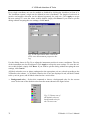
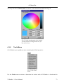
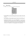
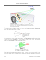
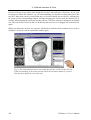
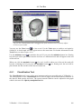
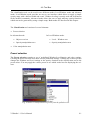
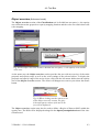
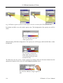
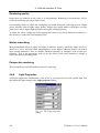
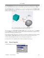
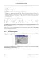
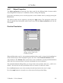
1
VGStudio 1.1
Volume Graphics GmbH
Wieblinger Weg 92a
D-69123 Heidelberg
Germany
Tel: +49 / 6221 / 73920 60
Fax: +49 / 6221 / 73920 88
Printed in Germany. First printing, July 1999.
© 1999-2001, Volume Graphics GmbH. All rights reserved. VGL is a trademark of Volume
Graphics GmbH.
The VGStudio software described in this manual is provided under license. The software may be
used or backed up only in accordance with the terms of the agreement. Information in this document is subject to change without notice and does not represent product specification or commitment on the part of Volume Graphics. No part of this publication may be reproduced,
transmitted, transcribed, stored in a retrieval system, or translated into any language in any form
without the express, written permission of Volume Graphics GmbH.
All product names mentioned in this manual are used for identification purposes only and may
be trademarks or registered trademarks of their respective companies. Registered and unregistered trademarks used herein are the exclusive property of their respective owners. Volume
Graphics GmbH makes no claim to any such marks, nor willingly or knowingly misuses or misapplies such marks.
The information provided in this manual is for reference and informational use only, and Volume
Graphics assumes no responsibility or liability for any inaccuracies or errors that may appear in
this documentation.
Reach us on the Internet:
e-mail: [email protected]
world wide web: http://www.volumegraphics.com
2
VGStudio 1.1 User’s Manual
VGStudio 1.1
Solutions about Voxels
VGStudio 1.1 User’s Manual
3
VGStudio 1.1
Table of Contents
1
Introduction to VGStudio 1.1.............................................................................................11
1.1
Volume Graphics and VGStudio 1.1 ......................................................................................................... 12
1.2
Example Images Rendered by VGStudio 1.1 Users ................................................................................. 13
1.3
About this Manual ...................................................................................................................................... 14
1.4
Conventions Used in this Manual .............................................................................................................. 15
1.5
Where to Get Additional Help ................................................................................................................... 16
1.6
Feedback...................................................................................................................................................... 17
2
Installation ...........................................................................................................................19
2.1
System Requirements ................................................................................................................................. 20
2.2
VGStudio 1.1 on Multiprocessor Hardware............................................................................................. 21
2.3
Installation Instructions ............................................................................................................................. 23
2.4
VGStudio 1.1 License ................................................................................................................................. 24
2.5
Registering VGStudio 1.1........................................................................................................................... 25
3
Getting Started ....................................................................................................................27
3.1
Launching the Program ............................................................................................................................. 28
3.1.1
3.1.2
3.2
Keyboard Usage....................................................................................................................................... 29
Mouse Usage............................................................................................................................................ 31
First Steps with VGStudio ......................................................................................................................... 34
3.2.1
3.2.2
3.2.3
Voxel Objects, Polygon Objects, and Scenes........................................................................................... 47
The Illumination Model ........................................................................................................................... 50
VGStudio Clipboard ................................................................................................................................ 51
3.3
Exiting VGStudio........................................................................................................................................ 52
3.4
Image Quality versus Speed....................................................................................................................... 53
4
VGStudio Interface & Tools...............................................................................................55
4
VGStudio 1.1 User’s Manual
VGStudio 1.1
4.1
Basic Concepts of the VGStudio User Interface.......................................................................................56
4.1.1
4.1.2
4.1.3
2D slices and 3D images ..........................................................................................................................56
VGStudio Color Coding ...........................................................................................................................56
Tool tips ...................................................................................................................................................57
4.2
Title Bar Elements.......................................................................................................................................58
4.3
Menu Bar .....................................................................................................................................................59
4.3.1
4.3.2
4.3.3
4.3.4
4.3.5
4.3.6
4.3.7
4.3.8
4.4
Icon Bar........................................................................................................................................................78
4.4.1
4.4.2
4.4.3
4.4.4
4.4.5
4.4.6
4.5
Standard Icon Section...............................................................................................................................78
Object Manipulation Section....................................................................................................................81
Scene Utilities ..........................................................................................................................................87
View Selection .........................................................................................................................................90
Window Layout Section ...........................................................................................................................91
“What‘s this” Section ...............................................................................................................................92
The Workspace............................................................................................................................................93
4.5.1
4.5.2
4.5.3
4.6
Slice Windows and Multiplanar Reformatting .........................................................................................94
3D Window ............................................................................................................................................100
World and Camera View ........................................................................................................................103
Tool Box .....................................................................................................................................................107
4.6.1
4.6.2
4.6.3
4.6.4
4.6.5
4.6.6
4.6.7
4.6.8
4.6.9
4.7
5
File Menu .................................................................................................................................................59
Edit Menu.................................................................................................................................................62
Setting Preferences ...................................................................................................................................64
Object Menu.............................................................................................................................................67
Scene Menu ..............................................................................................................................................70
Tools Menu ..............................................................................................................................................73
Window Menu..........................................................................................................................................75
Help Menu................................................................................................................................................76
Classification Tool .................................................................................................................................109
Scene Tree ..............................................................................................................................................133
Render Properties ...................................................................................................................................138
Light Properties ......................................................................................................................................140
Stereo Properties ....................................................................................................................................141
Polygon Properties .................................................................................................................................142
Object Properties ....................................................................................................................................143
World View ............................................................................................................................................150
Camera View..........................................................................................................................................152
Status Bar...................................................................................................................................................155
Importing & Exporting Data........................................................................................... 157
5.1
5.1.1
5.1.2
5.1.3
5.1.4
5.1.5
5.1.6
Importing Data ..........................................................................................................................................158
The VGI - Volume Graphics Info - file..................................................................................................158
Importing Stacks of Image Slices...........................................................................................................161
Importing Raw Volume Data .................................................................................................................173
Importing HDF Data ..............................................................................................................................183
Importing ANALYZE™ Data................................................................................................................184
Importing DICOM Data .........................................................................................................................184
VGStudio 1.1 User’s Manual
5
VGStudio 1.1
5.1.7
5.2
Exporting Data.......................................................................................................................................... 187
5.2.1
6
Importing Polygon Data......................................................................................................................... 186
Exporting Raw Volumes ........................................................................................................................ 187
Appendix ............................................................................................................................191
6.1
VGStudio 1.1 and memory consumption................................................................................................ 192
6.1.1
6.1.2
6.2
Memory consumption of voxel data ...................................................................................................... 192
Rendering large high quality images...................................................................................................... 192
Limitations and Known Bugs .................................................................................................................. 193
7
Index ...................................................................................................................................195
6
VGStudio 1.1 User’s Manual
VGStudio 1.1
WELCOME TO VGSTUDIO 1.1 USER’S MANUAL
VGStudio 1.1 is a highly sophisticated image analysis and visualization software and was developed to provide the user with a powerful but easy-to-use interface to process and visualize
voxel/volume data with high-performance analyzing and volume rendering algorithms. It uses an
intuitive graphical user interface (GUI) with standard functions which are well known by most
users from many other software packages. Apart from volume data analysis, VGStudio 1.1 may
also be used for documentation and presentation purposes. You may render high quality images
of the data set under investigation.
We hope you enjoy working with VGStudio 1.1!
All terms you might be unfamiliar with here will be explained throughout this manual.
VGStudio 1.1 User’s Manual
7
VGStudio 1.1
Medical Use Restrictions
We wish to thank you for your past support and continued usage of the
VGStudio voxel data visualization and analysis program. We have many
future plans for the product, and we will advise you through the appropriate channels as these enhancements become available.
At the same time, however, we wish to remind you that the VGStudio
products are "for research use only" or "for investigational use only." The
Department of Health and Human Services (DHHS) National Institute of
Health (NIH) defines "research" as...
" ... a systematic investigation, including research development, testing
and evaluation, designed to develop or contribute to generalizable
knowledge... " (Cf. 45 CFR 46.102(d))
The "human subject" in research is...
" ... a living individual about whom an investigator... conducting research
obtains (1) data through intervention or interaction with the individual, or
(2) identifiable private information. Intervention includes both physical
procedures by which data are gathered and manipulations of the subject
or the subject’s environment that are performed for research purposes.
Interaction includes communication or interpersonal contact between the
investigator and subject... " (Cf. 45 CFR 46.102(f))
Similarly, the DHHS Food and Drug Administration (FDA) defines an "investigation" as... "... a clinical investigation or research involving one or
more subjects to determine the safety or effectiveness of a device... "
(Cf. 21 CFR 812.3(h))
The FDA definition of a "subject" is...
" ... a human who participates in an investigation, either as an individual
on whom... an investigational device is used or as a control. A subject
may be in normal health or may have a medical condition or disease... "
(Cf. 21CFR.812.3(p))
Within this regulatory framework, then, a clinical investigation can be argued to be a more restrictive form of research, in which the data and information collected are intended to be used to support the claims of a
device's safety or effectiveness (the FDA regards software used in medical applications to be a medical device).
At the present time, Volume Graphics makes no representation that the
VGStudio product is either safe or effective for any intended use for
which research may currently be performed.
If you are conducting research or clinical investigations, by law, you are
required to obtain prior Investigational Review Board (IRB) approval of
8
VGStudio 1.1 User’s Manual
VGStudio 1.1
the clinical study protocol and of the patient informed consent documents, and to provide each patient/subject with a copy of the completed
informed consent document. Similarly, if you are conducting research or
clinical investigations using animal subjects, you are obligated to follow
Good Laboratory Practices, and to observe the ethical treatment of the
animals. If your facility or academic institution receives funding from NIH,
or if your IRB has DHHS- approved assurances on-file, then you are obligated to follow the NIH rules, in addition to the FDA rules.
As a consequence of the regulatory status of the VGStudio products, you
are reminded of the Login Acceptance Screen, reprinted below, in which
you acknowledge the regulatory status of the product prior to using its
functionality:
Disclaimer: VGStudio IS NOT FOR CLINICAL USE
VGStudio or data derived from VGStudio may be used only for research
and may not under any circumstances be used for clinical purposes.
Pressing the 'Accept' during the VGStudio installation procedure indicates your consent NOT to use VGStudio for anything other than research purposes.
You are encouraged to contact your governing IRB or clinical risk manager should you have any additional questions or concerns. We hope
that this information clarifies your understanding of the regulatory status
of the VGStudio product, and look forward to continued dialog with you.
To acknowledge the conditions regulating the use of VGStudio, please
sign this letter in the space provided below and fax a copy of page 8 and
9 to us at +49 621 181 2634.
We wish you continued success in your research activities.
—
Volume Graphics GmbH
I agree to the above restrictions on the use of VGStudio.
_________________________________
Customer's Signature
_________________________________
Customer's Name (Printed)
_________________________________
Organization
VGStudio 1.1 User’s Manual
9
1 Introduction to VGStudio 1.1
This chapter will help the user in getting accustomed with the program and its functions, and
gives an overview of some basic concepts the user should keep in mind when using the program.
This chapter covers the following topics:
•= Volume graphics and VGStudio
•= About this manual
•= Conventions used in this manual
•= Where to get additional help
•= Where to send feedback
1. Introduction to VGStudio 1.1
1.1 Volume Graphics and VGStudio 1.1
Volume rendering or, to use a more general term, volume graphics, is a sub-specialty of 3D
computer graphics which deals with the discrete representation and visualization of objects represented as sampled data in three or more dimensions. Volume graphics differs from traditional
3D graphics in that 3D graphics primarily deals with the representation of object surfaces,
whereas volume graphics deals with the representation of both object surfaces and interiors. In
volume graphics, for example, sample points such as CT or MRI scans are taken from the real
world, assigned color and transparency levels, and are then projected directly onto the computer
screen.
Fig. 1 Color and transparency levels are assigned to CT or MRI scans and are then projected
directly onto the computer screen.
In recent years, the popularity of volume graphics has grown considerably. A few years ago,
volume graphics was still limited by the large amount of computational power and memory required for real-time volume rendering. In contrast to classical or advanced 2D image processing,
volume visualization and analysis produces huge amounts of data, so that memory, processor
performances and algorithms are critical. Due to the highly sophisticated algorithms used in
VGStudio 1.1 and the increase in PC computing power, volume graphics and volume analysis
became accessible to everybody as the program runs on a standard PC. The adoption of efficient
solutions in VGStudio 1.1, e.g. the multiprocessor (SMP) capable implementation of nearly
every VGStudio 1.1 feature, allows the user to apply a trial and error approach to the analysis of
3D data; the user can apply an operation or a transformation to the data and control the result in
an interactive and real-time environment, and may thus select the best suited operation for
his/her needs. By using VGStudio 1.1, everybody can take advantage of volume graphics technology which has inherent advantages for applications that need visualization of irregular objects, or where the interior structure and a high-quality detail representation are essential, e.g.
representations of the human body.
12
VGStudio 1.1 User’s Manual
1.2 Example Images Rendered by VGStudio 1.1 Users
1.2 Example Images Rendered by VGStudio 1.1 Users
Fig. 2 Here are example images rendered by VGStudio users.
VGStudio 1.1 User’s Manual
13
1. Introduction to VGStudio 1.1
1.3 About this Manual
VGStudio has been designed to be as intuitive as possible, but as it is a sophisticated program,
you might need help from time to time. In this case, you should refer to this manual which includes a comprehensive table of contents and an index to help you find the information you need.
This manual assumes that you are familiar with the Unix or Windows operating systems. If you
need help with features specific to either system, please refer to the documentation supplied with
your computer.
14
VGStudio 1.1 User’s Manual
1.4 Conventions Used in this Manual
1.4 Conventions Used in this Manual
This manual uses the following conventions to identify information:
•= Whenever you must execute a command by clicking the mouse, the command will be displayed in bold text (for example, click OK to continue).
•= Menu items and buttons also appear in bold text for easy identification (for example, the File
menu or the Save button).
•= You will find the following icons throughout the manual. The icons indicate which mouse
button you should press to execute the appropriate action.
Press left mouse button
Press middle mouse button
Press right mouse button
•= Throughout the manual, you will find Reminder icons. They indicate important facts and
exceptions.
•= Chapter cross references are displayed in italics (for example, Chapter 1, Introduction).
•= This manual combines Windows and Unix instructions. In most cases, they overlap, but in
those instances when there are differences (most often with key commands), the manual will
list both commands.
VGStudio 1.1 User’s Manual
15
1. Introduction to VGStudio 1.1
1.5 Where to Get Additional Help
Check the table of contents or the index whenever you need to locate information on a particular
function. If you cannot find the information, there are other ways to get help. Please also refer to
Chapter 2.5 Registering VGStudio 1.1.
•= Installation & Information Card—Provides latest information on the current VGStudio 1.1
release and information on the installation procedure for your operating system.
•= Volume Graphics Web Site—The Internet is a quick way to get answers to your questions.
You can use the Volume Graphics web site at www.volumegraphics.com as a technical support resource.
•= E-Mail— Send an e-mail to Volume Graphics at [email protected]
•= Volume Graphics Technical Support—If none of the resources mentioned above provides
the answer, you can contact the Volume Graphics technical support by sending an e-mail to
[email protected] or one of our sales representatives. Please be at your computer and have your registration number available when you call.
•= Volume Graphics Sales—Our friendly and knowledgeable sales personnel can answer basic
questions about product capabilities and give information on other Volume Graphics products which may fit your needs. You may contact our sales department by sending an e-mail
to [email protected] or one of our sales representatives.
16
VGStudio 1.1 User’s Manual
1.6 Feedback
1.6 Feedback
We are very interested in your comments on VGStudio. Many of VGStudio's changes and improvements over the years were based upon user requests and input. If you have comments or
feature requests, please send them to us via the World Wide Web:
http://www.volumegraphics.com
e-mail: [email protected]
You may also send a letter or fax to the following address / fax number:
Volume Graphics GmbH
VGStudio Product Manager
Wieblinger Weg 92a
D-69123 Heidelberg
Germany
Tel: +49 / 6221 / 73920 60
Fax: +49 / 6221 / 73920 88
VGStudio 1.1 User’s Manual
17
1. Introduction to VGStudio 1.1
18
VGStudio 1.1 User’s Manual
2 Installation
This chapter gives general information on installation requirements and on the installation itself.
Each section provides the users with instructions for both Windows and Unix operating systems.
Find the section that is appropriate for your operating system.
This chapter covers the following topics:
•= System requirements
•= Installation instructions
•= Registering VGStudio
2. Installation
2.1 System Requirements
This section lists the minimum system requirements for Windows and Unix users. Refer to the
section that is appropriate for you. Also, see the section on VGStudio and memory usage in the
Appendix.
Windows
Microsoft Windows™ 9x, Windows NT 4.0 or Windows 2000 operating system
Pentium III or higher or equivalent CPU
64 MB RAM (128 MB or more recommended)
Super VGA display (17" or larger recommended) with 800x600 resolution and 256 colors
(1280x1024 at High Color recommended)
CD-ROM drive
Unix
Linux 2.0 (other Unix OS on request) operating system
64 MB available RAM (128 MB or more recommended)
Super VGA display (17" or larger recommended) with 800x600 resolution and 256 colors
(1280x1024 at High Color recommended)
CD-ROM drive
20
VGStudio 1.1 User’s Manual
2.2 VGStudio 1.1 on Multiprocessor Hardware
2.2 VGStudio 1.1 on Multiprocessor Hardware
Almost all features included in VGStudio 1.1 are implemented multithreaded so that VGStudio
1.1 takes full advantage of modern processor technologies. Especially on multiprocessor (SMP)
hardware, VGStudio 1.1 delivers an almost linear speedup proportional to the number of processors in use. VGStudio 1.1 utilizes the full memory bandwidth of today’s and upcoming system
designs to provide its users with an optimal performance.
By default VGStudio 1.1 utilizes all processors available in a system. The user may limit the
number of processors used by VGStudio 1.1 by applying the environment variable PROCESSORS with the appropriate number of processors.
Adding environment variables on a Windows NT 4.0 / 2000 System
Step 1: Choose Settings in the Program Manager Start menu.
Step 2: Choose Control Panel from the Settings menu.
Step 3: Double-click the System icon to display System Properties.
Step 4: On the Environment index card, click any existing variable name in the list you want to
add the variable to.
Step 5: Type in the name of the new variable in the Variable box.
Step 6: Type in the value in the Value box.
Step 7: Click Set.
Notes:
If you are not an administrator, you may add variables only to the User Variables list. Windows
NT will save changes in the registry so that they will be available automatically the next time
you start your computer. Changes will not affect programs that are running, and will only be
effective once you have restarted your computer.
Adding environment variables on a Unix system
Examples for utilization of 2 processors.
For tcsh users type:
setenv PROCESSORS 2
For bash users type:
export PROCESSORS=2
VGStudio 1.1 User’s Manual
21
2. Installation
Notes:
Ask your system administrator for help if you are not familiar with modifying system or environment variables. To modify your PATH variable, type in one of the following commands depending on what shell you use and where you have installed the software. Include the
corresponding line into your .cshrc or your .bashrc file if you do not want to modify your environment variables every time you log into your system.
22
VGStudio 1.1 User’s Manual
2.3 Installation Instructions
2.3 Installation Instructions
Please refer to the Installation & Information Card which is supplied with your VGStudio 1.1
software package for up-to-date and detailed information on the installation procedure for your
operating system. It also provides you with the latest information on the current VGStudio 1.1
release.
VGStudio 1.1 User’s Manual
23
2. Installation
2.4 VGStudio 1.1 License
The VGStudio 1.1 License update window will pop up when you start VGStudio 1.1 for the
first time or when no valid license was found on your system. Enter your name or the name of
your company and the license key which is included in your VGStudio 1.1 software package and
click OK. You may also ask the Volume Graphics support for a trial license at [email protected]. To do so press the Create registration form button, fill in the required information and send the registration form to Volume Graphics. See Chapter 1.6
Feedback for more information on how to contact Volume Graphics directly.
Fig. 3 The License update window where you enter
your name and license key.
24
VGStudio 1.1 User’s Manual
2.5 Registering VGStudio 1.1
2.5 Registering VGStudio 1.1
To be eligible for technical support, as well as receive information on bug-fix updates and feature upgrades, you must register your copy of VGStudio. To register press the Create registration form button in the License dialog (please refer to Chapter 4.3.8 Help Menu License
update), fill in the required information and send the registration form to Volume Graphics either
by fax, mail, or e-mail. If you change your address after registering, you may call or e-mail us so
we can update your record, or send us a standard post office change of address notice. See Chapter 1.6 Feedback for more information on how to contact Volume Graphics directly.
VGStudio 1.1 User’s Manual
25
2. Installation
26
VGStudio 1.1 User’s Manual
3 Getting Started
This chapter explains how to get started using VGStudio by introducing some basic program
concepts. It covers the following topics:
•= Launching the program
•= First steps with VGStudio
•= Exiting VGStudio
•= Image quality versus speed
3. Getting Started
3.1 Launching the Program
To launch VGStudio MAX 1.0 for Windows open the Start menu. Select the option Programs /
Volume Graphics / VGStudio 1.1. You may also double-click on a vgi-File e.g. in your Windows Explorer to start VGStudio 1.1. You may drag a vgi file on the VGStudio 1.1 icon to start
VGStudio 1.1 with the appropriate file loaded automatically.
To launch VGStudio 1.1 for Linux/Unix enter the command vgstudiomax at the command
prompt. You may add a vgi file as command line option to start VGStudio MAX with the appropriate file loaded automatically.
C:\>vgstudiomax [vgi-file]
Example: C:\>vgstudiomax demo.vgi
You may drag a vgi file on the VGStudio icon to start VGStudio with the appropriate file loaded
automatically.
Reminder: When starting the program for the first time you have to enter your
name and the license key. For more information on the installation procedure, see
Chapter 2 Installation.
After having launched the program, the VGStudio application will appear on your screen with its
startup screen. The startup screen will disappear after a few seconds or upon pressing a key on
your keyboard or a mouse button. The VGStudio interface consists of seven main elements:
-
Title bar
-
Menu bar
-
Icon bar
-
Slice windows
-
3D window
-
Tool box
-
Status bar
28
VGStudio 1.1 User’s Manual
3.1 Launching the Program
Fig. 4 The VGStudio interface after startup.
All the functions included in VGStudio are accessed either by selecting options in the main
menu, by clicking buttons in the icon bar, by using the tools in the toolbox, or via context menus
which you open by clicking into an element with the right mouse button.
3.1.1
Keyboard Usage
Most VGStudio functions that are accessed via the menu may also be activated by using keyboard shortcuts. If keyboard shortcuts exist, they are displayed next to the entries in the pulldown
menus. This can be seen in the following image where the Edit menu is shown as an example.
VGStudio 1.1 User’s Manual
29
3. Getting Started
Fig. 5 The keyboard
shortcuts are displayed next to the
menu entries.
List of Keyboard Shortcuts
Command
Keyboard Shortcut
File Menu
New
Open
Save
Save As
Quit
Ctrl + N
Ctrl + O
Ctrl + S
F12
Alt + F4
Object Menu
Move
Rotate
Scale
Clipbox
Clipplane
Group
Ungroup
Shift + Ctrl + M
Shift + Ctrl + R
Shift + Ctrl + S
Shift + Ctrl + B
Shift + Ctrl + C
Ctrl + G
Ctrl + U
Edit Menu
Undo
Redo
Cut
Copy
Paste
Delete
Duplicate
Select All
Deselect
Select Inverse
Ctrl + Z
Ctrl + Y
Ctrl + X
Ctrl + C
Ctrl + V
Del
Ctrl + D
Ctrl + A
Alt + D
Alt + I
30
VGStudio 1.1 User’s Manual
3.1 Launching the Program
3.1.2
Mouse Usage
VGStudio is designed to work with a mouse with either two or three buttons. If you are using a
two-button mouse, the third (middle) mouse button is emulated by simultaneously pressing the
Alt key on your keyboard and the left mouse button. In conjunction with certain window managers, the Alt + left mouse button combination is already in use. A second alternative to emulate
the middle mouse button when using a two-button mouse is to use the combination Shift + Ctrl
+ left mouse button.
Throughout the manual, you will find the following icons. The icons indicate which mouse button you should press to perform the appropriate action.
Press left mouse button
Press middle mouse button
Press right mouse button
Fig. 6 When clicking an object with the left mouse button you select or activate it. This is
indicated by a bounding box around the object.
By clicking an object with the left mouse button, you select or activate an object. You may also
select several objects at once by clicking into a window with the left mouse button and then
dragging a frame over the objects while the left mouse button is pressed or by using the shortcut
Ctrl + A (when using this shortcut, all objects currently displayed in the scene will be selected).
You may deselect one ore several objects by clicking outside the bounding box of any object.
The box around any object will disappear.
VGStudio 1.1 User’s Manual
31
3. Getting Started
Fig. 7 Select several objects by dragging a frame over the objects while the left mouse
button is pressed.
To select more than one object (but not all objects of the scene), keep the Ctrl key pressed while
clicking the objects to be selected. A bounding box will appear around the selected, active objects. To deselect an object, press the Ctrl key and click the selected object. The bounding box
will then disappear.
For different actions such as positioning, rotating, clipping, or scaling, the bounding boxes
around the objects will be displayed in different colors (see table below). These bounding boxes
also include active areas. The mouse cursor has to be moved into an active area before an action
can be applied to the object. In positioning, rotation, and clipplane mode, the whole bounding
box is the active area. In clipbox mode (see figure below) or scale mode, squared handles on
each side of the bounding box indicate the active areas.
Fig. 8 Move the cursor into the active area to perform an action.
32
VGStudio 1.1 User’s Manual
3.1 Launching the Program
The mouse cursor will change as soon as the mouse is moved into an active area, which indicates
that an action can now be performed. The following table shows the colors of the bounding
boxes and the shape of the cursor when a certain mode is selected.
Action
Positioning
Color of
bounding box
Default cursor Cursor on active area
green
Rotate
red
Clipbox /
Clipplane
cyan
Scale
blue
VGStudio 1.1 Magellan® / SPACE MOUSE support
VGStudio 1.1 is designed to work with the LogiCad Inc./GmbH Magellan® / SPACE MOUSE.
To use VGStudio 1.1 in combination with a LogiCad Spacemouse start the Space Mouse driver
before starting VGStudio 1.1.
Fig. 9 The Space Mouse
The Space Mouse may be used to steer the six degrees of freedom of the currently selected object. The Magellan® / SPACE MOUSE allows you to control "flying objects" spatially without
strain. In a similar way, you may also “fly” through virtual voxel worlds.
Information on the LogiCad Inc./GmbH Magellan® / SPACE MOUSE can be found under the
internet address http://www.spacemouse.com.
VGStudio 1.1 User’s Manual
33
3. Getting Started
3.2 First Steps with VGStudio
This section will explain your first steps when using VGStudio and will guide you through the
most important steps of the program. A data set of a human jaw which was scanned with a CT
scanner is used to show some of the basic functions of VGStudio. This chapter will not go into
detail, i.e. describe all the options and alternatives available. Each tool introduced in this chapter
will be described in more detail in the following chapters.
Reminder: Some of the settings discussed here will only be valid for CT data!
Start the VGStudio application. An empty scene will be displayed, i.e. the slice windows and the
3D window will be empty. Select the Open command in the File menu. In the Open info file
dialog select the file jaw.vgi by clicking it and pressing Open or by simply double-clicking the
file. The file extension .vgi stands for Volume Graphics Info file. The data is loaded into
VGStudio and images will appear in the four windows of the workspace as shown below.
34
VGStudio 1.1 User’s Manual
3.2 First Steps with VGStudio
Fig. 10 The VGStudio screen after a file has been loaded. Here, the Move mode is activated,
which is indicated by the green bounding box.
The jaw data set is loaded into the scene. Around the jaw, a green bounding box will appear. The
green box indicates that the object is the currently selected object and that the Move mode (indicated by the green box around the jaw data set) is activated. An action can be applied to the selected object only. Click with the left mouse button into the 3D view window outside the green
bounding box to deselect the object. The bounding box will disappear. Click the jaw again to
select the object. The green bounding box will reappear. Now move the object by clicking into
the green bounding box with the left mouse button and dragging the mouse while the left mouse
button is pressed.
To activate the Rotate mode, press the Rotate icon in the icon bar.
The bounding box around the jaw will appear now in red color, which indicates that the Rotate
mode is active. Rotate the jaw by clicking into the red bounding box with the left mouse button
and dragging the mouse while the left mouse button is pressed. The jaw can be rotated in any
direction.
VGStudio 1.1 User’s Manual
35
3. Getting Started
Fig. 11 The red bounding box indicates that the Rotate mode is active. Rotate the image by
clicking into the bounding box and dragging the mouse while the left mouse button is pressed.
One of the most powerful tools of volume graphics is the possibility to map any grayvalue of the
original data to any arbitrary opacity. This functionality is handled by the Classification tool.
In the main part of the Classification tool you find the Opacity manipulation area. It shows a
function which maps any grayvalue (abscissa) to any opacity value (ordinate). It also shows a
histogram of the frequency of occurrence of the different grayvalues in the background. The
grayvalues are applied to the abscissa of the plot, the opacity values are applied to the ordinate.
The line running from the lower left corner to the upper right corner is the default opacity function running from dark transparent voxels to bright opaque voxels. An arbitrary function may be
applied to the data by inserting new handles to the function and moving these handles.
36
VGStudio 1.1 User’s Manual
3.2 First Steps with VGStudio
Fig. 12 To insert a new handle or to remove an existing handle in the Opacity manipulation
area, click the desired position with the middle mouse button.
To manipulate the opacity function place the mouse into the Classification tool’s Opacity manipulation area as shown above. Click the middle mouse button (or the left mouse button while
the Alt key is pressed) to insert a new handle or remove an existing handle on the opacity function’s line. Click the new handle with the left mouse button and drag it down to zero opacity.
The opacity function should now look like the following example:
Fig. 13 The opacity function after a new
handle has been inserted.
VGStudio 1.1 User’s Manual
37
3. Getting Started
The resulting 3D image will appear much clearer since all the noise included in the lowest (the
left side) grayvalues is now set to zero opacity and is therefore invisible.
For another step grab the new handle by clicking it with the left mouse button and drag it to the
right while the left mouse button is pressed. Keep the handle on the base line, zero opacity, as
shown in the following example. Drag it to the right-hand side of the gray peak displayed in the
histogram of the Opacity manipulation area.
Fig. 14 Drag the new handle to the right to
make soft tissue invisible in the 3D image.
The resulting 3D image should look like it is shown in the following figure. Only the bone structure, the teeth, and the braces are visible, the noise/air and the soft tissue are invisible.
38
VGStudio 1.1 User’s Manual
3.2 First Steps with VGStudio
Fig. 15 The 3D image after noise/air and soft tissue have been removed. Only the bone structures, the teeth and metal parts are now visible.
The reason for this is explained in the following picture.
Fig. 16 From left to right, the grayvalues of the different structures are displayed, i.e.
noise/air, fat, muscle, and bone structures.
Noise and air will appear on the left-hand side of the Opacity manipulation area. The next tissues which appear towards brighter grayvalues are fat and muscles. The brightest tissue is the
bone structure, teeth and metal braces which appear on the right-hand side of the Opacity manipulation area. If all the grayvalues of tissues such as air/noise, fat and muscle are set to zero
opacity, only the bone structure, teeth, and metal will remain visible.
VGStudio 1.1 User’s Manual
39
3. Getting Started
To enhance the 3D perception of the image activate the Shadow light source.
Fig. 17 The Light properties
dialog.
To activate the shadow light source click the checkbox in the Shadow light source section of the
Light properties dialog.
Fig. 18 The 3D image after having activated the Shadow light source.
The jaw will now appear with realistic shadowing.
Another very powerful function of the Classification tool is the grayvalue segmentation. To
demonstrate this feature we will first reset the Classification tool. To do so click into the Object
overview section with the right mouse button and click Delete all segments as shown in the following figure.
40
VGStudio 1.1 User’s Manual
3.2 First Steps with VGStudio
Fig. 19 Click Delete all segments to reset the
Classification tool to its default values.
Then move the mouse cursor to the right border of the Opacity manipulation area.
Fig. 20 For grayvalue segmentation, move
the cursor to the right side of the Opacity
manipulation area and drag the blue line.
The shape of the cursor will change as shown in the figure above. Drag the blue line which appears on the left-hand side of the Opacity manipulation area while keeping the left mouse button pressed. The grayvalues to the left and right of the blue line will be displayed while dragging
the line. Drag the line to a grayvalue between 1300 and 1400. You can always move the line by
dragging it to the left or right while keeping the left mouse button pressed.
VGStudio 1.1 User’s Manual
41
3. Getting Started
Fig. 21 The blue line marks the border between two grayvalue segments.
The blue line will mark the border between two grayvalue segments. Two segments have been
created. The left segment includes the noise/air, fat, and muscle grayvalues, the right segment
includes the bone structure and metal objects. To reduce the noise, add a new handle in the left
segment as you did before by using the middle mouse button. The classification tool should now
look like the following figure.
Fig. 22 Reduce the noise by inserting a new
handle and dragging it down to zero position.
42
VGStudio 1.1 User’s Manual
3.2 First Steps with VGStudio
Click with the right mouse button into the left segment’s section of the Color manipulation
area. The following menu will pop up.
Fig. 23 Select a color for the different segments.
Click Set segment color and select a color for the left segment, the soft tissue, by clicking one of
the default colors or using the Custom color option to select a user-defined color. After you
have done so, the Classification tool will look as follows.
Fig. 24 The Classification tool
after you have selected a color
for the segments.
The jaw in the 3D image will then look like in the figure below. Soft tissue is displayed in yellow, the bone tissue in white.
VGStudio 1.1 User’s Manual
43
3. Getting Started
Fig. 25 The 3D image after a color has
been assigned to one of the segments.
The grayvalue segmentation allows to set up independent grayvalue ranges where opacity and
color can be customized without affecting other segments. A single segment may, for example,
be extracted (see Chapter 4.6.1 Classification Tool), disabled, or enabled by clicking with the
right mouse button into segment 1 shown in the Opacity manipulation area. A context menu
will then open where you may, for example, select Disable segment to disable segment 1.
The next functions explained here are the Clipbox and Clipplane functions. Rotate the jaw into
a position as shown in the following figure.
Fig. 26 The 3D image in Rotate mode
indicated by the red frame.
44
VGStudio 1.1 User’s Manual
3.2 First Steps with VGStudio
Click the Clipbox icon in the icon bar.
The Clipbox mode is characterized by the cyan bounding box with squared handles, i.e. active
areas on each side of the selected object or group of objects. When moving the cursor into the
active area, a scissors will appear next to the cursor, as it is shown in the figures below. Clip the
object by clicking the active area on one side of the bounding box and dragging the mouse inward while keeping the left mouse button pressed.
Fig. 27 The 3D window in Clipbox mode indicated by the cyan bounding box and the scissors
displayed next to the cursor when moving it into an active area.
Remove the clipping by dragging the handles outward or by clicking the Undo button.
Most features included in VGStudio 1.1 can be undone! After you have removed the clipping,
the 3D image should look like the following image.
VGStudio 1.1 User’s Manual
45
3. Getting Started
Fig. 28 The 3D view in Clipbox mode
after the previous clipping has been
undone.
Click the Clipplane icon to activate the Clipplane mode.
The Clipplane mode is characterized by the cyan bounding box with a normal vector on one side
of the currently selected object. When moving the cursor into the bounding box, a scissors will
appear next to the cursor. The object may be clipped along an arbitrary clipplane by dragging the
mouse up and down while the middle mouse button (or the Alt key and the left mouse button)
is pressed. Press the middle mouse button while positioning the mouse inside the active area and
drag the mouse down to move the clipplane inward. Drag the mouse inside the active area while
keeping the left mouse button pressed to rotate the clipplane in any arbitrary direction.
Fig. 29 Move the object along an arbitrary clipplane by dragging the mouse up or down while
the middle mouse button is pressed. By dragging the mouse inside the active area while the left
mouse button is pressed, the clipplane will be rotated in any arbitrary direction.
46
VGStudio 1.1 User’s Manual
3.2 First Steps with VGStudio
You may save your current work at any time by using the Save or Save as option in the File
menu. As an example, use the Save as option and name the scene jaw1 (the original file will
then not be overwritten). The file extension .vgi (Volume Graphics Info file) will be added
automatically and therefore has not to be added by you. To reload the current scene, you may use
the Open option in the File menu.
A single image such as the rendered 3D image or one of the slice images may be saved by selecting the appropriate image window and using the Save image option in the File menu.
3.2.1
Voxel Objects, Polygon Objects, and Scenes
All objects loaded into VGStudio will be placed into “the Scene”. The scene is the virtual space
displayed in VGStudio’s 3D window. By default, the scene coordinate axes will be displayed on
your screen as shown in the following figure.
Fig. 30 The VGStudio scene coordinate
system.
The default coordinate system used by VGStudio is right-handed, with the coordinate origin in
the lower left corner. The coordinate origin is on the left side of a body (x), at the front (y), and
at the feet (z). By default, the positive x-direction in the scene runs from left to right. The positive y-direction in the scene runs from the front to the back of the screen plane. The positive zdirection in the scene runs from the bottom upwards. However, these orientations represent the
default settings. The whole scene may be rotated or moved with help of the World view tool. All
axes or planes orthogonal to the axes in VGStudio have a consistent color coding. The x-axis and
planes orthogonal to the x-axis are displayed in red, the y-axis and planes orthogonal to the yaxis in green, and the z-axis and planes orthogonal to the z-axis in blue. For easy identification,
all sections in the windows of the tool box related to the coordinate axes are also marked according to this color scheme.
VGStudio 1.1 User’s Manual
47
3. Getting Started
Fig. 31 Color coding of axes and orthogonal
planes.
However the user may change the coordinate system used to display slice images in the
three orthogonal slice windows to a left handed coordinate system. Left handed coordinate
systems are mainly used by medical applications. Please refer to Chapter 4.3.3 Setting Preferences.
An object loaded into a scene will be placed in the scene’s origin (0,0,0) with its center, not with
its origin. An object may be moved or rotated arbitrarily within the scene as shown in the following example:
Fig. 32 An arbitrarily rotated object is moved
to scene position 200,200,200.
48
VGStudio 1.1 User’s Manual
3.2 First Steps with VGStudio
VGStudio is able to handle and render objects or data sets in voxel and polygonal representation.
In traditional 3D graphics (polygon graphics), objects are represented as mathematical models.
Surfaces are subdivided into many small triangles or polygons, which are assigned colors, textures, and levels of transparency or opacity.
Fig. 33 Objects in polygonal representation (left) and voxel representation (right).
Volume graphics is a sub-specialty of 3D computer graphics. It deals with the discrete representation and visualization of objects represented as sampled data in three or more dimensions. A
volume/voxel data set is a three-dimensional array of voxels. The term voxel is used to characterize a volume element; it is a generalization of the notion of pixel that stands for a picture element. A volume data set usually contains values that have been obtained by some type of 3D
scanning or sampling device or by a simulation process. Typical sampling devices are x-ray,
CAT, MNR, PET, SPECT, and Confocal Laser microscopy. Each voxel consists of a position
and a value. The voxel position is a three-tuple that specifies a position within the threedimensional voxel array. The origin of the volume data set is considered to be the center of the
first voxel (i.e., the voxel with coordinates (0,0,0)). The first coordinate of the voxel position
represents the column, the second coordinate represents the row, and the third coordinate represents the image (or slice). Columns, rows, and images are numbered starting from 0. The voxel
in the 8th column, 1st row, and 2nd image would then have the position (7,0,1).
VGStudio 1.1 User’s Manual
49
3. Getting Started
Fig. 34 A schematic Voxel data set.
3.2.2
The Illumination Model
VGStudio supports an illumination of the scene by two light sources with parallel light. You may
adjust the light settings in the Light properties dialog (for more information on the Light properties dialog, please refer to Chapter 4.6.4 Light Properties).
The Front light source is positioned in 0°, i.e. in the eye of the observer, the Shadow light
source is positioned in 45°, to the right of the observer. The light sources are located at fixed
positions relative to the observer.
Fig. 35 Usage of the light sources in VGStudio will enhance the 3D perception of an image.
50
VGStudio 1.1 User’s Manual
3.2 First Steps with VGStudio
Activating the shadow light source will considerably enhance the 3D perception of an image.
3.2.3
VGStudio Clipboard
VGStudio has its own clipboard and does NOT use the standard clipboards of your operating
system since these clipboards are not capable to handle the different data used by VGStudio. Due
to this you will not be able to use the cut, copy, and paste commands to copy data or images into
other applications or from other applications into VGStudio. Use the Save Image command to
export rendered 3D images or slice images in standard image files.
VGStudio 1.1 User’s Manual
51
3. Getting Started
3.3 Exiting VGStudio
To exit VGStudio, click File in the menu bar and select Quit. If there are any unsaved scenes,
VGStudio will ask you whether you want to save them before exiting. You may also exit
VGStudio by clicking the Close Window button in the upper right corner of the window.
52
VGStudio 1.1 User’s Manual
3.4 Image Quality versus Speed
3.4 Image Quality versus Speed
With every decision you make in VGStudio, you make a trade-off between rendering speed and
image quality. As a rule of thumb, the higher the quality of the rendered images, the slower the
rendering speed. Additional lights or many semitransparent structures in the image will increase
the rendering time.
As you go through the scene creation process, you will probably want to keep the rendering quality low in order to increase the rendering speed.
When you are satisfied with your scene, you may increase the rendering quality to see what the
scene looks like in its final form.
Here are some hints on how to adjust parameters in order to achieve optimal settings for performance or quality.
Optimal settings for performance:
•= Use the Scatter HQ algorithm,
•= use small result image sizes, e.g. 256x256,
•= use only front light and disable shadow light source,
•= use oversampling factor of 1.0,
•= deactivate color rendering,
•= use opaque data structures and avoid transparent data.
Optimal settings for image quality:
•= Use the Scatter HQ or Scatter + Gradients algorithms,
•= use large result image sizes,
•= use oversampling factor of 3.0 or more,
•= activate color rendering.
VGStudio 1.1 User’s Manual
53
4 VGStudio Interface & Tools
This chapter will guide you through the various functions of VGStudio. Before you actually start
working with the program, you should familiarize yourself with the various parts of the interface.
In this chapter, the following parts of the interface will be explained in detail:
•= Menu bar
•= Tool bar
•= Tool box
•= Slice windows
•= 3D window
•= Status bar
4. VGStudio Interface & Tools
4.1 Basic Concepts of the VGStudio User Interface
4.1.1
2D slices and 3D images
In the past, working with volume or voxel data meant working with stacks of 2D image slices.
Radiologists got tenths of images from a CT scanner and viewed them slice by slice along the
scan axis to get a 3D impression of the data. Thanks to the upcoming computer technology, radiologists now have the possibility do use MPR (Multi Planar Reconstruction) image slices, which
means that they can view image stacks not only along the scan axis but also along all three axes
of a voxel data set. VGStudio overcomes the limitations of simple 2D image viewing. It provides
full 3D visualization and analysis functionality. In addition, VGStudio supports the MPR technology. The VGStudio user interface includes a 3D view window as well as the 2D image viewing windows with the three orthogonal cross sections axial, frontal, and sagittal.
Fig. 36 In addition to the 3D view window, VGStudio also displays 2D image
viewing windows with the three orthogonal cross sections axial, frontal, and sagittal.
4.1.2
VGStudio Color Coding
The x-, y-, and z-axes and the planes orthogonal to these axes are coded by a color scheme
throughout the whole VGStudio user interface. The x-axis and image planes orthogonal to the
x-axis are displayed in red, the y-axis and image planes orthogonal to the y-axis in green, and the
56
VGStudio 1.1 User’s Manual
4.1 Basic Concepts of the VGStudio User Interface
z-axis and image planes orthogonal to the z-axis in blue. In the three slice windows, a small colored tripod is displayed in the lower left corner, which shows the orientation of the respective
image in the 3D data set. Labels in tools as well as scene axes or grids are displayed in the same
colors.
The bounding box of an object includes a colored tripod at voxel position (0,0,0). The axes are
colored in the same scheme, i.e. the x-axis is red, the y-axis is green, and the z-axis is blue.
Fig. 37 A tripod colored according to the VGStudio color
scheme is displayed at voxel position (0,0,0).
4.1.3
Tool tips
A tool tip will pop up and display the function of an element of the VGStudio user interface
when the mouse pointer is placed on an element, e.g. buttons or tools.
Fig. 38 Tool tips will pop up when the mouse pointer rests on an icon.
VGStudio 1.1 User’s Manual
57
4. VGStudio Interface & Tools
4.2 Title Bar Elements
Title bar
In the title bar, "VGStudio" and the filename of the current scene are displayed.
Control icon
In the left corner of the title bar you find the Control icon, which is used to access the Control
menu (see following section). Double-clicking the Control icon will close VGStudio.
Control menu
You open the Control menu by clicking the Control icon with the left mouse button. You can
use the Control menu to position the main window or to exit VGStudio.
Window buttons
The window buttons can be found in the right corner of the title bar. You can use the buttons to
position the main window or to exit VGStudio.
58
VGStudio 1.1 User’s Manual
4.3 Menu Bar
4.3 Menu Bar
The Menu bar displays VGStudio’s menu titles. Each menu lists a group of entries, and with
each entry, a specific action is performed.
Menus or menu items that are not available are disabled.
Using the menus
1. You open a menu by clicking it, or by pressing <Alt> plus the letter that is underlined in the
menu's title. For example, to open the File menu, you press <Alt> + <F>.
2. Once you have opened a menu, you choose a menu item by clicking it, by pressing the underlined letter, or by using the cursor keys to highlight it and then pressing <Enter>. Menu
items that appear in gray are currently not available.
In the following sections, you will find a description of each of these menus in the order in which
they appear in the menu bar.
4.3.1
File Menu
Click File to open a pulldown menu containing the following entries:
Fig. 39 The File menu.
VGStudio 1.1 User’s Manual
59
4. VGStudio Interface & Tools
•= New—Select this command to create a new scene. Note that selecting this entry will close
the scene you are currently working on. After you have created a scene, you can save it by
using the Save command. The scene can be accessed again using the Open command. Both
commands are described below. You may also use the keyboard shortcut Ctrl+N to create a
new scene.
•= Open—Select this command to open an existing scene. You may load Volume Graphics Info
files (.vgi extension) as well as old info files (.info extension) by selecting the desired file
and clicking Open or by simply double-clicking the file in the Open info file window. You
may also use the keyboard shortcut Ctrl+O to open an existing scene.
•= Save—Select this command to save your work. You should save your work frequently
throughout the scene creation process. Saving a scene with Save or Save as will generate a
Volume Graphics Info file (.vgi extension). The *.vgi file includes data-relevant information
such as the file name and path, data type, file type, file size, and data mapping as well as
scene-relevant information such as light settings, rendering algorithm, or background color.
You may also use the keyboard shortcut Ctrl+S to save a scene.
•= Save As—Select this command to save the current scene under a different name. You could
use this, for example, to save the current scene to a different drive or to save the changes under a different name, thereby keeping the original scene intact. You may also use the F12 key
on your keyboard to save a scene under a different name.
•= Merge Object—Select this command to load additional objects into the active scene. To
merge objects, select a *.vgi file and click Open. If the *.vgi file includes more than one object, a dialog box will open where you may select one or several of the included objects that
are to be loaded into the active scene. All object properties of the merged object such as position and rotation will remain unchanged during a merge process. The scene properties of the
active scene, e.g. background color or illumination, will also remain unchanged.
Fig. 40 Select the objects to be imported and click OK.
60
VGStudio 1.1 User’s Manual
4.3 Menu Bar
•= Save Object—Select this command to save the currently selected object only. The object
will be saved in its default settings; no scene-relevant settings such as position, rotation, or
clipping will be saved with the object. Only the object’s voxel resolution will be saved. Use
the Save or Save As command to save an object with all scene parameters.
•= Import—Select this command to import objects and data of different data types into VGStudio. VGStudio supports image stacks of TIFF, JPEG, BMP, PPM, DICOM, and RAW Images as well as RAW data volumes (un-/signed 8, 16, 32 bit Integer, 32 bit Floating Point and
32 bit RGBA), HDF volumes, Analyze volumes, and DICOM data. Polygonal data can be
imported in OFF file format. For more information on how to import images, please refer to
Chapter 5.1 Importing Data.
•= Import DICOM images—Select this command to import DICOM volume data or image
files into VGStudio. Use the file dialog to select one or several data files. For more information on how to import images, please refer to Chapter 5.1.6 Importing DICOM Data.
•= Export—Select this command to export the currently selected object. For more information
on how to import images, please refer to Chapter 5.2 Exporting Data.
•= Save Image—Select this command to save a rendered image or a slice image to a file. Supported file formats are TIFF, JPEG, BMP, or PPM. The rendered 3D image or one of the
three slice images may be saved. To save an image, select one of the four windows in the
workspace by clicking into the image (View window, 3D Scene view, Camera view or one
of the three slice windows) and then selecting Save Image in the File menu.
Reminder: The size, width, and height in pixels of a saved image is independent of
the applied zoom factor in the 3D or slice windows.
The size of a saved slice image is the original size of the cross section of the volume
data set. When saving a slice image, only the cross section of the actual volume data
set will be saved. No bounding box cross sections or instruments will be saved in the
image.
The size of a saved 3D image is the size (width and height) which is adjusted in the
Render properties tool. When saving a 3D image, the full scene as shown in the
3D window will be saved, including all instruments, active bounding boxes, coordinate axes, or grids. To remove the bounding box of an object use the Deselect option
in the Edit menu.
•= Print Setup—Select this command to access the standard print options dialog box.
•= Print—Select this command to print the active window. You may select one of the three
slice windows or the 3D window as the active window by clicking the title bar or into one of
the windows. You may also use the keyboard shortcut Ctrl+P to print the active window.
VGStudio 1.1 User’s Manual
61
4. VGStudio Interface & Tools
Reminder: The Print option will scale the printed image so that it fits best to the
page.
When printing a slice image, only the cross section of the actual volume data set will
be printed. No bounding box cross sections or instruments will be printed.
When printing a 3D image, the full scene as it is shown in the 3D window will be
printed, including all instruments, active bounding boxes, coordinate axes, or grids.
To remove the bounding box of an object use the Deselect option in the Edit menu.
•= Quit—Select this command to exit VGStudio. Note that if there is an open scene that you
have not yet saved, VGStudio will ask you whether you want to save your changes prior to
exiting. You may also use the keyboard shortcut Alt+F4 to exit VGStudio.
•= List of the last four edited scenes.
4.3.2
Edit Menu
Click Edit to open a pulldown menu containing the following entries:
Fig. 41 The Edit menu.
•= Undo—Select this command to undo your previous action. This menu item changes depending on the action you last performed. For instance, if you have pasted an object into your
scene, the text reads undo: paste object and the object will be removed from the scene when
you select this command. You may also use the keyboard shortcut Ctrl+Z to undo your last
command. You may undo the last 100 actions and commands. Only one exception will destroy the undo history.
62
VGStudio 1.1 User’s Manual
4.3 Menu Bar
Reminder: The undo history will be destroyed in case of deleting an object. You
have to select the undo command immediately after having deleted the object.
•= Redo—Select this command to redo your previous Undo action. This menu item changes
depending on the Undo action you last performed. For instance, if you have undone the pasting of an object, the text reads redo: paste object and the object will be pasted into the scene
again when you select this command. You may also use the keyboard shortcut Ctrl+Y to
redo your last Undo command.
•= Cut—Select this command to cut objects within a scene in VGStudio. The cut objects will
remain in the VGStudio clipboard. When you cut objects, you cut all related information
such as opacity and color along with whatever you cut. Note that VGStudio objects cannot be
pasted into another program. You may also use the keyboard shortcut Ctrl+X to cut objects.
•= Copy—Select this command to copy selected objects into the VGStudio clipboard. When
you copy objects, you copy all related information such as opacity and color along with
whatever you copy. Note that VGStudio objects cannot be copied into another program. You
may also use the keyboard shortcut Ctrl+C to copy objects.
•= Paste—Select this command to paste previously copied or cut objects into a scene. You may
also use the keyboard shortcut Ctrl+V to paste objects.
•= Delete—Select this command to delete any selected object in the scene. Note that you can
undo this action by using the Undo command explained above. You must, however, undo
your action immediately after having deleted the object. You may also use the Del key to delete an object.
•= Duplicate—The Duplicate option is the fastest possibility to generate and use a copy of an
object. You may also use the keyboard shortcut Ctrl+D to duplicate objects. In contrast to
the Copy and Paste command the duplicate command does not use the clipboard. The copied
object will be placed directly into the scene where it can be used immediately. When duplicating an object, VGStudio places the object directly above the original object. The relative
position will be used as default offset. If the new object is moved, its offset to the original
object is used as offset for every new duplication process. This procedure is called smart
duplicate.
Reminder: The offset adjusted during a smart duplicate will be set to its default
value (zero) as soon as the duplicated object is deselected or another object is selected.
•= Select All—Select this command to select all objects in the scene. You may also use the
keyboard shortcut Ctrl+A to select all objects.
•= Deselect—Select this command to deselect all selected objects in the scene. You may also
VGStudio 1.1 User’s Manual
63
4. VGStudio Interface & Tools
use the keyboard shortcut Alt+D to deselect all objects.
•= Select Inverse—Select this command to invert the active objects in the scene. You may also
use the keyboard shortcut Alt+I to generate an inverse selection.
•= Preferences—Select this command to access the Preferences dialog box where you can set
VGStudio preferences. For more information on this dialog please refer to Chapter 4.3.3
Setting Preferences.
4.3.3
Setting Preferences
Numerous program settings are stored in the preferences file (vgstudio.cfg), located in the
VGStudio application folder. The settings stored in this file include general appearance options,
directory information, tool options, and options such as time periods for auto-saving the scenes
you are currently working on. In the Preferences dialog, you may adjust the settings for Directory information and other Options such as auto-saving. Preference settings are saved each time
you exit VGStudio.
To open the Preferences dialog box select Preferences in the Edit menu. Then choose the desired preference index card by clicking it.
The index card Directories is used to set up where VGStudio should look up or save different
kinds of files. Enter the appropriate path or click the Browse button to select a directory in the
Find Directory dialog box.
Fig. 42 The Preferences dialog box with the
Directories index card selected.
•= The Scenes path is the default directory where the Open file dialog looks up scene files
saved as Volume Graphics Info files (.vgi).
64
VGStudio 1.1 User’s Manual
4.3 Menu Bar
•= The Polygons path is the default directory where the Import - Polygon file dialog looks up
polygonal data files (.off).
•= The Objects path is the default directory where the Merge object file dialog looks up Volume Graphics Info files (.vgi).
•= The Raw Imports path is the default directory where the Import - Raw volume import wizard looks up raw data files.
•= The HDF Imports path is the default directory where the Import - HDF volume file dialog
looks up Hierarchical Data Format files (.hdf).
•= The Dicom Imports path is the default directory where the Import - DICOM image series
file dialog looks up Dicom and Papyrus files.
•= The Images path is the default directory where the Save image file dialog saves image files.
•= The Exports path is the default directory where the Save data file dialog saves data files.
•= The Presets path defines where the VGStudio Classification tool presets where located. Refer to Chapter 4.6.1 Classification Tool.
The index card Options is used to apply several parameters to VGStudio.
Fig. 43 The index card Options in the Preferences dialog box.
•= Auto Saving – Click the Auto Saving Enabled checkbox and enter the Time Step in minutes, i.e. the regular interval when VGStudio should auto-save the scene you are currently
working on. A file named #last.vgi will then be saved. You may use this file to restore your
work after e.g. a system crash by loading it using the Open command in the File menu.
VGStudio 1.1 User’s Manual
65
4. VGStudio Interface & Tools
•= CFG-File Options – If the checkbox Use CFG-File is activated VGStudio will load the application settings from the vgstudio.cfg file in your VGStudio application folder at every
startup. If the option Use CFG-File is disabled, VGStudio will start with its default settings.
If the checkbox Save CFG-File is activated VGStudio will save the application settings to
the vgstudio.cfg file in your VGStudio application folder every time you exit VGStudio. If
Save CFG-File is disabled VGStudio will not save any new application settings and will use
the last vgstudio.cfg configuration file at every startup.
Reminder: To restore all preferences to their default settings open the VGStudio
application folder and rename or delete the VGStudio 1.1 configuration file (vgstudio.cfg). New default preferences files will be created the next time you start
VGStudio.
The index card General options is used to apply several parameters which define the appearance
of VGStudio.
Fig. 44 The Preferences dialog box with the
General options index card selected.
•= Slice window mode – The three orthogonal slice windows (see Chapter 4.5.1 Slice Windows
and Multiplanar Reformatting) will show the slices in a right handed coordinate system if the
Slice window mode is set to standard. The three orthogonal slice windows will show the
slices in a medical style if set to medical mode. Most medical applications use left handed
coordinate systems to present slice data to the users.
•= Classification tool mode – VGStudio will startup either with the default Classification tool
or in Window/Level mode depending on which mode is set in this dialog.
66
VGStudio 1.1 User’s Manual
4.3 Menu Bar
4.3.4
Object Menu
Click Object to open a pulldown menu containing the following entries:
Fig. 45 The Object menu.
•= Disable—Select this command to disable an object or object group. A disabled object will
not be displayed in the scene. No action can be applied to a disabled object; you first have to
enable it again. To do so, select the object in the Scene tree tool by clicking it and then selecting the Enable option in the Object menu. The Enable and Disable menu options will
toggle in the object menu, i.e. will only be visible one at a time.
•= Enable—Select this command to enable a previously disabled object or object group. To
enable an object, select a disabled object in the Scene tree tool by clicking it and then selecting the Enable option in the Object menu. The Enable and Disable menu options will toggle in the object menu, i.e. will only be visible one at a time.
•= Move—Select this command to move the selected object or object group. The Move mode is
characterized by the green bounding box around the selected object or group of objects.
When moving the cursor into the bounding box, it will take the shape of one vertical and one
horizontal arrow (see the table in Chapter 3.1.2 Mouse Usage). The object may be moved in
the image plane by clicking into the bounding box and dragging the mouse while the left
mouse button is pressed. The object may be moved forwards or backwards (and thus will be
enlarged or reduced) by clicking into the bounding box and dragging the mouse while the
middle mouse button (or the Alt key and the left mouse button) is pressed. The whole bounding box may be used as active area to apply the appropriate action. For more information on
the Move mode, please refer to Chapter 4.6.7 Object Properties.
•= Rotate—Select this command to rotate the selected object or object group. The Rotate mode
is characterized by the red bounding box around the selected object or group of objects.
When moving the cursor into the bounding box, it will take the shape of one vertical and one
horizontal circular arrow (see the table in Chapter 3.1.2 Mouse Usage). The object may be
rotated around the x- or y-axes of the image plane by clicking into the bounding box and
dragging the mouse while the left mouse button is pressed. The object may be rotated around
VGStudio 1.1 User’s Manual
67
4. VGStudio Interface & Tools
the viewing direction by clicking into the bounding box and dragging the mouse while the
middle mouse button (or the Alt key and the left mouse button) is pressed. The whole bounding box may be used as active area to apply the appropriate action. For more information on
the Rotate mode, see also Chapter 4.6.7 Object Properties.
•= Scale —Select this command to scale the selected object or object group. The Scale mode is
characterized by the dark blue bounding box with squared handles, i.e. active areas on each
side of the selected object or group of objects. A rectangular shape will appear next to the
cursor when moving it into the active area (see the table in Chapter 3.1.2 Mouse Usage). The
object may be scaled along the x-, y-, or z-axes by clicking the handle, i.e. the active area on
one side of the bounding box and dragging the mouse while the left mouse button is pressed.
Isotropic scaling may be performed by clicking into the bounding box and moving the mouse
up or down while the middle mouse button (or the Alt key and the left mouse button) is
pressed. When several objects are selected, only isotropic scaling is supported. Group the objects first if you need to perform unisotropic scaling for several objects at a time. For more
information on the Scale mode, see also Chapter 4.6.7 Object Properties.
•= Clipbox —Select this command to box clip the selected object or object group along the axes
of its bounding box. The Clipbox mode is characterized by the cyan bounding box with
squared handles, i.e. active areas on each side of the selected object or group of objects.
When moving the cursor into the active area, a scissors will appear next to the cursor (see the
table in Chapter 3.1.2 Mouse Usage). The object may be clipped by clicking one of the handles of the bounding box and dragging the mouse along the desired clip direction while the
left mouse button is pressed. Group the objects first if you want to clip several objects at a
time. For more information on the Clipbox mode, see also Chapter 4.6.7 Object Properties.
•= Clipplane —Select this command to clip the selected object or object group by an arbitrary
clipplane. The Clipplane mode is characterized by the cyan bounding box with a normal
vector on one side of the currently selected object. When moving the cursor into the bounding box, a scissors will appear next to the cursor (see the table in Chapter 3.1.2 Mouse Usage). The object may be clipped along an arbitrary clipplane by moving the mouse up and
down while the middle mouse button (or the Alt key and the left mouse button) is pressed.
To rotate the clipplane around the origin of the clipplane’s normal vector click into the clipplane and drag the mouse while the left mouse button is pressed. The origin of the clipplane’s
normal vector may be moved to any arbitrary position on the clipplane by clicking the clipplane’s normal vector origin with the left mouse button and dragging the mouse while the left
mouse button is pressed. The clipplane will be disabled if several objects are selected. Group
the objects first if you want to clip several objects with one clipplane at a time. For more information on the Clipplane mode, see also Chapter 4.6.7 Object Properties.
•= Reset —Select this command to reset actions of all categories applied to the selected object
such as translation, rotation, clipping, and scaling to their default values. Reset single categories of actions in the Object properties tool. For more information see also Chapter 4.6.7
Object Properties.
•= Group —Select this command to combine the current selection of objects or groups to a single group. A group of objects can be handled like a single object. The Group command remains disabled until more than one object is selected. Several objects can be selected by
dragging a frame over the objects in the 3D view window, by clicking the objects with the
68
VGStudio 1.1 User’s Manual
4.3 Menu Bar
left mouse button while the Ctrl key is pressed or by clicking the object’s name in the Scene
tree tool with the left mouse button while pressing the Ctrl or the Shift key. The bounding
boxes of each selected object will be visible when several objects have been selected. After
grouping, a single bounding box around all the selected objects will be displayed. You may
also use the keyboard shortcut Ctrl+G to group the objects. For more information see also
Chapter 4.6.7 Object Properties.
Fig. 46 Use the keyboard shortcut Ctrl + G to group two or more objects. After having grouped the objects, a single bounding box will be displayed around the selected
objects. Press Ctrl + U to ungroup the objects again.
•= Ungroup —Select this command to ungroup an object group previously created with the
Group command. The Ungroup command remains disabled until an object group is selected. You may also use the keyboard shortcut Ctrl+U to ungroup objects. For more information see also Chapter 4.6.7 Object Properties.
Reminder: The clipping of an object group will be reset as soon as you ungroup the
object group.
•= Create reference —Select this command to create a reference of an object. A reference is a
copy of an object which uses the same classification tool settings (color and opacity settings)
as the original object. Due to this special property, a reference needs hardly any additional
system memory. Therefore, a reference is a memory-saving possibility to copy objects. You
may also use the keyboard shortcut Ctrl+R to create a reference. In the Scene tree tool, a
small arrow will appear in the symbol displayed on the left-hand side of the scene name
and next to the scene name, the text reference: # will appear. Applying the Create reference
command to a polygon object will result in a “normal” copy of the object. Creating a reference includes a smart placement functionality. An example: select an object and click Create
reference in the Object menu or press Ctrl+R. The new referenced object will appear as the
currently selected object. Move the reference to a new position in the scene. Select Create
VGStudio 1.1 User’s Manual
69
4. VGStudio Interface & Tools
Reference in the Object menu or press Ctrl+R once again. The second referenced object
will appear in the same relative position as in the first reference.
Reminder: The new offsets of the smart create reference procedure will be reset to
their default values as soon as you deselect the object.
4.3.5
Scene Menu
Click Scene to open a pulldown menu containing the following entries:
Fig. 47 The scene
menu.
•= Camera mode / World view mode—Select this command to switch between Camera mode
and World view mode. These options are toggles, i.e. only visible one at a time depending
on the mode you are currently working in. If you are working in World view mode (indicated in the 3D view window with the text scene view), you may switch to Camera mode
and vice versa.
•= Axis—Select this command to activate or deactivate the axes within a scene. A small check
mark in front of the menu item indicates that the axes are activated. The axes can be customized within the Grid, Axes & Instrument properties dialog which you open by clicking
Properties in the Scene menu (see below).
•= Grid—Select this command to activate or deactivate the grid within a scene. A small check
mark in front of the menu item indicates that the grid is activated. The grid can be customized within the Grid, Axes & Instrument properties dialog which you open by clicking
Properties in the Scene menu (see below).
•= Instrument—Select this command to activate or deactivate the 3D cursor within a scene. A
small check mark in front of the menu item indicates that the instrument is activated. You
can move the cursor around in the three slice windows. The cursor position and the appropriate gray or color values are displayed in the status line of the VGStudio user interface. The
instrument can be customized within the Grid, Axes & Instrument properties dialog which
you open by clicking Properties in the Scene menu (see below).
70
VGStudio 1.1 User’s Manual
4.3 Menu Bar
•= Properties —Select this command to open the Grid, Axes & Instrument properties dialog
where you may adjust the display of the grid, axes, and instrument.
Fig. 48 The Grid, Axes & Instrument
properties dialog where you may adjust
the display of the grid, axes and instrument. Here, the index card Grid is displayed.
Every single grid plane may be enabled or disabled by clicking the checkbox in front of it. The
grids’ origins can be defined in scene coordinates. The spacing of a single grid cell can be adjusted independently for every direction. The number of grid cells in positive and negative direction can also be adjusted separately for each axis. Click Apply to accept the new settings. To
reset the values to their default, simply click Reset. If you want to quit the dialog without accepting the new settings, click Cancel.
Fig. 49 The Axes index card in the Grid,
Axes & Instrument properties dialog.
VGStudio 1.1 User’s Manual
71
4. VGStudio Interface & Tools
Every single coordinate axis can be enabled or disabled by clicking the checkbox in front of it.
The coordinate system’s origin can be defined in scene coordinates. The length of each axis in
positive and negative direction can be adjusted separately for each axis. Click Apply to accept
the new settings. To reset the values to their default, simply click Reset. If you want to quit the
dialog without accepting the new settings, click Cancel.
Fig. 50 The Instrument index card in the
Grid, Axes & Instrument properties dialog.
Use the dialog shown in Fig. 50 to adjust the instrument position in scene coordinates. The size
of the instrument can also be adjusted. Click Apply to accept the new settings. To reset the values to their default, simply click Reset. If you want to quit the dialog without accepting the new
settings, click Cancel.
All labels related to axes or planes orthogonal to the appropriate axis are colored according to the
VGStudio color scheme, i.e. all labels related to the x-axis are displayed in red, all labels related
to the y-axis in green, and all labels related to the z-axis in blue.
•= Background color —Select this command to choose a background color for the current
scene. Select one of the default colors from the menu shown in the figure below.
Fig. 51 Choose one of
the default colors as
background color for
the current scene.
72
VGStudio 1.1 User’s Manual
4.3 Menu Bar
You may also select Custom color to activate a color selection tool shown in Fig. 52.
Fig. 52 In the background color window
you may define a background color for
the active scene.
4.3.6
Tools Menu
Click Tool to open a pulldown menu containing the following entries:
Fig. 53 The Tools
menu.
Use the Tools menu to activate or deactivate the various tools of VGStudio. A check mark in
VGStudio 1.1 User’s Manual
73
4. VGStudio Interface & Tools
front of each entry indicates that a tool is activated.
•= Classification—Select this command to activate or deactivate the Classification tool. For
more information on the Classification tool please refer to Chapter 4.6.1.
•= Render properties—Select this command to activate or deactivate the Render properties
tool. For more information on the Render properties tool, please refer to Chapter 4.6.3.
•= Stereo properties—Select this command to activate or deactivate the Stereo properties
tool. For more information on the Stereo properties tool, please refer to Chapter 4.6.5.
•= Scene tree—Select this command to activate or deactivate the Scene tree tool. For more
information on the Scene tree tool, please refer to Chapter 4.6.2.
•= Light properties—Select this command to activate or deactivate the Light properties tool.
For more information on the Light properties tool, please refer to Chapter 4.6.4.
•= World view—Select this command to activate or deactivate the World view tool. For more
information on the World view tool, please refer to Chapter 4.6.8.
•= Camera view—Select this command to activate or deactivate the Camera view tool. For
more information on the Camera view tool, please refer to Chapter 4.6.9.
•= Polygon properties—Select this command to activate or deactivate the Polygon properties
tool. For more information on the Polygon properties tool, please refer to Chapter 4.6.6.
•= Object properties—Select this command to activate or deactivate the Object properties
tool. For more information on the Object properties tool, please refer to Chapter 4.6.7.
74
VGStudio 1.1 User’s Manual
4.3 Menu Bar
4.3.7
Window Menu
Click Window to open a pulldown menu containing the following entries:
Fig. 54 The Window
menu.
•= New slice windows—Select this command to open the three slice windows within VGStudio’s workspace. The menu entry remains disabled as long a these windows are open in the
workspace.
•= New 3D window—Select this command to open the 3D window within VGStudio’s workspace. The menu entry remains disabled as long a these windows are open in the workspace.
•= Arrange modes and Cascade—Click one of the Arrange modes 0 to 3 to choose a predefined layout for the windows within the workspace. VGStudio uses a Multiple Document
Interface (MDI). The 3D window and the three slice windows may also be arranged arbitrarily within the workspace by clicking into the title bar of the corresponding window with the
left mouse button and dragging the window to the desired position. The arbitrarily arranged
windows may be rearranged by one of the Arrange modes or by the Cascade option.
VGStudio 1.1 User’s Manual
75
4. VGStudio Interface & Tools
4.3.8
Help Menu
Click Help to open a pulldown menu containing the following entries:
Fig. 55 The Help
menu.
•= About—Select this command to open a window with information on your VGStudio release.
Fig. 56 In this window, you will find information on your VGStudio release.
76
VGStudio 1.1 User’s Manual
4.3 Menu Bar
•= License update—Select this command to open VGStudio’s License update window.
Fig. 57 VGStudio’s License update window.
•= Manual—Select this command to open VGStudio’s Manual. Please keep in mind that the
Adobe Acrobat Reader has to be installed on your computer to be able to open up the manual.
VGStudio 1.1 User’s Manual
77
4. VGStudio Interface & Tools
4.4 Icon Bar
Fig. 58 The VGStudio icon bar.
The tools in the icon bar provide quick access to many common VGStudio functions. When
placing the cursor on an icon, a tooltip will appear which shows the function of the icon. The
tools are divided into five main categories:
Standard icon section
Object manipulation section
Scene utilities section
View selection section
Window layout tools section
What’s this section
4.4.1
Standard Icon Section
New
New—Click this icon to create a new scene. Note that selecting this command will close the
scene you are currently working on. After you have created a scene, you can save it by using the
Save command. The scene can be accessed again using the Open command. Both commands are
described below. You may also use the keyboard shortcut Ctrl+N to create a new scene.
78
VGStudio 1.1 User’s Manual
4.4 Icon Bar
Open
Open—Click this icon to open an existing scene. You may load Volume Graphics Info files (.vgi
extension) as well as old info files (.info extension) by selecting the desired file and clicking
Open or by simply double-clicking the file in the Open info file dialog. You may also use the
keyboard shortcut Ctrl+O to open an existing scene.
Save
Save—Click this icon to save your work. You should save your work frequently throughout the
scene creation process. Saving a scene will generate a Volume Graphics Info file (.vgi extension). The *.vgi file includes data-relevant information such as the file name and path, data type,
file type, file size, and data mapping as well as scene-relevant information such as light settings,
rendering algorithm, or background color. You may also use the keyboard shortcut Ctrl+S to
save a scene.
Print
Print—Click this icon to print the active window. You may select either one of the three slice
windows or the 3D window as the active window by clicking the title bar or into one of the windows. You may also use the keyboard shortcut Ctrl+P to print the active window.
Cut
Cut—Click this icon to cut objects within a scene in VGStudio. The cut objects will remain in
the VGStudio clipboard. When you cut objects, you cut all related information such as opacity
and color along with whatever you cut. Note that VGStudio objects cannot be pasted into another
program. You may also use the keyboard shortcut Ctrl+X to cut objects.
VGStudio 1.1 User’s Manual
79
4. VGStudio Interface & Tools
Copy
Copy—Click this icon to copy selected objects into the VGStudio clipboard. When you copy
objects, you copy all related information such as opacity and color along with whatever you
copy. Note that VGStudio objects cannot be copied into another program. You may also use the
keyboard shortcut Ctrl+C to copy objects.
Paste
Paste—Click this icon to paste previously copied or cut objects into a scene. You may also use
the keyboard shortcut Ctrl+V to paste objects.
Undo
•= Undo—Click this icon to undo your previous action. This menu item changes depending on
the action you last performed. For instance, if you have pasted an object into your scene, the
text reads undo: paste object and the object will be removed from the scene when you select
this command. You may undo the last 100 actions and commands. Only one exception will
destroy the undo history. You may also use the keyboard shortcut Ctrl+Z to undo your last
command.
Reminder: The undo history will be destroyed in case of deleting an object. You
have to select the undo command immediately after the delete command to undo a
delete process.
Redo
Redo—Click this icon to redo your previous Undo action. This menu item changes depending
on the last Undo action. For instance, if you have undone the pasting of an object, the text reads
redo: paste object and the object will be pasted into the scene again when you select this command. You may also use the keyboard shortcut Ctrl+Y to redo your last Undo command.
80
VGStudio 1.1 User’s Manual
4.4 Icon Bar
4.4.2
Object Manipulation Section
VGStudio provides five object manipulation modes: translation, rotation, scaling, clipbox, and
clipplane. All five modes allow interactive object manipulation. The mode can be selected by
clicking the icons in the icon bar after you have selected an object.
Object manipulation can also be applied by using the Object properties tool which allows the
user to type in exact translation, rotation, clipping, and scaling values. For more information on
the Object properties tool, please refer to Chapter 4.6.7.
Object Selection and Deselection
Before any object manipulation can be applied, you have to select an object or a group of objects. A bounding box around an object will indicate that the object is selected. This means that
the object is the active object to which actions may be applied. When loading an object into
VGStudio, the object will automatically be the active object, indicated by a green bounding box
around the object. You may deselect an object by selecting another object, by clicking into the
scene outside an object’s bounding box, or by clicking Deselect in the Edit menu (alternatively,
you may also use the keyboard shortcut Alt+D).
Click an object to select
it. A bounding box will
appear around the object.
Click outside an object’s
bounding box or press
Alt+D to deselect an
object. The bounding
box around the object
will disappear.
Fig. 59 Select or deselect an object. A bounding box around the object indicates that an object is selected.
VGStudio 1.1 User’s Manual
81
4. VGStudio Interface & Tools
Move
Click this icon to move the selected object or object group. The Move mode is characterized by
the green bounding box around the selected object or group of objects. When moving the cursor
into the bounding box, it will take the shape of one vertical and one horizontal arrow (see the
table in Chapter 3.1.2 Mouse Usage). The object may be moved in the image plane by clicking
into the bounding box and dragging the mouse while the left mouse button is pressed. The whole
bounding box may be used as active area to apply the appropriate action. The object may be
moved forwards or backwards (and thus will be enlarged or reduced) by clicking into the bounding box and dragging the mouse while the middle mouse button (or the Alt key and the left
mouse button) is pressed. The whole bounding box may be used as active area to apply the appropriate action. Using the Shift modifier in Move mode allows you to move the object along
either the vertical or horizontal direction of the 3D window image plane. For more information
on the Move mode, please refer to Chapter 4.6.7 Object Properties.
Fig. 60 The 3D window in Move mode indicated by
the green bounding box and the tripod displayed next
to the cursor when moving it into an active area..
82
VGStudio 1.1 User’s Manual
4.4 Icon Bar
Rotation
Click this icon to rotate the selected object or object group. The Rotate mode is characterized by
the red bounding box around the selected object or group of objects. When moving the cursor
into the bounding box, it will take the shape of one vertical and one horizontal circular arrow
(see the table in Chapter 3.1.2 Mouse Usage). The object may be rotated around the x- or y-axes
of the image plane by clicking into the bounding box and dragging the mouse while the left
mouse button is pressed. The object may be rotated around the viewing direction by clicking into
the bounding box and dragging the mouse while the middle mouse button (or the Alt key and the
left mouse button) is pressed. The whole bounding box may be used as active area to apply the
appropriate action. Using the Shift modifier in Rotate mode allows you to rotate the object either around the vertical or horizontal axes of the 3D window image plane. For more information
on the Rotate mode, please refer to Chapter 4.6.7 Object Properties.
Fig. 61 The 3D window in Rotate mode indicated by
the red bounding box and the ball with arrows displayed next to the cursor when moving it into an active area..
VGStudio 1.1 User’s Manual
83
4. VGStudio Interface & Tools
Scaling
Click this icon to scale the selected object or object group. The Scale mode is characterized by
the dark blue bounding box with squared handles, i.e. active areas on each side of the selected
object or group of objects. A rectangular shape will appear next to the cursor when moving it
into the active area (see the table in Chapter 3.1.2 Mouse Usage). The object may be scaled
along its x-, y-, or z-axes by clicking the handle, i.e. the active area, of one side of the bounding
box and dragging the mouse while the left mouse button is pressed. Isotropic scaling may be
performed by clicking into the bounding box and moving the mouse up or down while the middle mouse button (or the Alt key and the left mouse button) is pressed. When several objects are
selected, only isotropic scaling is supported. Group the objects first if you need to perform unisotropic scaling for several objects at a time. For more information on the Scale mode, please
refer to Chapter 4.6.7 Object Properties.
Fig. 62 The 3D window in Scale mode indicated by
the blue bounding box and the perspective box displayed next to the cursor when moving it into an active area..
84
VGStudio 1.1 User’s Manual
4.4 Icon Bar
Clipbox
Click this icon to box clip the selected object or object group along the axes of its bounding box.
The Clipbox mode is characterized by the cyan bounding box with squared handles, i.e. active
areas on each side of the selected object or group of objects. When moving the cursor into the
active area, a scissors will appear next to the cursor (see the table in Chapter 3.1.2 Mouse Usage). The object may be clipped by clicking one of the handles of the bounding box and dragging the mouse along the desired clip direction while the left mouse button is pressed. The box
clipping will be disabled if several objects where selected. Group the objects first if you want to
clip several objects at a time. For more information on the Clipbox mode, please refer to Chapter 4.6.7 Object Properties.
Fig. 63 The 3D window in Clipbox mode indicated by the cyan bounding box and the scissors
displayed next to the cursor when moving it into an active area.
Clipplane
Click this icon to clip the selected object or object group by an arbitrary clipplane. The Clipplane mode is characterized by the cyan bounding box with a normal vector on one side of the
active object. When moving the cursor into the bounding box, a scissors will appear next to the
cursor (see the table in Chapter 3.1.2 Mouse Usage). The object may be clipped along an arbitrary clipplane by moving the mouse up and down while the middle mouse button (or the Alt key
and the left mouse button) is pressed. To rotate the clipplane around the origin of the clipplane’s
VGStudio 1.1 User’s Manual
85
4. VGStudio Interface & Tools
normal vector click into the clipplane and drag the mouse while the left mouse button is pressed.
The origin of the clipplane’s normal vector may be moved to any arbitrary position on the clipplane by clicking the clipplane’s normal vector origin with the left mouse button and dragging
the mouse while the left mouse button is pressed. The clipplane will be disabled if several objects are selected. Group the objects first if you want to clip several objects with one clipplane at
a time. For more information on the Clipplane mode, please refer to Chapter 4.6.7 Object Properties.
Fig. 64 Clip the object along an arbitrary clipplane by dragging the mouse up or down while
the middle mouse button is pressed. By dragging the mouse inside the active area while the left
mouse button is pressed, the clipplane will be rotated in any arbitrary direction.
86
VGStudio 1.1 User’s Manual
4.4 Icon Bar
4.4.3
Scene Utilities
Three different utilities may be activated for data analysis and evaluation or better orientation in
the scene.
Activate the utilities by clicking one of the three icons in the icon bar
or by using the Instrument, Axis and Grid options in the Scene menu.
3D instrument
Click this icon to activate or deactivate the 3D instrument in the scene. A small cross will appear
in each slice window as well as in the 3D Window. The 3D instrument can be positioned anywhere in the scene or an object within the three slice windows. The scene coordinates and the
gray and color values of the 3D instrument will be displayed in the status bar.
Fig. 65 The 3D instrument is displayed as a small cross in the slice windows and the 3D
window.
VGStudio 1.1 User’s Manual
87
4. VGStudio Interface & Tools
When moving the cursor in the slice windows, the three cross sections through the volume data
will be displayed with the 3D instrument in the center of the three sections. You may use the 3D
instrument to scroll through the volume data set in the slice windows in two directions simultaneously by clicking it with the left mouse button and then dragging the mouse while the left
mouse button is pressed.
Fig. 66 The 3D instrument will be displayed in red when the cursor is located in the currently
selected slice.
In a slice image, the cursor will appear in red when the cursor is located in the slice that is currently selected. It will appear in white as soon as the displayed slice is another one than the one
in which the cursor is positioned at the moment. In the example shown in Fig. 66, the cursor is
located in slice # 54 and the cursor in the left image slice # 54 is displayed in red. In the right
image, slice # 55 is shown and the cursor is displayed in white.
If the cursor is placed outside the selected voxel data set or if the active object is a polygon object, only a red bounding box will appear in the slice windows (see figure below).
Fig. 67 A red bounding box will be displayed when the cursor is placed outside the selected
voxel data set.
88
VGStudio 1.1 User’s Manual
4.4 Icon Bar
Scene Axes
Click this icon to activate the scene coordinate axes. The display of the axes can be customized
in the Properties dialog which you open via the Scene menu.
Fig. 68 The coordinate axes are displayed.
Scene Grid
Click this icon to activate a grid in the scene. The display of the grid can be customized in the
Properties dialog in the Scene menu.
VGStudio 1.1 User’s Manual
89
4. VGStudio Interface & Tools
Fig. 69 The grid is activated in the scene.
4.4.4
View Selection
The 3D view window supports two different viewing modes (for more information on the 3D
view, please refer to Chapter 4.5.2). Click the View selection buttons to activate the appropriate
mode.
Camera View
Use this button to activate the Camera mode. For more information on the Camera mode,
please refer to Chapter 4.6.9.
World View
90
VGStudio 1.1 User’s Manual
4.4 Icon Bar
Use this button to activate the World View mode. For more information on the World view
mode, please refer to Chapter 4.6.8.
4.4.5
Window Layout Section
Click one of these icons to select a predefined layout for the windows within the workspace.
VGStudio uses a Multiple Document Interface (MDI). The 3D window and the three slice windows may also be arranged arbitrarily within the workspace by clicking into the title bar of the
window and dragging the window to the desired position. The arbitrarily arranged windows may
be rearranged by clicking one of the window layout buttons.
Fig. 70 The VGStudio interface with arbitrarily arranged windows.
You may also arrange the windows by using the options of the Window menu (see Chapter
4.3.7).
VGStudio 1.1 User’s Manual
91
4. VGStudio Interface & Tools
4.4.6
“What‘s this” Section
Click this icon to change into “What’s this” mode. A question mark will then be displayed next
to the cursor. If you need help or information on a certain function simply click into a window or
on a component of the user interface; a popup window containing online help topics about the
selected component will then appear. There you will find short information on the functions and
also on where to find the information in the User’s Manual.
Fig. 71 VGStudio’s online help.
92
VGStudio 1.1 User’s Manual
4.5 The Workspace
4.5 The Workspace
Fig. 72 Default layout screen after VGStudio has been started.
The VGStudio workspace includes four elements, i.e. the 3D window and the three slice windows. The 3D window and the slice windows may be activated or deactivated by simply clicking
into the title bar or into the windows. The three slice windows form one entity which means that
they can only be opened or closed all together and not separately. To close one of the two parts,
click the Close button in the upper right corner of the window. To activate a disabled window
again use the Window menu and select New slice windows or New 3D window. For more information on how to work with the windows, see also Chapter 4.3.7Window Menu.
The layout of the windows in the workspace can also be adjusted arbitrarily by simply clicking
into the title bar with the left mouse button and dragging the window to the desired position.
Each window can be positioned or enlarged independently from the other windows.
You may use the Window menu or the window icons to enlarge, minimize, or close a window.
Use the Minimize button
to minimize a window within the workspace.
Use the Maximize button
to maximize a window within the workspace.
VGStudio 1.1 User’s Manual
93
4. VGStudio Interface & Tools
4.5.1
Slice Windows and Multiplanar Reformatting
The slice windows provide the VGStudio user with full Multi Planar Reconstruction (MPR)
functionality for voxel data sets. In the slice windows, three perpendicularly oriented cross sections (axial, sagittal, and frontal) of the currently selected object are displayed. The projection of
the data sets origin is always displayed as a colored tripod in the lower left corner of the window.
The coordinate system used in the slice images is either the object coordinate system (object
relative mode) of the currently selected object or the scene coordinate system (scene coordinate
system). The slice images show in both modes perpendicular cross sections through the selected
data set. In object coordinate system Axial slices are perpendicular to the z-axis, frontal slices are
perpendicular to the y-axis, and sagittal slices are perpendicular to the x-axis.
Fig. 73 In the three slice windows of VGStudio, the cross sections axial, frontal,
and sagittal are displayed.
94
VGStudio 1.1 User’s Manual
4.5 The Workspace
Fig. 74 VGStudio’s frontal view window.
In the title bar of the slice windows, the orientation (i.e. axial, sagittal, or frontal) and the image
planes (i.e. the xy, yz, and xz planes) are displayed. In the left corner of the title bar you find the
Control icon, which you use to access the Control menu. Double-clicking this icon will close all
three slice windows. You can use the Control menu to maximize or minimize the slice windows
or to close them. The window buttons can be found in the right corner of the title bar. These buttons can also be used to maximize, minimize, or close the slice windows.
In each slice window you will also find two scrollbars to pan large images as well as two zoom
buttons and one slice selection box. In the lower left corner of each slice window a small tripod
colored in the VGStudio color scheme will be displayed, which shows the orientation of the corresponding slice in the object coordinate system.
Use the slice selection box in the lower left corner of the slice windows to scroll through the image stack by clicking the up and down arrows or to select a specific slice by typing in the slice
number and then clicking into another window. The selected slice will then be displayed.
Use the zoom in and zoom out buttons in the lower right corner of the slice windows to zoom in
on an image (i.e. enlarge the image) or to zoom out (i.e. reduce the image). The images will then
be enlarged or reduced by a preset zoom factor.
VGStudio 1.1 User’s Manual
95
4. VGStudio Interface & Tools
When clicking into a slice window with the right mouse button, a context menu will be opened.
Fig. 75 A context menu will be opened when clicking into one
of the slice windows with the right mouse button.
•= Zoom—Select this command to open the Zoom menu.
Fig. 76 The
Zoom menu of
the slice images.
The slice window may be zoomed in (enlarged) or zoomed out (reduced). These functions
may also be applied by using the zoom buttons in the lower right corner of the slice windows. The images will then be enlarged or reduced by a preset zoom factor. The Fit to scene
option will zoom the slice window so that all objects included in the scene may be seen. The
Fit to object option allows to zoom the active object so that it is displayed with maximum
zoom factor. The Actual Pixels option applies a zoom factor so that one pixel in the image of
the slice window will be one pixel on your screen.
•= Use original color—Select this command to display the slice images in its original color,
brightness, and contrast settings.
•= Use classification color—Select this command to apply the color, brightness, and contrast
settings of the classification tool to the slice images.
96
VGStudio 1.1 User’s Manual
4.5 The Workspace
•= Object relative mode— Select this command to switch the three orthogonal slice windows
into Object relative mode. The object will be sliced along the axes of the object coordinate
system. The originally scanned slice data will be displayed in this case.
Fig. 77 MRI scan sliced in object relative.
VGStudio 1.1 User’s Manual
97
4. VGStudio Interface & Tools
•= Scene relative mode—Select this command to switch the three orthogonal slice windows
into Scene relative mode. The object will be sliced along the axes of the scene coordinate
system. This mode allows the user to slice the object along any arbitrary axis. To define the
slicing orientation rotate the object against the scene coordinate system. Select the rotate
mode in the 3D window and rotate the object against the scene coordinate system. The scene
coordinate system can be seen when activating the Axis in the 3D window.
Fig. 78 MRI scan sliced in scene relative mode.
98
VGStudio 1.1 User’s Manual
4.5 The Workspace
Cross Sections Displayed in the Slice Images
If several objects are loaded into the scene, only one of the objects will be displayed as slice images. All other objects or groups of objects will appear as a cross section through their bounding
box if the box is crossed by the slice plane of the currently selected object. Only the bounding
boxes will be displayed in the slice windows if several objects, a group of objects, or a polygon
object are selected.
Fig. 79 If several objects are loaded into the scene, one of the objects will be displayed as a
slice image; for the other objects, only the bounding boxes will be shown.
If a slice outside the active volume data set is chosen, only a red bounding box will be displayed
in the slice windows to display the currently selected object.
Fig. 80 A red bounding box will be displayed if a slice outside the actual volume data set is
chosen.
VGStudio 1.1 User’s Manual
99
4. VGStudio Interface & Tools
The object that was selected last will remain visible in the slice windows when it is deselected
until a new object is selected. This feature helps the user to navigate in Camera mode with no
bounding box visible (for more information on the Camera mode please refer to Chapter 4.6.9
Camera View).
4.5.2
3D Window
The 3D window shows the result image of the rendering process. Two modes are supported in
the 3D window: Scene view (i.e. World View mode) and Camera view (i.e. Camera mode).
In the title bar of the 3D window the currently selected mode (World view mode or Camera
view mode) is displayed. In the left corner of the title bar you find the Control icon, which you
use to access the Control menu. Double-clicking this icon will close the 3D window. You can
use the Control menu to maximize or minimize the 3D window or to close it. The window buttons can be found in the right corner of the title bar. These buttons can also be used to maximize,
minimize, or close the 3D window.
In the 3D window you will also find two scrollbars to pan large images as well as two zoom buttons.
Fig. 81 The 3D window in scene view mode.
When clicking into the 3D window with the right mouse button, a context menu will be opened.
100
VGStudio 1.1 User’s Manual
4.5 The Workspace
Fig. 82 The context menu in the
3D window.
Use the Zoom option to open the Zoom menu.
Fig. 83 The Zoom
menu of the 3D
window.
The 3D window may be zoomed in (i.e. enlarged) or zoomed out (i.e. reduced). These functions
may also be applied by using the zoom buttons in the lower right corner of the 3D window. The
image will then be enlarged or reduced by a preset zoom factor.
The Fit to Window option allows to zoom the active object so that it is displayed with maximum
zoom factor. The Actual Pixels option applies a zoom factor so that one pixel in the 3D image of
the 3D window will be one pixel on your screen.
In the following, the other options of the 3D view context menu will be explained.
•= Move— Select this command to move the selected object or object group. The Move mode
is characterized by the green bounding box around the selected object or group of objects.
When moving the cursor into the bounding box, it will take the shape of one vertical and one
horizontal arrow (see the table in Chapter 3.1.2 Mouse Usage). The object may be moved in
the image plane by clicking into the bounding box and dragging the mouse while the left
mouse button is pressed. The object may be moved forwards or backwards (and thus will be
enlarged or reduced) by clicking into the bounding box and dragging the mouse while the
middle mouse button (or the Alt key and the left mouse button) is pressed. The whole bounding box may be used as active area to apply the appropriate action. Using the Shift modifier
in Move mode allows you to pan the object along either the vertical or horizontal direction of
the 3D window image plane. For more information on the Move mode, please refer to Chapter 4.6.7 Object Properties.
VGStudio 1.1 User’s Manual
101
4. VGStudio Interface & Tools
•= Rotate— Select this command to rotate the selected object or object group. The Rotate
mode is characterized by the red bounding box around the selected object or group of objects. When moving the cursor into the bounding box, it will take the shape of one vertical
and one horizontal circular arrow (see the table in Chapter 3.1.2 Mouse Usage). The object
may be rotated around the x- or y-axes of the image plane by clicking into the bounding box
and dragging the mouse while the left mouse button is pressed. The object may be rotated
around the viewing direction by clicking into the bounding box and dragging the mouse
while the middle mouse button (or the Alt key and the left mouse button) is pressed. The
whole bounding box may be used as active area to apply the appropriate action. Using the
Shift modifier in Rotate mode allows you to rotate the object in either around the vertical or
horizontal axes of the 3D window image plane. For more information on the Rotate mode,
please refer to Chapter 4.6.7 Object Properties.
•= Scale — Select this command to scale the selected object or object group. The Scale mode is
characterized by the dark blue bounding box with squared handles, i.e. active areas on each
side of the selected object or group of objects. A rectangular shape will appear next to the
cursor when moving it into the active area (see the table in Chapter 3.1.2 Mouse Usage). The
object may be scaled along the x-, y-, or z-axes by clicking the handle, i.e. the active area on
one side of the bounding box and dragging the mouse while the left mouse button is pressed.
Isotropic scaling may be performed by clicking into the bounding box and moving the mouse
up or down while the middle mouse button (or the Alt key and the left mouse button) is
pressed. When several objects are selected, only isotropic scaling is supported. Group the objects first if you need to perform unisotropic scaling for several objects at a time. For more
information on the Scale mode, please refer to Chapter 4.6.7 Object Properties.
•= Clipbox — Select this command to box clip the selected object or object group along the
axes of its bounding box. The Clipbox mode is characterized by the cyan bounding box with
squared handles, i.e. active areas on each side of the selected object or group of objects.
When moving the cursor into the active area, a scissors will appear next to the cursor (see the
table in Chapter 3.1.2 Mouse Usage). The object may be clipped by clicking one of the handles of the bounding box and dragging the mouse along the desired clip direction while the
left mouse button is pressed. Group the objects first if you want to clip several objects at a
time. For more information on the Clipbox mode, please refer to Chapter 4.6.7 Object Properties.
•= Clipplane — Select this command to clip the selected object or object group by an arbitrary
clipplane. The Clipplane mode is characterized by the cyan bounding box with a normal
vector on one side of the active object. When moving the cursor into the bounding box, a
scissors will appear next to the cursor (see the table in Chapter 3.1.2 Mouse Usage). The object may be clipped along an arbitrary clipplane by moving the mouse up and down while the
middle mouse button (or the Alt key and the left mouse button) is pressed. To rotate the clipplane around the origin of the clipplane’s normal vector click into the clipplane and drag the
mouse while the left mouse button is pressed. The origin of the clipplane’s normal vector
may be moved to any arbitrary position on the clipplane by clicking the clipplane’s normal
vector origin with the left mouse button and dragging the mouse while the left mouse button
is pressed. The clipplane will be disabled if several objects are selected. Group the objects
first if you want to clip several objects with one clipplane at a time. For more information on
the Clipbox mode, please refer to Chapter 4.6.7 Object Properties.
102
VGStudio 1.1 User’s Manual
4.5 The Workspace
•= Reset —Select this command to reset actions of all categories applied to the selected object
such as translation, rotation, clipping, and scaling to their default values. Reset single categories of actions in the Object properties tool. For more information see also Chapter 4.6.7
Object Properties.
•= Camera mode / World view mode—Select this command to switch between Camera mode
and World view mode. These options are toggles, i.e. only visible one at a time depending
on the mode you are currently working in. If you are working in World view mode (indicated in the 3D view window with the text scene view), you may switch to Camera mode
and vice versa.
4.5.3
World and Camera View
VGStudio provides two different modes to view your data: World view mode and Camera view
mode.
By default, VGStudio will start in world view mode. You may switch between World view
mode and Camera view mode by clicking the icons in the icon bar or by using the Camera view
or World view option in the Scene menu.
In World view mode you can view your data from “outside”. By using the World view tool you
may rotate and move the whole scene or change the viewing angle without affecting the scene
itself. For more information see Chapter 4.6.8.
In Camera view mode you can view your data from “inside”. This means that you can place a
camera into the scene and adjust all camera parameters such as camera position, look-at point, up
vector, and viewing angle. For more information see Chapter 4.6.9.
VGStudio users will be able to perform an arbitrary data walkthrough when activating the Camera view mode. A camera may be placed into any position within the scene or even within a data
set. The viewing direction and viewing angle may also be chosen arbitrarily.
VGStudio 1.1 User’s Manual
103
4. VGStudio Interface & Tools
Fig. 84 The Camera view mode allows you to view your data
from inside. You may adjust all camera parameters shown here
according to your needs.
The camera symbol will appear in all slice images after having activated the Camera view
mode. The camera symbol looks as follows:
Fig. 85 The camera
symbol as it is displayed in the slice
images.
Several handles are included in the camera symbol. The Camera position handle is marked with
a small circle. The Look-at point is marked by the tip of the viewing vector. The two front
edges of the View frustum are the viewing angle handles.
Fig. 86 All camera parameters may
be changed by dragging the handles.
Each handle may be manipulated by using the mouse. To do so, click the camera handle in one
of the slice images with the left mouse button and then drag the handle while the left mouse but-
104
VGStudio 1.1 User’s Manual
4.5 The Workspace
ton is pressed to change the camera position. By using two slice images the user will gain full 3D
control over the camera position. Grab one of the viewing angle handles and drag the View frustum so that it becomes wider or more narrow. This will change the viewing angle of your camera. The changes of the camera position will become visible in all images, i.e. all slice images
and the 3D window simultaneously.
Fig. 87 Reduce or enlarge the view frustum by
dragging the handles.
The up vector (the up direction defined in scene coordinates) of your camera may also be adjusted by clicking with the middle mouse button (or with the left mouse button while holding the
Alt key pressed) into a slice window and dragging the mouse up or down while the middle
mouse button is pressed. This will rotate the rendered image around the viewing vector.
Fig. 88 Rotate the image around
the viewing vector.
The length of the viewing vector is of no importance.
VGStudio 1.1 User’s Manual
105
4. VGStudio Interface & Tools
While moving the camera the slice images will show the three cross sections through the volume
data with the appropriate handle either in camera position or the look-at handle as the center of
the three sections. The active handle which marks the center of the slice sections will be displayed in red. The following image shows the slice images with the camera tool activated. The
look-at handle is the active handle and the slices show the sections with the look-at handle as
center.
All camera parameters described here may be adjusted exactly by typing in numerical values in
the Camera view tool. For more information on this tool, please refer to Chapter 4.6.9 Camera
View.
Fig. 89 The 3D window and the slice images while the Camera view mode is selected.
Reminder: The camera and look-at position are defined in scene coordinates while
most of the other tools are displayed in object coordinates! Also, the color coding in
the slice tools may not correspond to the color coding of the camera tool in case of a
rotated object.
106
VGStudio 1.1 User’s Manual
4.6 Tool Box
4.6 Tool Box
The tool box is located on the right-hand side of the VGStudio user interface. The activated tools
will all be located in the tool box. You may scroll through the tool box by means of the scroll bar
located on the right-hand side of the tool box.
Fig. 90 The tool box of VGStudio.
Tools can be enabled or disabled. To do so click the corresponding menu item in the Tools
menu. A check mark next to the entries will show that the tool is enabled. A tool which was just
enabled will appear at the bottom end of the tool box.
You may also arrange the tools in an arbitrary vertical order within the tool box by clicking into
their title bar with the left mouse button and then dragging them to the desired position within
the tool box while the left mouse button is pressed.
Tools can also be dragged out of the toolbox by clicking into their title bar with the left mouse
button and then dragging them to the desired position outside the tool box. The tools are then
“floating” tools which are independent of the main application window. Tools dragged out of the
VGStudio 1.1 User’s Manual
107
4. VGStudio Interface & Tools
tool box will stay on top all the time. Inside the tool box, the tools have a fixed size. If you need
to enlarge or reduce the windows, e.g. for better handling, you first have to drag them out of the
tool box. Most tools can be resized when they are located outside the tool box by clicking into
the frame of the corresponding window and then dragging the mouse until the desired size is
reached. When placing the tool back into the tool box, it will be reduced or enlarged to its default
size. The tool will be resized to the size defined by the user once it is dragged out of the tool box
again.
When you deactivate all tools, the tool box will shrink so that the whole window can be used as
workspace. Activate a tool to expand the toolbox again.
Fig. 91 The Classification tool is now inside the tool box. Click into the title bar
of the tool and drag it out of the tool box while the left mouse button is pressed.
You may then adjust the size of the tool.
108
VGStudio 1.1 User’s Manual
4.6 Tool Box
Fig. 92 The Classification tool is dragged out of the tool box where you may adjust
its size to your needs.
You may use the Close button to close a tool. Use the Tools menu to enable a tool again by
clicking it. A check mark will then appear next to the menu item. For further information on the
Tools menu, see also Chapter 4.3.6.
Use the minimize button to minimize the tool. If you press the minimize button in a floating
tool, the tool will be placed back into the tool box as a minimized tool and will appear at the end
of the tool box.
When you click the maximize button of a tool, it will be taken out of the tool box and will
in a floating tool, the tool will be
become a floating tool. If you press the maximize button
placed back into the tool box as the last tool in the box.
4.6.1
Classification Tool
The Classification tool is one of the most important and most powerful tools of VGStudio 1.1.
The main purpose of the Classification tool is used to apply user-defined transfer functions to
the data for both opacity and color. The opacity transfer function can be adjusted in the graph
which is shown in the Opacity manipulation area.
VGStudio 1.1 User’s Manual
109
4. VGStudio Interface & Tools
Fig. 93 The Opacity manipulation area of the Classification tool.
The default transfer function maps the darkest grayvalues to transparent and the brightest grayvalues to totally opaque. The default color mapping is set to white. The default mappings may be
manipulated arbitrarily. Thus, the Classification tool allows the user to apply any transparency
level or color to any grayvalue within the data set. The examples below show what the images
will look like when you change the opacity values.
Default
Reduce noise
Soft tissue
semi-transparent
Remove soft tissue
Fig. 94 When changing the opacity values, the images will look like shown here.
Reminder: Exceptions occur in case of RGBA color data, e.g. colored TIF, JPEG,
BMP, or PPM images or RAW RGBA data. No color mapping will be possible for
color data. The color intensity is used as “grayvalue” in the classification tool for
color data.
110
VGStudio 1.1 User’s Manual
4.6 Tool Box
The classification tool can be used in two different modes: Level/Window mode and Advance
mode. Level/Window mode provides an easy to use interface which allows to apply a simple
opacity ramp with a defined width and center. Window-leveling is mostly used and well known
in the medical community. Advanced mode allows the user to apply arbitrary opacity functions
which can not be generated by using a simple ramp. Both modes are described in this chapter.
The Classification tool consists of several elements:
•= Preset selection
In Advanced mode:
In Level/Window mode:
•= Object overview
•= Level – Window area
•= Opacity manipulation area
•= Opacity manipulation area
•= Color manipulation area
Preset selection
The Preset selection contains a set of predefined Window-Level/Opacity and color settings.
Clicking the Preset selection will show several predefined settings. Clicking one of these presets
changes the Window and Level settings or the opacity function in the classification tool to the
preset values. You may apply the various presets to see which works best for displaying the volume.
Fig. 95 Select a classification tool preset from the pull down list.
VGStudio 1.1 User’s Manual
111
4. VGStudio Interface & Tools
The following presets for medical users are included as default and therefore may not be removed from the preset list: Ramp, Inverse Ramp, CT-Bone, CT-Tissue, CT-Lung, CT-Liver,
CT-Abdomen, CT-Bone/Tissue, CT-Color and MR-Head.
You may add your own or overwrite existing settings in the preset list by saving the actual settings defined in the classification tool. Press the right mouse key within the classification tool to
bring up the context menu. Select the Save preset option to save the actual settings.
Fig. 96 The context menu
with theSsave/Delete preset
options..
A dialog will come up to where you have to either select an existing preset to overwrite or to
enter an name to create a new preset.
Fig. 97 The Save preset dialog..
A Preset will be applied relative to the existing data range of your data. This means that the color
and opacity/window – level settings for a certain gray value may vary in case that the data range
(minimum to maximum gray value in your data) changes. You may save absolute Presets to prevent this behavior. Activate the Absolute Preset check box in case that the Presets should be
applied according to absolute gray values.
You may delete a preset from the preset list. To do so press the right mouse key within the classification tool to bring up the context menu. Select the Delete preset option to delete the selected
preset. Keep in mind that default Presets can not be deleted.
112
VGStudio 1.1 User’s Manual
4.6 Tool Box
Object overview (Advanced mode)
The Object overview section of the Classification tool is divided into two parts, i.e. the opacity
area which shows the grayscale to opacity mapping function and the color area which shows the
color mapping.
Fig. 98 The Object overview section is divided into two parts, i.e. the opacity area and the
color area.
As the name says, the Object overview section provides the user with an overview of the entire
grayscale and opacity range as well as the color settings of the selected object. To display the
grayscale and opacity range of the active object, click with the left mouse button into the opacity
area of the Object overview section. The values will disappear as soon as you release the mouse
button.
Fig. 99 When clicking into the opacity area
of the Object overview section, the grayscale and opacity values of the active object will be displayed.
The Object overview section may also be used to define a Region of Interest (ROI) within the
opacity area. The ROI will be displayed enlarged in the Opacity manipulation area of the classification tool.
VGStudio 1.1 User’s Manual
113
4. VGStudio Interface & Tools
Fig. 100 Define regions of interest in the Object overview section of the Classification tool.
By default, the ROI covers the whole opacity area. The background of the opacity area will be
white.
Fig. 101 The ROI covers the
entire opacity area.
When defining a ROI the background of the opacity area will be gray while the ROI has a white
background.
Fig. 102 Once you have defined a ROI, the opacity area
will be displayed in gray and
the ROI in white.
The ROI may also be set for a single segment by clicking with the left mouse button into the
appropriate segment of the color area in the Object overview section.
Fig. 103 Set a ROI for a single segment
only.
114
VGStudio 1.1 User’s Manual
4.6 Tool Box
Arbitrary ROIs may be defined by moving the mouse cursor to one of the four borders of the
opacity area. The mouse cursor will change as shown in the images below which indicates that
the manipulation of the ROI is possible. When the mouse cursor changes click the left mouse
button and drag the ROI border in the desired direction. The appropriate border value will be
displayed while changing the ROI.
Fig. 104 Change a ROI by dragging the
ROI’s borders to the desired position.
A ROI may be moved in the opacity area like a magnifier. Click with the left mouse button into
the ROI and drag the ROI around while keeping the left mouse button pressed. The appropriate
border values will be displayed while moving the ROI.
Fig. 105 Drag the ROI around in the opacity area.
Click with the right mouse button into the Object overview area to open a context menu containing the entries shown in the following figure.
Fig. 106 The context menu which opens
upon clicking into the opacity area with the
right mouse button.
The menu option Reset ROI will reset all ROI settings.
VGStudio 1.1 User’s Manual
115
4. VGStudio Interface & Tools
The menu option Delete all segments allows you to reset all segment, opacity, and color settings
to default values which means that all segments will be removed. The default opacity ramp is
applied and the color is set to white. The Save/Delete preset options may be used to save or delete Window-Level/Opacity and color presets from the Preset selection list. See Preset selection
within this chapter.
Opacity manipulation area (Advanced mode)
Fig. 107 The Opacity manipulation area.
The Opacity manipulation area contains the following elements:
•= Histogram
•= Opacity function
•= Opacity handles
•= Segment borders
•= Segment names
116
VGStudio 1.1 User’s Manual
4.6 Tool Box
Fig. 108 The different elements of the Opacity manipulation
area.
The grayvalue histogram of the active data set is displayed in the background of the opacity manipulation area. You may zoom in or zoom out on the histogram or disable the histogram by
clicking with the right mouse button into the Opacity manipulation area and then clicking Histogram in the context menu. Another menu will then open where you may select the appropriate
function (Disable/Enable histogram, Zoom in, Zoom out, or Zoom reset).
The default opacity mapping function will look like shown in the following figure. The opacity
function looks like a linear ramp from the opacity handle at the lowest, darkest grayvalue with
zero opacity to the opacity handle at the brightest grayvalue with maximum opacity.
Fig. 109 The default opacity
mapping function.
The opacity function may be adjusted to any arbitrary shape. New opacity handles may be inserted by clicking the desired position with the middle mouse button (or with the left mouse button while keeping the Alt key pressed). You may also insert a new handle by using the context
menu which you open by clicking into the Opacity manipulation area with the right mouse
button. Click the desired position with the right mouse button and then select Insert handle in
the context menu.
VGStudio 1.1 User’s Manual
117
4. VGStudio Interface & Tools
Fig. 110 Insert a new handle by clicking the
desired position with the middle mouse button.
The handle may be moved by clicking it with the left mouse button and then dragging it to the
desired position while keeping the left mouse button pressed. Opacity handles may be removed
by clicking them with the middle mouse button (or with the left mouse button while keeping the
Alt key pressed). You may also remove a handle by using the context menu which you open by
clicking into the Opacity manipulation area with the right mouse button. Click the handle you
wish to remove with the right mouse button and then select Remove handle in the context menu.
Please note that the two outer handles can neither be moved nor removed.
Fig. 111 The new handle is
displayed.
Any element of the opacity function, i.e. opacity handles or line segments, may be moved within
the opacity manipulation area by clicking the element and dragging it around while the left
mouse button is pressed. The cursor’s shape will change when moving it on a handle or the opacity function line to indicate that the appropriate element may be moved. The cursor’s shape also
indicates into which direction the element may be moved (generally in horizontal and vertical
direction, which is indicated by one vertical and one horizontal arrow). Please note that the two
outer handles may only be moved in vertical direction.
Fig. 112 You may drag the line and the handles to new positions with
the left mouse button pressed.
VGStudio allows the user to generate the maximum number of one opacity handle per grayvalue.
This provides a maximum degree of freedom when applying an arbitrary opacity mapping.
118
VGStudio 1.1 User’s Manual
4.6 Tool Box
Fig. 113 The Opacity manipulation with four new handles.
VGStudio 1.1 provides the user with a powerful tool to separate structures within a volume data
set by their grayvalue range. This process is called grayvalue segmentation. A segment is defined
by a grayvalue range within a data set. A segment may include a range from one single grayvalue up to the full grayvalue range of the volume data set.
To define a grayvalue segment, place the cursor on the borders of the Opacity manipulation
area so that the cursor’s shape changes as shown in the following figure.
Fig. 114 To define a segment,
drag the line to the desired
position.
Keep the left mouse button pressed and drag the line to the desired position in the Opacity manipulation area. The segment ranges will be displayed while dragging the line.
Fig. 115 While dragging the line, the segment ranges will be displayed.
A new segment may be generated by dragging either the left or the right border of the Opacity
manipulation area or the blue segment border line. When placing the cursor on one of the segment border lines, it will assume different shapes. Each shape indicates the action that can be
applied when clicking the line with the left mouse button and then dragging the line (see Fig. 116
for the different shapes the cursor may assume).
VGStudio 1.1 User’s Manual
119
4. VGStudio Interface & Tools
Fig. 116 The cursor shown in the left image indicates that you may generate a new segment to
the left of the current segment’s border. The middle image indicates that the segment border may
be moved to the left or right. The right image indicates that you may generate a new segment to
the right of the current segment’s border.
VGStudio allows the user to generate the maximum number of one segment per grayvalue. This
provides a maximum degree of freedom when applying arbitrary opacity and color values.
The segment names displayed in the Opacity manipulation area may be changed. To do so,
simply click the name with the left mouse button and type in the new name.
Fig. 117 Change the segment name in the Opacity manipulation area by clicking the name with
the left mouse button and then typing in the new
name.
Press the right mouse button within the Opacity manipulation area to the context menu. Features such as Copy opacity curve, Paste opacity curve, Cut segment, and Delete segment may
be disabled; this depends on the position you click with the right mouse button within the Opacity manipulation area. In the context menu of the Opacity manipulation area you will find the
following functions:
120
VGStudio 1.1 User’s Manual
4.6 Tool Box
Fig. 118 The context
menu of the Opacity manipulation area.
•= Insert handle—Select this command to generate a new opacity handle in the Opacity manipulation area. The handle will be inserted at the position you click with the right mouse
button.
•= Delete handle—Select this command to remove an opacity handle from the Opacity manipulation area. Click the handle to be removed with the right mouse button and then select
Delete handle in the menu.
•= Reset opacity curve—Select this command to open the following menu:
-
Default—Select this command to apply the default opacity function to the appropriate
segment.
-
Full transparent—Select this command to set the opacity to totally transparent.
-
Full opaque—Select this command to set the opacity to totally opaque.
•= Copy opacity curve—Select this command to copy the current segment’s opacity curve into
the clipboard. Use Paste opacity curve to paste the copied opacity settings to another object
or segment.
•= Paste opacity curve—Select this command to paste a previously copied opacity curve to
another object or segment.
•= New segment—Select this command to generate a new segment. Use the following menu to
decide on which side of the current segment the new segment is to be generated, i.e. either on
VGStudio 1.1 User’s Manual
121
4. VGStudio Interface & Tools
the left-hand side or the right-hand side.
•= Cut segment—Select this command to cut the current segment. Use the following menu to
decide which segment should be expanded when cutting the current segment.
•= Delete segment—Select this command to delete the current segment. Use the following
menu to decide which segment should be expanded when deleting the current segment.
•= Disable/Enable—Select this command to disable a segment. In the Opacity manipulation
area, a disabled segment will be shown with a gray background; the text disabled will be
displayed in brackets beneath the segment name. In the 3D and the slice windows, the segment will no longer be visible. The same effect may be achieved by mapping the opacity
curve to totally transparent. A disabled segment’s opacity or color mapping may be manipulated, but the results of such a manipulation can only be observed in the 3D and the slice
windows when the segment is enabled again.
•= Extract—Select this command to extract a segment from the original volume object.
VGStudio’s Extract function allows the user to separate parts of a volume data set which are
defined by a segment, i.e. by a grayvalue range. The extract process will generate a new independent object in the scene. The new object may be manipulated independently from the
original object.
Extract Example
Since it is a very powerful and useful feature of VGStudio 1.1, the Extract function will be explained here by means of an example. We will use a CT scan of a human jaw.
122
VGStudio 1.1 User’s Manual
4.6 Tool Box
Fig. 119 The CT scan of a human jaw and the Classification tool with three grayvalue segments defined.
The classification tool above shows three grayvalue segments within the CT data set. Segment 1
includes the grayvalue range from 0 to 658. It represents the noise and air within the CT data set.
Segment 2 ranges from 659 to 1443 and represents the soft tissue. Segment 3 includes the brightest grayvalues from 1444 to 4095. It represents the bone structures and the metal of the braces in
the CT data set. As we can see in Chapter 4.6.1 Classification Tool, the opacity and color mapping of the three segments can be handled independently of each other. However, the geometric
settings such as position, rotation, scaling, and clipping of one of the segments cannot be handled
independently from the rest of the CT scan. The Extract function is an easy-to-use and powerful
tool to generate images as shown below in Fig. 123 where the soft tissue is removed from half of
the jaw.
In the example shown here we need to clip the soft tissue only. In order to clip only one segment
the segment has to be extracted.
VGStudio 1.1 User’s Manual
123
4. VGStudio Interface & Tools
Fig. 120 To extract a segment, click into the segment with the
right mouse button and select Extract segment from the context
menu.
In the Opacity manipulation area, click into Segment 2 (named “soft tissue”) with the right
mouse button. Select Extract segment in the context menu. After the extraction process, only
the extracted soft tissue segment with a grayvalue range from 659 to 1443 will be shown in the
Classification tool.
Fig. 121 After the extraction process, only the soft
tissue segment will be shown.
124
VGStudio 1.1 User’s Manual
4.6 Tool Box
In the Scene tree and in the Object selection box, the new object will be displayed with the following name: “soft tissue [extracted of CT scan of a human jaw: 1]”.
Fig. 122 In the Scene tree, the newly created
object will be displayed.
The newly created object only includes the soft tissue and may now be manipulated independently from all other objects in the scene like any other object. It may be positioned, rotated,
scaled, or clipped; the opacity and color mapping may also be changed. In our example, the soft
tissue object was clipped half by means of the clipbox mode, so that half of the bone structure
can be seen. Please note that you have to enable both the CT scan of the jaw and the extracted
soft tissue; otherwise the bone structure will not be visible when clipping the object.
Fig. 123 The CT scan of a human jaw
after the soft tissue has been removed
from half of the jaw.
The extracted segment in the original volume data object will not be destroyed. The extracted
segment will only be disabled in the original object.
VGStudio 1.1 User’s Manual
125
4. VGStudio Interface & Tools
Fig. 124 The soft tissue segment will be disabled
after the extraction process.
The extracted and disabled segment may be enabled again by using the Enable segment option
in the context menu of the Opacity manipulation area. This allows the VGStudio user to extract a segment several times to apply different clippings or opacities as shown in the following
example.
Fig. 125 Different clippings or opacities may be applied to an object.
Data extracted from an object may be saved to disk as a separate data file. If data from an extracted segment is saved with the Export raw option of the File menu, only the grayvalue range
of the extracted segment will be saved. All other voxels with grayvalues below the data range of
the extracted segment will be mapped to the minimum value of the appropriate data representation, all values above the data range will be mapped to the maximum value of the appropriate
data representation.
126
VGStudio 1.1 User’s Manual
4.6 Tool Box
Fig. 126 After the extraction process, only the grayvalues within the extracted segments will remain.
In the example shown here a segment was extracted out of a signed 8 bit integer data set (data
range –128 to 127). The voxels with grayvalues below the extracted segments data range will be
mapped to –128 while the voxels with values above the extracted segments data range will be
mapped to 127. Only the grayvalues within the extracted segments data range will remain.
In most cases, the size of the bounding box of an extracted object will differ from the size of the
original object. The new bounding box will be cropped so that the extracted object will fit exactly into the bounding box.
In the following you will find a description of the remaining context menu entries of the Opacity
manipulation area.
•= Histogram—Select this command to open the histogram menu.
VGStudio 1.1 User’s Manual
127
4. VGStudio Interface & Tools
-
Disable histogram—Select this command to disable the histogram within the Opacity
manipulation area.
-
Zoom in—Select this command to zoom in the histogram within the Opacity manipulation area.
-
Zoom out—Select this command to zoom out the histogram within the Opacity manipulation area.
-
Zoom reset—Select this command to reset the zoom factor of the histogram within the
Opacity manipulation area to its default value.
•= Change to Level/Window mode —Select this command to switch the classification tool
into Level/Window mode.
•= Save/Delete preset —Select this command to save or delete Window-Level/Opacity and
color presets from the Preset selection list. See Preset selection within this chapter.
Level-Window area (Level/Window mode)
The user may apply a value for Center (also known as Level value) and Width (also known as
Window value) of a ramp in Level-Window mode. To adjust the values, simply type in the appropriate values or use the up and down arrows to either increase or reduce the Center or Width
value. The resulting opacity ramp can be seen immediately in the Opacity manipulation area.
Fig. 127 The Opacity
manipulation area.
128
VGStudio 1.1 User’s Manual
4.6 Tool Box
Opacity manipulation area (Level/Window mode)
The opacity manipulation area can be used as an convenient tool to adjust the Level and Window
values. Left-click into the opacity manipulation area and keep the left mouse button pressed
Fig. 128 The Opacity
manipulation area.
while moving the cursor up and down will change the Center value while moving the cursor in
the left and right direction will change the Width value.
Fig. 129 Moving the cursor horizontal changes the Width
value while moving the cursor vertical changes the Center
value .
VGStudio 1.1 User’s Manual
129
4. VGStudio Interface & Tools
Color manipulation area
The Color manipulation area is used to apply and modify the color mapping of an object. The
default color of a voxel object is white.
Fig. 130 The Color manipulation area of the Classification tool.
Reminder: No color mapping will be possible for RGBA color data.
A color may be applied to a color handle, an interval between two handles, or a whole segment.
The appropriate element will be marked in the Color manipulation area.
To apply a color to a handle, interval, or segment double click the appropriate element with the
left mouse button or open the context menu by clicking the element with the right mouse button.
130
VGStudio 1.1 User’s Manual
4.6 Tool Box
Handle
Interval
Segment
Fig. 131 Different colors may be applied to handles,
intervals, and segments.
The two handles at an interval or segment border will receive the identical color when applying a
color to an interval or a segment. Colors between two handles will be interpolated. This allows
the VGStudio user to easily define color transitions. To create a sharp color transition either create grayvalue segments or insert two color handles with the appropriate color and place the handles directly side by side.
A single color handle or an interval not adjoined to a segment border may be moved. The mouse
cursor will change to a two sided arrow as soon as your cursor is placed on a movable element of
the color mapping area. Click a single color handle with the left mouse button or click into the
appropriate interval and drag the mouse to the left or right to move the color mapping. The grayvalues of the appropriate color handles will be displayed while moving the color handles or intervals.
Fig. 132 Color handles or intervals that are not adjoined to a segment border may be moved by
clicking them and then dragging the mouse while the left mouse button is pressed.
The color mapping will be shifted during the creation process of new grayvalue segments. Color
mapping will only be applied to a segment. Color mappings will not be interpolated across segment borders. You may apply a color to each color handle on both sides of a segment border.
VGStudio 1.1 User’s Manual
131
4. VGStudio Interface & Tools
Fig. 133 A color is applied to
segment 2.
VGStudio allows the user to insert the maximum number of one color handle per grayvalue. This
provides a maximum degree of freedom by applying an arbitrary color mapping.
Press the right mouse button within the color manipulation area to open the context menu. Features such as Copy, Paste segment color, Set segment color, Set interval color, or Set handle
color may be disabled; this depends on the position you click with the right mouse button within
the Color manipulation area.
Fig. 134 The context menu of the
Color manipulation area.
•= Insert handle—Select this command to generate a new color handle in the Color manipulation area.
•= Delete handle—Select this command to remove a color handle in the Color manipulation
area.
132
VGStudio 1.1 User’s Manual
4.6 Tool Box
•= Set handle color—Select this command to apply a color to a single color handle in the
Color manipulation area. Use the following menu to choose a color or to open the color selection tool to define a custom color.
Fig. 135 Select a
color for handles,
intervals, and
segments.
•= Set interval color—Select this command to apply a color to an interval between two color
handles in the Color manipulation area.
•= Set segment color—Select this command to apply a color to a whole segment in the Color
manipulation area.
•= Copy segment color—Select this command to copy the current segment’s color mapping to
the clipboard. Use Paste segment color to apply the copied color mapping to another object
or segment.
•= Paste segment color—Select this command to apply a previously copied segment color
mapping to the currently selected object or segment.
•= Import segment color—Select this command to import a previously saved segment color
map file.
•= Export segment color—Select this command to save the color mapping of the currently
selected segment to a human readable colormap file on your disk.
•= Save/Delete preset —Select this command to save or delete Window-Level/Opacity and
color presets from the Preset selection list. See Preset selection within this chapter.
•= Change to Level/Window mode —Select this command to switch the classification tool
into Level/Window mode.
4.6.2
Scene Tree
The Scene tree shows all objects included in the scene. It also shows the object type and the hierarchical organization of objects in groups of objects. The Scene tree may be used to select one
or several objects in the scene. Select a single object in the scene tree by clicking it with the left
mouse button. Use the Shift or Ctrl modifier to select several objects. Keep the Ctrl key pressed
VGStudio 1.1 User’s Manual
133
4. VGStudio Interface & Tools
and select several objects in the Scene tree by clicking the objects with the left mouse button.
Keep the Shift key pressed and click a second object in the scene tree, e.g. the last object in the
row. All objects in between the two selected objects will then also be selected.
Fig. 136 The Scene tree shows
all objects that are included in
the scene.
The following symbols are used in the Scene tree tool:
Object type
Enabled
Disabled
Scene Object
Voxel objects
Polygon objects
Reference of a voxel object
Group of objects
Section of an Object
Sections: Each data set in VGStudio’s Scene tree contains a single section as default. An object
may contain several sections in case that the users loads a data set which was segmented with
VGStudio MAX’ segmentation capabilities. Each segment will result in an own section in the
scene tree. VGStudio is not capable to generate sections however VGStudio is capable to handle
data sets prepared by VGStudio MAX.
134
VGStudio 1.1 User’s Manual
4.6 Tool Box
You may change the name of the object or object group. Simply double click the object with the
left mouse button and then type in the new name.
Fig. 137 The name of the object may be
changed by double-clicking it and then typing in the new name.
Fig. 138 The context menu of
the Scene tree tool.
Click into the Scene tree tool with the right mouse button to open the following context menu:
•= Disable—Select this command to disable an object or object group. A disabled object will no
longer be displayed in the scene. No action can be applied to a disabled object. You first have
to enable it again. To do so, click the object in the Scene tree window with the left mouse
button, then click with the right mouse button into the Scene tree window to open the context menu and select the Enable option. The Enable and Disable options will toggle in the
context menu, i.e. will only be visible one at a time.
•= Enable—Select this command to enable a previously disabled object or object group. To do
so, select a disabled object in the Scene Tree window by clicking it with the left mouse button, then click with the right mouse button into the Scene tree window to open the context
menu and select the Enable option. The Enable and Disable options will toggle in the con-
VGStudio 1.1 User’s Manual
135
4. VGStudio Interface & Tools
text menu, i.e. will only be visible one at a time.
•= Reset —Select this command to reset actions of all categories applied to the selected object
such as translation, rotation, clipping, and scaling to the default values. Reset single categories of actions in the Object properties tool . See also Chapter 4.6.7 Object Properties.
•= Group —Select this command to combine the current selection of objects or groups to a single group. A group of objects can be handled like a single object. The Group command remains disabled until more than one object is selected. Several objects can be selected by
dragging a frame over the objects in the 3D view window, by clicking the objects with the
left mouse button while the Ctrl key is pressed or by clicking the object’s name with the left
mouse button while the Ctrl key or Shift key is pressed in the scene tree tool. The bounding
box of each selected object will be visible when several objects have been selected. After
grouping the objects, a single bounding box around all the selected objects will be visible.
You may also use the keyboard shortcut Ctrl+G to group objects. See also Chapter 4.6.7
Object Properties.
•= Ungroup —Select this command to ungroup an object group previously created with the
Group command. The Ungroup command remains disabled until an object group is selected. You may also use the keyboard shortcut Ctrl+U to ungroup objects. See also Chapter
4.6.7 Object Properties.
Reminder: The clipping of an object group will be reset as soon as you ungroup the
object group.
•= Delete—Select this command to delete any selected object in the scene. Note that you can
undo a deletion process by selecting the Undo command defined earlier. Remember that you
have to select the Undo command immediately after having deleted the object. You may also
use the Del key to delete an object.
•= Duplicate— The Duplicate option is the fastest possibility to generate and use a copy of an
object. You may also use the keyboard shortcut Ctrl+D to duplicate objects. In contrast to
the Copy and Paste command the Duplicate command does not use the clipboard. The copied object will be placed directly into the scene where it can be used immediately. When duplicating an object, VGStudio places the object directly above the original object. The
relative position will be used as default offset. If the new object is moved, its offset to the
original object is used as offset for every new duplication process. This procedure is called
smart duplicate.
Reminder: The offset adjusted during a smart duplicate will be set to its default
value (zero) as soon as the duplicated object is deselected or another object is selected.
136
VGStudio 1.1 User’s Manual
4.6 Tool Box
•= Create Reference — Select this command to create a reference of an object. A reference is a
copy of an object which uses the same classification tool settings (color and opacity settings)
as the original object. Due to this special property, a reference needs hardly any additional
system memory. Therefore, a reference is a memory-saving possibility to copy objects. You
may also use the keyboard shortcut Ctrl+R to create a reference. In the Scene tree tool, a
small arrow will appear in the symbol displayed on the left-hand side of the scene name
and after the scene name, the text [reference: #] will appear. Applying the Create Reference command to a polygon object will result in a “normal” copy of the object. Creating a
reference includes a smart placement functionality. An example: select an object and click
Create Reference in the context menu or press Ctrl+R. The new referenced object will appear as the currently selected object. Move the reference to a new position in the scene. Select Create Reference in the context menu or press Ctrl+R once again. The second
referenced object will appear in the same relative position as in the first reference.
Reminder: The new offsets of the smart create reference procedure will be reset to
its default values as soon as you deselect the object.
•= Select All—Select this command to select all objects in the scene. You may also use the
keyboard shortcut Ctrl+A to select all objects.
•= Deselect—Select this command to deselect all selected objects in the scene. You may also
use the keyboard shortcut Alt+D to deselect all objects.
•= Select Inverse—Select this command to invert the active objects in the scene. You may also
use the keyboard shortcut Alt+I to generate an inverse selection.
VGStudio 1.1 User’s Manual
137
4. VGStudio Interface & Tools
4.6.3
Render Properties
The Render properties tools allows you to control the rendering-relevant settings of VGStudio
1.1. The rendering algorithm may be selected as well as the resolution of the resulting image and
the image rendering quality.
Fig. 139 The Render properties dialog.
Rendering algorithms
In VGStudio 1.1 you may choose between six different rendering algorithms. Use the Rendering
algorithm section to select one of the following algorithms:
•= Scatter
•= Scatter HQ
•= Scatter + gradients
•= Maximum projection (MIP)
•= Sum along ray
•= X-ray
The following examples show one image in the six different rendering algorithms.
138
VGStudio 1.1 User’s Manual
4.6 Tool Box
Examples:
Scatter
Scatter HQ
Maximum projection (MIP) Sum along ray
Scatter + gradients
X-ray
Fig. 140 One image is shown in the six rendering algorithms available in VGStudio.
Reminder: In most cases, the opacity settings have to be adjusted in the Classification tool to achieve optimal results with Maximum Projection (MIP), Sum along
ray, or X-ray algorithms, e.g. reduce the opacity and at the same time increase the
illumination intensity to achieve best results when working with the X-ray algorithm.
Result image size
Use the Result image size in the Render properties dialog to set the size in which the image
should be rendered by VGStudio. In addition, the image on the screen may be enlarged or reduced by applying a zoom factor to the 3D View window. Set the image size by simply typing in
the desired values or by using the up and down arrows to either enlarge or reduce the width or
height of the image.
VGStudio 1.1 User’s Manual
139
4. VGStudio Interface & Tools
Rendering quality
Images may be rendered in true color or in monochrome. Rendering in monochrome will increase the rendering speed by a factor of two.
Oversampling allows to adjust the resampling step width during the rendering process. Higher
values normally lead to higher image quality. Images may appear darker with higher oversampling factors due to higher light absorption during the rendering process.
To adjust the values, simply type in the appropriate values or use the up and down arrows to either increase or reduce the oversampling value.
Motion smoothing
Motion smoothing allows to apply and adjust a reduction factor by which the image size is reduced in x- and y- direction while manipulating a scene. Higher reduction factors will lead to
more smooth interaction. This is a helpful function especially on computers with a lower performance. Type in the appropriate value or use the arrows or the scroll function to enlarge or
reduce the motion smoothing value.
Perspective rendering
This switch allows to disable/enable perspective rendering.
4.6.4
Light Properties
VGStudio supports the illumination of the scene by two light sources with parallel light. You
may adjust the light settings in the Light properties dialog.
Fig. 141 The Light properties
dialog.
140
VGStudio 1.1 User’s Manual
4.6 Tool Box
The Overall intensity determines the total brightness of the scene’s illumination. To adjust this
value, simply drag the slider to the left or the right or type in the desired value and press Enter.
The Front light source is positioned in 0°, i.e. in the eye of the observer, the Shadow light
source is positioned in 45°, to the right of the observer. The light sources are located at fixed
positions relative to the observer.
Fig. 142 The front light source and the shadow light source
are located at fixed positions relative to the observer.
The two light sources Front light and Shadow light consist of two parts each, i.e. an Ambient
part and a Diffuse part. Each part’s intensity can be adjusted independently by typing in the desired values or using the up and down arrows.
Deactivating the shadow light source will result in an increased rendering speed (when working
with the Scatter or Scatter HQ algorithms, the speed will be increased by a factor of two).
Click the white push buttons to apply a color to the appropriate light source.
Use the checkbox on the right-hand side to enable or disable the light sources.
4.6.5
Stereo Properties
VGStudio supports several stereo image rendering modes.
Fig. 143 The Stereo properties
dialog.
VGStudio 1.1 User’s Manual
141
4. VGStudio Interface & Tools
Select one of the following rendering modes in the Stereo parameters listbox:
•= Red-green (red on right eye)
•= Red-blue (red on right eye)
•= Interlaced v(ertical) (e.g. for autostereoscopic 3D displays)
VGStudio 1.1 supports the D4D display. The D4D is a flat autostereoscopic 3D display, the
new type of computer output device for true 3D visual representation of data or other threedimensional information. Information on the D4D can be found on http://kastor.inf.tudresden.de/D4D/
•= Interlaced h(orizontal) (e.g. for HMD devices)
Select a stereo mode in the listbox to activate stereo rendering. Use the Swap checkbox to swap
between left and right images. By changing the Focal distance and Eye distance values you
may adjust the stereo projection parameters. Simply type in the appropriate value or use the up
and down arrows to increase or reduce the values.
If the Auto checkbox is activated, a default relation of 30:1 between focal distance and eye distance will be applied.
While a stereo mode is activated images will be saved as stereo images when the Save Image
option in the File menu is selected.
4.6.6
Polygon Properties
Select a polygon object in the scene and use the Polygon properties tool to adjust the polygon
rendering mode for the selected object.
Fig. 144 The Polygon properties
dialog.
Choose between a shading mode or wireframe mode. If no polygon object is selected, the Polygon properties tool will be disabled.
142
VGStudio 1.1 User’s Manual
4.6 Tool Box
4.6.7
Object Properties
The Object properties tool provides four index cards for the different kinds of actions which
may be applied to an object (i.e. translation, rotation, scaling, and clipping).
Each index card allows you to reset the properties to their default values by simply pressing the
Reset button.
The entered values may be applied by pressing the Apply button. The appropriate action will
also be applied when moving the mouse cursor away from the Object properties tool into the
3D window.
Position/Translation
Fig. 145 The Object properties
dialog with the index card
Position selected.
When the Pos index card (i.e. the position/translation index card) is selected, the bounding box
of the selected object will be displayed in green, the color of the Position/Translation mode.
All positions in the Position index card refer to scene coordinates. On the position/translation
index card, the current position of an object is displayed in scene coordinates.
The position/translation dialog allows you to type in the exact position values in x, y and z coordinates. You may also use the up and down arrows to increase or reduce the values.
Press the Reset button to move the currently selected object back to the scene’s origin.
Press the Apply button to accept the new values entered in the position dialog.
VGStudio 1.1 User’s Manual
143
4. VGStudio Interface & Tools
Rotation
When the Rotate index card is selected the bounding box of the selected object will be displayed
in red, the color of the Rotate mode.
The index card Rotate provides the VGStudio user with two different interfaces to rotate the
selected object in the scene, i.e. the Standard dialog and the Advanced dialog. Use the Standard/Advanced toggle button to switch between the two modes.
The Standard dialog looks like the following image.
Fig. 146 The Standard dialog
of the Rotate index card.
The Standard dialog provides you with an interface where you may enter incremental rotation
values for each axis. Type in the incremental rotation around the x, y, or z axis or use the up and
down arrows to increase or reduce the rotation values.
144
VGStudio 1.1 User’s Manual
4.6 Tool Box
The Advanced dialog looks like the following image.
Fig. 147 The Advanced dialog
of the Rotate index card.
The Advanced dialog provides you with an interface where you may enter absolute rotation
values for the selected object. The absolute rotation is defined by a normalized vector in the 3D
space and a rotation angle around this vector. Non-normalized vectors may also be entered. They
will be normalized when the values are applied.
Type in the x, y, or z coordinates to define the vector around which you want to rotate the image
or use the up and down arrows to increase or reduce the x, y, or z values.
Type in the absolute rotation angle around the axis defined by the x, y, or z value or use the up
and down arrows to increase or reduce the rotation angle.
Press the Reset button to reset the orientation of the selected object to its original value.
Press the Apply button to activate the new values entered in the rotation dialog.
Scaling
When the Scale index card is selected the bounding box of the selected object will be displayed
in dark blue, the color of the Scale mode.
VGStudio 1.1 User’s Manual
145
4. VGStudio Interface & Tools
Fig. 148 The Scale index cad
of the Object properties dialog.
When several objects are selected, the index card Scale will be disabled. If you wish to manipulate several objects together, you have to group the objects first. For more information on the
grouping and ungrouping of objects, please refer to Chapter Fehler! Verweisquelle konnte nicht
gefunden werden. Fehler! Verweisquelle konnte nicht gefunden werden..
The index card Scale provides you with an interface which allows you to type in the scaling factors for the selected object. You may also use the up and down arrows to increase or reduce the
values.
Use the checkbox on the right-hand side to lock the three values for isotropic scaling. The three
values will then be changed simultaneously and cannot be changed independently of each other.
Use the Reset button to set the scaling values to the default values of 1.0.
On the index card Scale you may also enter the initial voxel resolution of the selected voxel object. The Resolution area will be disabled if an object group is selected.
Press the Reset button to reset the scaling of the selected object. The index card Scale Reset
leaves the resolution settings untouched.
Press the Apply button to activate the new scaling values entered in the rotation dialog.
Reminder: You should not scale objects down to factors less than 0.1! Please take
into account that scaling and resolution will end up in an effective object scaling.
Very low object scaling values will result in reduced image quality. Higher oversampling values may enhance the image quality again. In scenes that include objects
with different scaling values you should scale up all objects so that the smallest ob-
146
VGStudio 1.1 User’s Manual
4.6 Tool Box
ject will have an effective scaling value of at least 1.0.
Clipping
When the Clip index card is selected the bounding box of the selected object will be displayed in
cyan, the color of the Clip mode.
The index card Clip provides the VGStudio user with two different interfaces to clip the selected
object in the scene, i.e. the Clipbox dialog and the Clipplane dialog. Use the Clipbox/Clipplane
toggle button to switch between the two modes.
All parameters in the Clipbox or Clipplane dialogs are in object voxel coordinates.
Clipbox — Select this command to box clip the selected object or object group along the axes of
its bounding box. The Clipbox mode is characterized by the cyan bounding box with squared
handles, i.e. active areas on each side of the selected object or group of objects (a small scissors
will appear next to the cursor when you place it on one of the handles). The object may be
clipped by typing in the position of each of the six clipplanes on the Clip index card. Use the two
values for each coordinate axis to apply a clipplane to all sides of the selected object. Type in the
values for the clipplane position or use the up and down arrows to increase or reduce the clipplane position values. Group the objects first if you want to clip several objects at a time.
Fig. 149 The Clipbox index
card of the Object properties
dialog.
Press the Reset button to remove the clipping of the selected object. Press the Apply button to
activate the appropriate parameters.
Clipplane — Select this command to clip the selected object or object group by an arbitrary
clipplane. The Clipplane mode is characterized by the cyan bounding box with a normal vector
on one side of the actual object. The object may be clipped along an arbitrary clipplane by typing
VGStudio 1.1 User’s Manual
147
4. VGStudio Interface & Tools
in the values for the arbitrary clipplanes in the Clipplane dialog of the Clip index card. The
clipplane will be disabled if several objects are selected. Group the objects first if you want to
clip several objects with one clipplane at a time.
Fig. 150 The Clipplane index
card of the Object properties
dialog.
The arbitrary clipplane is defined by the clipplane’s normal vector and the distance between
the clipplane and the origin of the clipped object. The clipplane’s origin may be placed to any
arbitrary position in order to be able to rotate the clipplane around the specified point.
148
VGStudio 1.1 User’s Manual
4.6 Tool Box
The clipping of an object group will be reset if the object group is ungrouped.
Fig. 151 The clipplane is defined by the clipplane’s normal
vector and the distance between the clipplane and the origin of the clipped object.
When several objects are selected, the Clip index card will be disabled. If you wish to manipulate several objects together, you have to group the objects first. For more information on the
grouping and ungrouping of objects, please refer to Chapter Fehler! Verweisquelle konnte nicht
gefunden werden. Fehler! Verweisquelle konnte nicht gefunden werden..
Press the Reset button to remove any clipplane from the selected object. Press the Apply button
to activate the new values.
Center
When the Center index card is selected the center of an object or say the origin of the object
coordinate system can be applied in voxel coordinates. By default the center of an object is at the
position (Xmax/2, Ymax/2, Zmax/2) where Xmax, Ymax and Zmax describe the objects dimension in voxels..
VGStudio 1.1 User’s Manual
149
4. VGStudio Interface & Tools
Fig. 152 The Clipplane index
card of the Object properties
dialog.
4.6.8
World View
The World view tool is used to steer your view on the scene. The position, rotation, and the
viewing angle may be manipulated. In the World view tool an overview of the current scene is
displayed in form of the bounding boxes of each object or group of objects.
Fig. 153 The World view tool
of VGStudio.
150
VGStudio 1.1 User’s Manual
4.6 Tool Box
You activate the World view tool by pressing the World view mode button in the icon bar or by
clicking World view mode in the Scene Menu. All changes can be observed in the 3D view
window. Changes in the World view tool will not affect the scene itself.
Click the Move button to activate the World view tool’s Move mode.
The Move mode is characterized by the green color of the scene coordinate system axes in the
World view tool. The scene may be moved in the image plane by clicking into the Scene viewer
area with the left mouse button and dragging the mouse while the left mouse button is pressed.
The scene may be moved forwards or backwards by clicking into the Scene viewer area and
dragging the mouse while the middle mouse button (or the Alt key and the left mouse button) is
pressed.
Using the Shift modifier in Move mode allows you to move the scene in vertical or horizontal
direction.
Click the Rotation button to activate the World view tool’s Rotate mode.
The Rotate mode is characterized by the red color of the scene coordinate system axes in the
World view tool. The scene may be rotated around the x-, or y-axes of the image plane in the
Scene viewer window by clicking into the Scene viewer area with the left mouse button and
dragging the mouse while the left mouse button is pressed. The scene may be rotated around the
viewing direction by clicking into the Scene viewer area and moving the mouse while the middle
mouse button (or the Alt key and the left mouse button) is pressed.
Using the Shift modifier in Rotate mode allows you to rotate the scene around the vertical or
horizontal axes of the image plane.
Click one of the six Default view buttons to view the scene either from the front, back, left,
right, top, or bottom.
The distance between the observer and the scene’s center, which can be adjusted in Move mode,
will remain unchanged when one of the Default view buttons is pressed.
Drag the Viewing angle slider to the left or right or type in the desired value to adjust the viewing angle.
By clicking into the Scene viewer window with the right mouse button you open the following
context menu.
VGStudio 1.1 User’s Manual
151
4. VGStudio Interface & Tools
When clicking Zoom the following menu will be opened.
Fig. 154 The context menu
of the Scene viewer area.
The Scene viewer window may be zoomed in or out. Click Reset to reset the zoom factor to its
default value.
In the context menu, click Move or Rotate to access the Move or Rotate mode.
Select Reset to reset the World view settings to its default values.
For more detailed information on the World view mode, please refer to Chapter 4.6.8.
4.6.9
Camera View
While the Camera mode is activated you may use the Camera View tool to adjust camerarelevant settings. The Camera View tool is activated by pressing the Camera mode button in
the icon bar or by clicking Camera mode in the Scene Menu.
152
VGStudio 1.1 User’s Manual
4.6 Tool Box
Fig. 155 The Camera view tool
of VGStudio.
You may either type in the exact values for the Camera position and for the Look-at point or
use the up and down arrows to increase or reduce the x, y, and z position values.
Fig. 156 The Camera view mode allows you to view your data from
inside. You may adjust all camera parameters shown here according to your needs.
Use the Up vector section to type in the exact value for the up vector relative to scene coordinates.
VGStudio 1.1 User’s Manual
153
4. VGStudio Interface & Tools
Reminder: The camera and look-at position are defined in scene coordinates while
most other tools work in object coordinates! The color coding in the slice tools may
not fit to the color coding of the camera tool in case of an rotated object.
Click one of the six Default view buttons to view the scene either from the front, back, left,
right, top, or bottom.
The distance between the observer and the scene’s center, which can be adjusted in Move mode,
will remain unchanged when one of the Default view buttons is pressed.
Drag the Viewing angle slider to the left or right or type in the desired value to adjust the viewing angle.
For more detailed information on the Camera view mode, please refer to Chapter 4.5.3.
154
VGStudio 1.1 User’s Manual
4.7 Status Bar
4.7 Status Bar
The status bar is displayed at the bottom of the main window. In the status bar you will find information on the current process performed in VGStudio and the progress of the different processes as well as the instrument position and the appropriate gray or color values at the
instrument’s position when the instrument is activated.
VGStudio 1.1 User’s Manual
155
5 Importing & Exporting Data
This chapter provides information on the data I/O capabilities of VGStudio. Detailed information
on
•= importing data and
•= exporting data
will be given in this chapter.
5. Importing & Exporting Data
5.1 Importing Data
5.1.1
The VGI - Volume Graphics Info - file
VGStudio allows its users to import a wide variety of different data files and data types. The
voxel or volume data my be provided as a single data file or as a stack of several image data
files.
Stack of Image Slices
BMP
color and grayscale
TIFF
color and grayscale (8 bit only for grayscale)
JPEG
color and grayscale
PPM
color and grayscale
DICOM
See Appendix
HDF
See Appendix
RAW
signed/unsigned 8 bit integer
RAW
signed/unsigned 16 bit integer
RAW
signed/unsigned 32 bit integer (20 bit effective range)
RAW
32 bit float
RAW
32 bit RGBA
Volumes
DICOM
HDF
Analyze™
RAW
signed/unsigned 8 bit integer
RAW
signed/unsigned 16 bit integer
RAW
signed/unsigned 32 bit integer (20 bit effective range)
RAW
32 bit float
RAW
32 bit RGBA
Select the Import option in the File menu and choose the appropriate option to import the different data types and files.
158
VGStudio 1.1 User’s Manual
5.1 Importing Data
Fig. 157 Select Import in the File menu and choose the appropriate option to import the different data types.
After having imported the data, you may save your scene. Saving a scene with the Save or Save
as option in the File menu will generate a Volume Graphics Info file (.vgi extension). The vgi
file contains all information needed by VGStudio 1.1 to load data again by using the Open
command in the File menu. You do not have to use the import procedure again. The vgi file contains data-relevant information such as data file names and the path to the data files, data type,
file type, file size, and data mapping as well as scene-relevant information such as light settings,
rendering algorithm, or background color.
VGStudio 1.1 User’s Manual
159
5. Importing & Exporting Data
Fig. 158 Import data into VGStudio and then save the scene by using the save or save as
command in the File menu to generate a vgi file.
Data saved in VGStudio always consists of two elements, i.e. the data file(s) and the Volume
Graphics Info file. A vgi file contains references to all data included in the scene so that a complex scenario can be restored by loading a single vgi file. The concept of VGStudio’s data handling is to leave the original data untouched. All information on how data has to be processed
during the import will be saved in a vgi file.
Example:
A voxel data set includes 32 bit floating point data but the dynamics of the data is very low so
that it will fit into a 8 bit integer (256 grayvalue) representation. During the import procedure,
the user may specify that data should be converted into a 8 bit data representation. This will reduce the amount of RAM needed on your PC or workstation by a factor of 4! This conversion
will be done automatically while loading the data into VGStudio. The original data set on your
hard disk will remain untouched and no second 8 bit data set, which would increase your disk
capacity requirements, has to be generated. However, VGStudio allows its users to export the
data in the internal data representation chosen by the user (see Chapter 5.2 Exporting Data).
If you save your current work to a vgi file all the conversion information will be saved along
with all the other scene-specific data. The next time the vgi file is loaded, the conversion will be
carried out automatically.
160
VGStudio 1.1 User’s Manual
5.1 Importing Data
5.1.2
Importing Stacks of Image Slices
To import a stack of images, click File in the menu bar and select Import. Then click Image
Slices in the Import menu to open the Image Slices Import Wizard.
The Image Slices Import Wizard will guide you through the whole import process step by step.
Click the Next or Previous buttons to go through the different steps of the import process. The
different steps will be explained in the following:
Step 1: File type selection
Fig. 159 Select the file type in the Import tool window.
Select the File type from the File type list. You may choose between RAW data, TIFF, JPEG,
PPM, BMP, DICOM, and HDF images.
VGStudio 1.1 User’s Manual
161
5. Importing & Exporting Data
Step 2: File selection
Fig. 160 Select the files you want to import and add them to the list.
Click Add to open a file selection dialog. Select one or several files and click Open. The list
with the selected files will then be displayed in the Import tool window. To add more files to the
list click again Add and repeat the procedure.
To remove files from the list select one or several files and click Remove. You may also drag the
selected files on the remove button to delete them from the list. The files will only be removed
from the list and will not be deleted from the hard disk or other data source.
162
VGStudio 1.1 User’s Manual
5.1 Importing Data
Step 3: File order
Fig. 161 Sort the files by using the Sort function of the Import tool window.
To sort the files, you may use the Sort function of the Import tool window; there, you may
choose the order in which you wish to sort the files, e.g. alphabetical order. You may also use
drag and drop to bring the files into the correct order.
Click Next to continue with the import process.
VGStudio 1.1 User’s Manual
163
5. Importing & Exporting Data
Step 4: Data type selection (for RAW data only)
Fig. 162 Specify the data type for RAW images.
The data type has to be specified if the file type RAW was selected. Select the data type of the
chosen file from the pulldown menu. Possible data types are:
•= signed or unsigned 8bit, 16bit, or 32bit
•= 32bit float
•= 32bit RGBA
Decide whether the data is to be stored in binary or in ASCII format and select the byte order.
VGStudio is capable to import GNU zip compressed data files. Mark the GNU zip checkbox to
import compressed data.
Reminder: Compression will not work in conjunction with ASCII data.
164
VGStudio 1.1 User’s Manual
5.1 Importing Data
Step 5: Image size selection (for RAW data only)
Fig. 163 Select the image and header size for RAW data by dragging the sliders or typing in
the desired values.
The image size and header size in bytes has to be specified if the file type RAW was selected.
Use the sliders or type in the x-, y-, and z-size of the volume data. If the volume data set includes
a header enter the header size in bytes. The header has to be located at the beginning of the data
file and will be skipped while loading. You can use the Guess button after having entered the
size to compute the header size automatically.
VGStudio 1.1 User’s Manual
165
5. Importing & Exporting Data
Step 6: Data type selection (for TIFF, JPEG, BMP, and PPM images
only)
Fig. 164 Select the data type for TIFF, JPEG, BMP, and PPM images.
Image slices may be imported as grayscale or color data.
166
VGStudio 1.1 User’s Manual
5.1 Importing Data
Step 7: ROI and Skip selection
Fig. 165 Define Regions of Interest and choose the skip rate.
Use this dialog of the import wizard to define a region of interest within the imported stack of
images or to define the number of voxels to be skipped in each direction of the image planes by
dragging the sliders or typing in the desired values. These functions may be of special interest for
very large data volumes in order to reduce the amount of data loaded in VGStudio.
Use the four Region of Interest sliders to define a sub volume within the data set which should
be loaded into VGStudio. Only the x- and y-direction can be manipulated here. To reduce the
number of slices in z-direction deselect several of the images to be imported in the file selection
dialog (see steps 1 and 2).
VGStudio 1.1 User’s Manual
167
5. Importing & Exporting Data
Fig. 166 Define a Region of Interest that is to
be loaded into VGStudio.
Use the two Skip sliders to specify the number of voxels to be skipped in x- and y-direction.
When choosing a value of 1, every second voxel will be skipped in the selected direction. To
skip voxels in z-direction remove the appropriate files from the list of selected files (see step 1
and step 2).
The Preview function allows you to preview the new settings.
168
VGStudio 1.1 User’s Manual
5.1 Importing Data
Step 8: Internal data representation
Fig. 167 Specify the data representation.
The data type may be changed while loading data into VGStudio, e.g. a 32 bit floating point data
set on your hard disk may be mapped to a 16 bit integer data representation. In this case, this
would reduce the amount of memory needed for visualization by a factor of two.
Any data type may be mapped to any other data type. The only exception are RGBA data sets.
Reminder: RGBA data cannot be mapped to any other data representation. Also,
monochrome data types may not be mapped to RGBA data.
VGStudio 1.1 User’s Manual
169
5. Importing & Exporting Data
unsigned 8bit
unsigned 8bit
signed 8bit
signed 8bit
unsigned 16bit
unsigned 16bit
signed 16bit
may be mapped to
signed 16bit
unsigned 32bit
unsigned 32bit
signed 32bit
signed 32bit
32bit float
32bit float
32bit RGBA
no mapping possible 32bit RGBA
The voxel Resolution may be adjusted for data sets with non-isotropic voxel dimensions.
Fig. 168 Resampling warning Pop up.
A Warning dialog may come up in case that you import data series with Significant difference in
voxel Resolution. Press Yes to resample the data. The software will calculate additional slices by
trilinear resampling. This will result in a better 3D image quality. However keep in mind that
slice images will be generated out of your original data which are not generated by the scanning
device. The resampling will also result in an additional amount of memory needed by the
VGStudio application. This process may exceed the available memory installed in your computer
depending on your initial image data. Press No to skip the resampling process so that only the
original image data is loaded. However this may result to low 3D image quality.
The Data range may be mapped arbitrarily within a maximum data range for the different data
types. The maximum values will appear as default values when opening the dialog for the first
time. Pressing the Reset button will restore these default values.
170
VGStudio 1.1 User’s Manual
5.1 Importing Data
The maximum data ranges for the different data types that can be handled by VGStudio are listed
in the following table:
Data type
unsigned 8bit
signed 8bit
unsigned 16bit
signed 16bit
unsigned 32bit
signed 32bit
32bit float
Min value
incl.
Max value Effective resoincl.
lution
0
255
8 bit
-128
127
8 bit
0
65535
16 bit
-32768
32767
16 bit
0
1048575
20 bit
-524288
524287
20 bit
---
---
16 bit
Reminder: For best results while working with scenes including several floating
point data sets you should map the floating point data values of all data sets to the
same data range.
Press the Scan file button to determine the data range included in the data set to be loaded.
Fig. 169 Use the Scan function
to determine the data range.
Clicking Cancel will stop the scan process, but the values determined during the partial scan will
be displayed in the dialog.
VGStudio 1.1 User’s Manual
171
5. Importing & Exporting Data
Step 9: Optional data preview
Fig. 170 Before starting the import procedure, you may preview your data as slice images.
The Preview window may be used to view your data as slices before starting the import process.
This may help you to choose the right parameters. If you are not satisfied with the results, you
may always go back to any previous step and change the settings and then check the results again
in the Preview window. Use the slice selection slider to select the slice to be displayed.
A region of interest (ROI) may also be defined. To do so, grab one of the corners of the blue
frame around the region of interest or grab the frame itself by clicking it with the left mouse button. You may now resize the region of interest by dragging the frame to the desired position
while holding the left mouse button pressed.
Use the Auto scan checkbox to automatically scan the currently displayed slice for optimal
grayvalue mapping. The Auto scan function will modify any previously adjusted data range
mapping performed in step 8.
Reminder: The preview performance might be low when viewing ASCII or compressed data files.
172
VGStudio 1.1 User’s Manual
5.1 Importing Data
Step 10: Manipulation of the object coordinate system
Fig. 171 Mirror or swap the x- and y-axes of the data set.
The coordinate system of the imported data may be manipulated arbitrarily. The x- and y-axes of
the data set may be mirrored. To mirror the z-axis change the sorting order in the file selection
dialog (step 1). The order of the axes may be swapped.
You may now start the import procedure by clicking Finish.
5.1.3
Importing Raw Volume Data
To import Raw volume data, click File in the menu bar and select Import. Select Raw Volume
from the Import menu to open the Raw Volume Import Wizard.
The Raw Volume Import Wizard guides you step by step through the whole import process.
Click the Next or Previous buttons to go through the different steps of the import process. The
different steps will be explained in the following:
VGStudio 1.1 User’s Manual
173
5. Importing & Exporting Data
Step 1: File selection
Fig. 172 Select the file you want to import.
Click Browse to open a file selection dialog. Select one file and click Open. The selected path
and filename will appear in the File name section of the Import Wizard. Then click Next to
continue.
174
VGStudio 1.1 User’s Manual
5.1 Importing Data
Step 2: Data type selection
Fig. 173 Specify the data type for Raw images.
The data type has to be specified. Select the data type of the chosen file from the pulldown
menu. Possible data types are:
•= signed or unsigned 8bit, 16bit, or 32bit
•= 32bit float
•= 32bit RGBA
Decide whether the data is to be stored in binary or in ASCII format and select the byte order.
VGStudio is capable to import GNU zip compressed data files. Mark the GNU zip checkbox to
import compressed data.
Reminder: Compression will not work in conjunction with ASCII data.
VGStudio 1.1 User’s Manual
175
5. Importing & Exporting Data
Step 3: Image size
Fig. 174 Select the image and header size by dragging the sliders or typing in
the desired values.
Use the sliders or type in the x-, y-, and z-size of the volume data. If the volume data set includes
a header enter the header size in bytes. The header has to be located at the beginning of the data
file and will be skipped while loading. You can use the Guess button after having entered the
size to compute the header size automatically.
176
VGStudio 1.1 User’s Manual
5.1 Importing Data
Step 4: ROI and Skip selection
Fig. 175 Define Regions of Interest and choose the skip rate.
Use this dialog of the import wizard to define a region of interest within the imported stack of
images or to define the number of voxels to be skipped in each direction of the image planes by
dragging the sliders or typing in the desired values. These functions may be of special interest for
very large data volumes to reduce the amount of data loaded in VGStudio.
Use the six Region of Interest sliders to define a sub cube within the data set which should be
loaded into VGStudio.
VGStudio 1.1 User’s Manual
177
5. Importing & Exporting Data
Fig. 176 Define a Region of Interest that is to
be loaded into VGStudio.
Use the three Skip sliders to specify the number of voxels to be skipped in each direction. When
choosing a value of 1, every second voxel will be skipped in the selected direction. The following image shows the example for skip values of 1 in each direction.
Fig. 177 For each direction, a skip value of
1 was chosen.
178
VGStudio 1.1 User’s Manual
5.1 Importing Data
Step 5: Internal data representation
Fig. 178 Use this dialog to specify the internal data representation.
The data type may be changed while loading data into VGStudio, e.g. a 32 bit floating point data
set on your hard disk may be mapped to a 16 bit integer data representation. In this case, this
would reduce the amount of memory needed for visualization by a factor of two.
Any data type may be mapped to any other data type. The only exception are RGBA data sets.
Reminder: RGBA data can not be mapped to any other data representation. Also,
monochrome data types may not be mapped to RGBA data.
VGStudio 1.1 User’s Manual
179
5. Importing & Exporting Data
unsigned 8bit
unsigned 8bit
signed 8bit
signed 8bit
unsigned 16bit
unsigned 16bit
signed 16bit
may be mapped to
signed 16bit
unsigned 32bit
unsigned 32bit
signed 32bit
signed 32bit
32bit float
32bit float
32bit RGBA
no mapping possible 32bit RGBA
The voxel Resolution may be adjusted for data sets with non-isotropic voxel dimensions.
Fig. 179 Resampling warning Pop up.
A Warning dialog may come up in case that you import data series with Significant difference in
voxel Resolution. Press Yes to resample the data. The software will calculate additional slices by
trilinear resampling. This will result in a better 3D image quality. However keep in mind that
slice images will be generated out of your original data which are not generated by the scanning
device. The resampling will also result in an additional amount of memory needed by the
VGStudio application. This process may exceed the available memory installed in your computer
depending on your initial image data. Press No to skip the resampling process so that only the
original image data is loaded. However this may result to low 3D image quality.
180
VGStudio 1.1 User’s Manual
5.1 Importing Data
The Data range may be mapped arbitrarily within a maximum data range for the different data
types. The maximum values will appear as default values when opening the dialog for the first
time. Pressing the Reset button will restore these default values.
The maximum data ranges for the different data types that can be handled by VGStudio are listed
in the following table:
Data type
unsigned 8bit
signed 8bit
unsigned 16bit
signed 16bit
unsigned 32bit
signed 32bit
32bit float
Min value
incl.
Max value Effective resoincl.
lution
0
255
8 bit
-128
127
8 bit
0
65535
16 bit
-32768
32767
16 bit
0
1048575
20 bit
-524288
524287
20 bit
---
---
16 bit
Reminder: For best results while working with scenes including several floating
point data sets you should map the floating point data values of all data sets to the
same data range.
Press the Scan file button to determine the data range included in the data set to be loaded.
Fig. 180 Use the Scan function
to determine the data range.
Clicking Cancel will stop the scan process, but the values determined during the partial scan will
be displayed in the dialog.
VGStudio 1.1 User’s Manual
181
5. Importing & Exporting Data
Step 6: Optional preview
Fig. 181 Before starting the import procedure, the Raw volume data may be
previewed as slice images.
The Preview window may be used to view your data as slices before starting the import process.
This may help you to choose the right parameters. If you are not satisfied with the results, you
may always go back to any previous step and change the settings and then check the results again
in the Preview window. Use the slice selection slider to select the slice to be displayed.
A region of interest (ROI) may also be defined. To do so, grab one of the corners of the blue
frame around the region of interest or grab the frame itself by clicking it with the left mouse button. You may now resize the region of interest by dragging the frame to the desired position
while holding the left mouse button pressed.
Use the Auto scan checkbox to automatically scan the currently displayed slice for optimal
grayvalue mapping. The Auto scan function will modify any previously adjusted data range
mapping performed in step 5.
182
VGStudio 1.1 User’s Manual
5.1 Importing Data
Reminder: The preview performance might be low when the viewed slice is flipped
or when viewing ASCII or compressed data files.
Step 7: Manipulation of the object coordinate system
Fig. 182 Mirror or swap the x-, y-, and z-axes of the data set.
The coordinate system of the imported object may be manipulated arbitrarily. All three axes of
the data set to be imported may be mirrored. The order of the axes may be swapped.
You may now start the import procedure by clicking Finish.
5.1.4
Importing HDF Data
VGStudio is capable to import image and volume data stored in the Hierarchical Data Format
(HDF 4.x). Select the Import HDF volume option in the File menu to load HDF volume data
files into VGStudio. More information on HDF data can be found under the following internet
address: http://hdf.ncsa.uiuc.edu.
VGStudio 1.1 User’s Manual
183
5. Importing & Exporting Data
5.1.5
Importing ANALYZE™ Data
VGStudio is capable to import data stored in the Analyze™ file format.
Select the Import Analyze volume option in the File menu to load Analyze volume data files
into VGStudio. More information on the Analyze™ file format can be found under the following
internet address: http://www.mayo.edu/bir/analyze/AnalyzeFileInfo.html.
5.1.6
Importing DICOM Data
Select the Import DICOM image option in the File menu to load DICOM volume data or image files into VGStudio. Use the file dialog to select one or several data files. The Dicom import
dialog will pop up. Select a study and acquistion to be imported. Press OK to load the data or
Cancel to abort the operation.
Fig. 183 The Import Dicom files window.
A Warning dialog may come up in case that you import DICOM image series with non equal
slice distances or in case that the slice distance is more than three times the pixel resolution
Fig. 184 Resampling warning Pop up.
within the slices. Press Yes to resample the data. The software will calculate additional slices by
trilinear resampling. This will result in a better 3D image quality. However keep in mind that
184
VGStudio 1.1 User’s Manual
5.1 Importing Data
slice images will be generated out of your original data which are not generated by the scanning
device. The resampling will also result in an additional amount of memory needed by the
VGStudio application. This process may exceed the available memory installed in your computer
depending on your initial image data. Press No to skip the resampling process so that only the
original image data is loaded. However this may result to low 3D image quality.
Press the Details button to get an detailed overview of the selected DICOM acquisitions which
will be displayed in the Import Dicom files window along with other information included in
the files such as patient name, date of birth etc.
You may again select or deselect one or several files to setup a correct lists of files to be imported into VGStudio. Only selected files which are highlighted by a blue background will be
imported.
Fig. 185 The Import Dicom files window.
The Preview window may be used to view your data as slices before starting the import process.
This may help you to choose the right parameters. If you are not satisfied with the results, you
may always go back to any previous step and change the settings and then check the results again
in the Preview window. Use the slice selection slider to select the slice to be displayed.
VGStudio 1.1 User’s Manual
185
5. Importing & Exporting Data
Fig. 186 The Import Dicom files window.
A region of interest (ROI) may also be defined. To do so, grab one of the corners of the blue
frame around the region of interest or grab the frame itself by clicking it with the left mouse button. You may now resize the region of interest by dragging the frame to the desired position
while holding the left mouse button pressed.
Use the Auto scan checkbox to automatically scan the currently displayed slice for optimal
grayvalue mapping.
5.1.7
Importing Polygon Data
VGStudio is capable to import polygonal data stored in Off file format. More information on the
off file format can be found in the Geomview Manual which can be accessed via the following
internet address: http://www.geom.umn.edu/software/geomview/geomview_toc.html. The manual is provided by the Geometry Center of the University of Minnesota.
186
VGStudio 1.1 User’s Manual
5.2 Exporting Data
5.2 Exporting Data
5.2.1
Exporting Raw Volumes
A single volume object can be exported as a Raw volume data file. To do so, select Export and
Raw Volume in the File menu.
Fig. 187 Select Export / Raw volume to export a single
volume object as a Raw volume data file.
The option remains disabled if no object is selected or if the active object is a polygon object or a
group of objects. A single raw data file will be written to disk in the same data type (e.g. 8, 16,
32 bit unsigned/signed integer, 32 bit float, or 32 bit RGBA) the object was represented in
VGStudio. For example, a data set which was loaded as 16 bit unsigned integer data into
VGStudio will be written to disk as 16 bit unsigned integer data. The byte order will be the
original byte order of your hardware. The voxel at position (0,0,0) will be written first, x is the
inner loop variable, y the second loop variable, and z the outer loop variable.
VGStudio 1.1 User’s Manual
187
5. Importing & Exporting Data
Fig. 188 The voxel at position (0,0,0) will be written first, x is the inner loop variable, y the second
loop variable, and z the outer loop variable.
After the raw data file was written to disk the following dialog box will pop up.
Fig. 189 VGStudio will ask you whether you want to
save a vgi file for the exported volume.
Click Yes if you want to save a vgi file (Volume Graphics Info file) for the exported volume.
Select No to skip this step.
188
VGStudio 1.1 User’s Manual
5.2 Exporting Data
VGStudio 1.1 User’s Manual
189
6 Appendix
6. Appendix
6.1 VGStudio 1.1 and memory consumption
6.1.1
Memory consumption of voxel data
A data set loaded into VGStudio is divided into sub-volumes of the size 16x16x16 voxels. The
dimensions of a data set of the size 252x252x204 will be rounded up to a size of 256x256x208 in
memory. This is called the Data Size in Memory (DSM). Every data set in memory needs an
additional amount of memory which is needed for performance optimization reasons. It is called
the “Spaceleaping Data” (SD). The SD has the same dimensions as the original data in memory
but it allocates only one byte per voxel, independent of the data type of the original data. In addition to the DSM and SD a few kByte additional memory are needed.
Memory consumption of data set of different data types: (size 252x252x204)
Data type
DSM in MB
SD in MB
Total Size in MB
8 Bit
13
13
26
16 Bit
26
13
39
32 Bit
52
13
65
RGBA
52
13
65
Memory consumption of objects in a VGStudio 1.1 scene
Original data
DSM + SD
Copy of an object
SD
References of an object
few kByte
6.1.2
Rendering large high quality images
The rendering of large images - VGStudio allows the user to render images up to 4096x4096
pixels which is 64 MB - requires large amounts of memory.
The amount of memory may be reduced by reducing the image size and the oversampling rate.
192
VGStudio 1.1 User’s Manual
6.2 Limitations and Known Bugs
6.2 Limitations and Known Bugs
•= The shadows appear to be bent.
The shadows rendered by VGStudio 1.1 are bent due to the lighting model used in VGStudio's renderer. This behavior will be corrected in one of the next VGStudio releases.
•= Windows NT 4.0 crashes when visualizing very large amounts of data.
Under certain conditions, Windows NT 4.0 with Service Pack 5 or lower may crash when
visualizing very large data amounts using up almost all available memory (RAM + Swap) on
your system. To correct this fault, install the latest Windows NT 4.0 Service Pack.
•= VGStudio 1.1 crashes during printing on a Linux system.
VGStudio 1.1 crashes when printing on a Linux system where no valid printer is configured.
Please refer to your Linux distribution's manual and set up a printer.
VGStudio 1.1 User’s Manual
193
6. Appendix
194
VGStudio 1.1 User’s Manual
7 Index
7. Index
3D instrument
91
3D window
28, 78, 105
about VGStudio
79
active areas
32
active handle
111
axis
72
axis properties
73
background color
75
bounding box
31, 104
camera mode
72, 108, 160
camera position
161
default view buttons
162
look-at point
161
up vector
162
view frustum
161
viewing angle
162
camera position
108, 161
camera symbol
109
camera view
77, 95, 105, 108, 160
camera position
108
look-at point
108, 109
up vector
108, 110
view frustum
109
viewing angle
108
camera view mode
108
Center
134
CFG file
67
CFG file options
67
classification
77, 114
classification tool
114
color manipulation area
116
object overview
116, 119
object selection
116
opacity manipulation area
122
clipboard
51
clipbox
70, 89, 107, 155
clipping
155, 157
clipplane
70, 89, 107, 155
distance
156
normal vector
156
origin
156
color
114
apply
136
color coding
57
color handle
move
137
color interval
move
137
color manipulation area
116, 136
196
copy segment color
delete handle
export segment color
import segment color
insert handle
paste segment color
set handle color
set interval color
set segment color
color mapping
color scheme
color values
command line option
control icon
control menu
coordinate system
manipulation
mirror
swap
copy
copy opacity curve
create reference
cross section
axial
frontal
sagittal
cut
data files
compressed
data range
data range mapping
data representation
data range
reset
resolution
data type
32bit float
32bit RGBA
8/16/32bit signed
8/16/32bit unsigned
data value mapping
default view buttons
delete
handle
segment
deselect
disable
duplicate
objects
139
138
139
139
138
139
139
139
139
136
57
163
28
59, 100, 105
59, 100, 105
193
182, 193
182, 193
182, 193
64, 83
127
71
99
99
99
99
64, 82
172, 184
191
178
177, 189
191
178, 191
190
172
172
172
172
133
159, 162
65
127, 138
128
65, 144
69
65
143
VGStudio 1.1 User’s Manual
7. Index
edit menu
63
enable
69
exiting VGStudio
52
export
62
exporting data
165, 197
exporting Raw volumes
197
extract function
128
extract segment
128
extracted segment
export raw data
132
feedback
17
file menu
60
first steps
34
floating tools
113
front light source
50, 148
ambient
148
diffuse
148
GNU zip
172, 184
gray values
163
grayvalue range
125
grayvalue segment
125
grayvalue segmentation
125
grid
72
axis & instrument properties
72
properties
73
group
70
group objects
143
guess button
173, 186
handle
active
111
apply color
136
delete
127, 138
insert
123, 127, 138
move
124
set color
139
help
e-mail
16
Volume Graphics sales
16
Volume Graphics technical support
16
Volume Graphics web site
16
help menu
79
histogram
122, 133
disable
134
reset zoom
134
zoom in
134
zoom out
134
icon bar
28, 81
object manipulaton section
81
scene utilities section
81
standard icon section
81
view selection section
81
what's this section
81
window layout tools section
81
VGStudio 1.1 User’s Manual
illumination model
50
image quality
53
optimal settings
53
image slices import wizard
169
import
62
add file
170
Analyze™ data
194
data type selection
172, 174
DICOM data
194
file order
171
file selection
170
file type
169
file type selection
169
guess button
173
HDF data
194
image size selection
173
internal data representation
177
manipulation of object coordinate system 182
non-isotropic voxel dimensions
178
optional data preview
180
polygon data
196
preview function
176
Raw volume data
182
region of interest
175
remove file from list
170
ROI and Skip selection
175
scan file
179
skip function
176
sort function
171
voxel resolution
178
import stacks of image slices
169
import tool
170
importing data
165
importing Raw volume data
browse
183
data type selection
184
file name
183
file selection
183
guess button
186
header size
186
image size
186
internal data representation
189
manipulation of coordinate system
193
optional preview
192
region of interest
187
ROI and Skip selection
187
scan file
191
skip function
188
insert handle
127, 138
installation
19
instrument
72
position
163
instrument properties
73
197
7. Index
interface
layout
interval
apply color
interval color
set
isotropic scaling
keyboard
shortcuts
usage
launching the program
command line option
VGStudio icon
layout
Level-Window
license
update
light properties
front light source
overall intensity
light source
apply color
disable
enable
front
shadow
look-at point
maximize
maximum projection algorithm
MDI
menu bar
merge object
minimize
motion smooting
mouse
Magellan Space Mouse
usage
move
MPR
Multi Planar Reconstruction
Multiple Document Interface
multiprocessor
new scene
object
center
change name
create reference
delete
deselection
disable
duplicate
enable
group
198
55
96
136
139
154
30
29
28
28
28
96
134
24
24, 80
50, 77, 147
148
148
148
148
148
50, 148
50, 148
108, 109, 161
98
145
78, 96
28, 60
61
98
147
33
31
69, 85, 106
56, 99
56, 99
78, 96
21
61, 81
48
142
144
143
32, 84
142
143
142
143
manipulation icons
81
menu
68
origin
156
polygon
47
reset
143
selection
31, 84, 116
voxel
47
object group
140
change name
142
disable
142
enable
142
ungroup
143
object manipulation icons
84
object overview
116, 119
define Region of Interest (ROI)
119
delete all segments
122
reset Region of Interest (ROI)
121
object properties
77, 150
clipping
155, 157
position
151
rotation
151
scale
153
Object relative mode
102
Off file format
196
opacity
114
opacity curve
copy
127
paste
128
reset
127
reset to default
127
reset to full opaque
127
reset to full transparent
127
opacity function
122, 123
opacity handles
122, 123
opacity manipulation area
114, 122, 123, 124
delete handle
127
histogram
122
insert handle
123, 127
move handle
124
opacity function
122
opacity handles
122
segment borders
122
segment names
122
open a scene
61, 82
optimal settings
image quality
53
performance
53
paste
64, 83
paste opacity curve
128
performance
optimal settings
53
pixel
49
polygon object
47, 140
VGStudio 1.1 User’s Manual
7. Index
polygon properties
polygonal representation
position
preferences
Dicom imports path
HDF imports path
images path
objects path
polygons path
raw imports path
scenes path
preferences dialog box
directories index card
options index card
Preset selection
preview
auto scan checkbox
region of interest
print
print setup
PROCESSORS
properties
axis
grid
instrument
quit
Raw volume import wizard
redo
reference
region of interest
registering Volume Graphics
remove handle
render properties
motion smooting
rendering algorithms
result image size
rendering
in monochrome
in true color
rendering algorithms
maximum projection
scatter
scatter + gradients
scatter HQ
sum along ray
x-ray
rendering quality
rendering speed
representation
polygonal
voxel
resampling
reset
VGStudio 1.1 User’s Manual
77, 150
49
151
65
66
66
66
66
66
66
66
65
65
67
116
180, 192
180, 192, 196
180, 192, 195
63, 82
63
21
73
73
73
52, 63
182
64, 84
144
119
25
124
77, 145
147
145
146
147
147
145
145
145
145
145
145
145
147
53
49
49
178, 190, 195
70, 108
reset opacity curve
resolution area
result image size
ROI
rotate
advanced dialog
standard dialog
rotation
absolute
save
save as
save image
save object
scale
scatter + gradient algorithm
scatter algorithm
scatter HQ algorithm
scene
axes
grid
menu
origin
tree
utilities icons
view
viewer
Scene relative mode
segment
apply color
create new
cut
delete
disable
enable
extract
generate
segment borders
segment color
copy
export
import
paste
set
segment name
change
select all
select inverse
selection of an object
setting preferences
shadow light source
ambient
diffuse
slice selection box
127
154
146
119
69, 87, 107, 151
153
152
153
61, 82
61
62
62
70, 88, 107, 153
145
145
145
47
94
94
72
48
77, 140
81, 91
105
159
103
136
128
128
128
128
128
128
125
122
139
139
139
139
139
122
126
65, 144
65, 144
31
65
148
148
148
100
199
7. Index
slice windows
SMP
stack of image slices
BMP
DICOM
HDF
import
JPEG
PPM
RAW
TIFF
standard icons
starting VGStudio
status bar
color values
gray values
stereo images
save
stereo mode
auto checkbox
stereo parameters
eye distance
focal distance
interlaced horizontal
interlaced vertical
red-blue
red-green
stereo properties
sum along ray algorithm
system requirements
technical support
title bar
tool box
tool tips
tools
arrange
close
disable
enable
floating
maximize
minimize
tools menu
transfer function
undo
ungroup
up vector
user interface
vgi file
VGStudio
200
28, 99
21
166
166
166
166
169
166
166
166
166
81
27
28, 163
163
163
149
149
149
149
149
149
149
149
149
149
77, 149
145
20
16
28, 59
28, 112
58
55
112
114
112
112
113
114
114
76, 112
115
64, 83
71, 143
108, 110, 162
56
34, 166
interface
55
tools
55
view frustum
109, 161
view selction icons
81
view selection icons
95
viewing angle
108, 159, 162
volume graphics
12
Volume Graphics Info file
34, 166
volume rendering
12
volumes
166
Analyze™
166
DICOM
166
HDF
166
voxel
49
voxel object
47, 140
color
136
reference
140
voxel representation
49
voxel resolution
154
what's this icon
81, 97
Width
134
window
arrange
96
arrange modes
78
cascade
78
maximize
98
minimize
98
new 3D window
78
new slice windows
78
window buttons
59
window layout icons
81, 96
window menu
78
workspace
98
world view
77, 96, 105, 158
default view buttons
159
move mode
159
reset
160
rotate mode
159
scene viewer
159
viewing angle
159
zoom
160
world view mode
72, 108
x-ray algorithm
145
zoom
100, 101, 105, 106, 160
actual pixels
101, 106
fit to object
101
fit to window
106
in 100, 101, 106
out
100, 101, 106
VGStudio 1.1 User’s Manual
7. Index
VGStudio 1.1 User’s Manual
201