1
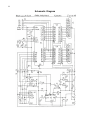
NWRD Nixie Watch
User Manual
Copyright (C) 2005 Cathode Corner. All rights reserved.
2
Table of Contents
Introduction ..................................................................................................................................................3
Warranty.......................................................................................................................................................4
Operating Instructions ..................................................................................................................................5
Maintenance..................................................................................................................................................7
How it Works...............................................................................................................................................9
Programming the Watch.............................................................................................................................12
Schematic Diagram.....................................................................................................................................14
3
Introduction
The Cathode Corner Nixie Watch is just about the most unusual yet practical timepiece you can wear on
your wrist. It is a two-digit nixie tube wristwatch designed for everyday use. It’s guaranteed to get
attention. People will ask you, “What is that? Is it a watch? Show me how it works.”
The Nixie Watch is water-resistant and rugged. The long-life, readily available battery may be changed
without tools. The watch requires no button pushing to operate – it shows the hours, minutes and seconds
in sequence at the flick of the wrist. It provides a bit of theater with every reading.
The large round crystal shows off the workings of the watch: the tubes, battery, high-voltage power supply
and setting controls are all visible.
The watch features 12 or 24-hour time display mode, user-settable tilt angle, and easy time setting
operation. The timekeeping rate is adjustable and the watch comes pre-adjusted to within a few seconds a
week.
The two Nixie tubes are the widely available B-5870 type and are socketed for easy replacement in case of
damage. (They have been known to develop short circuits between adjacent cathode plates as a result of
mechanical shock.) These tubes have 0.6” (15mm) tall digits for easy reading in adverse conditions.
Opening the case by unscrewing the ribbed cover reveals the time setting buttons, the battery and the tubes.
For the hardcore code hacker, a programming adapter allows the open-source PIC software running the
watch to be changed at will.
The case is made of strong, lightweight aircraft aluminum, hard anodized for lasting beauty. The rear of the
case is gently contoured for comfort in all-day use. An O-ring seal keeps out water, dust and dirt. The strap
is a standard 20mm size, so a replacement strap is available at any fine jeweler.
Specifications
Size: 2.2” (55mm) diameter by 0.79” (20mm) thick
Weight: 2 oz. (60g) exclusive of strap
Crystal window: 1-3/4” (45mm) diameter x 1.8mm thick mineral glass
Strap width: 20mm between lugs
Battery life: Approximately 4 months at 50 viewings per day, not using seconds display
Replaceable Parts
Battery: CR2 lithium (non-rechargeable), 3 Volt, 750mA-hour
O-Ring: Buna-N rubber, AS568 size 032, 1.875” ID x .070” cross section
Screws: Two 0-80 x 3/32” stainless steel socket head cap screws
Nixie tubes: Two B-5870 or equivalent, 0.6” (16mm) tall digit side-view nixie tubes
Integrated Circuits
Processor: PIC16F872A, 8192 instructions per second
Cathode drivers: 2x TD62083AFN
Power supply controller: LT1308A or B
Tilt sensor: ADXL311
4
Warranty
Thank you for your purchase.
The Nixie Watch is guaranteed for a period of one year after date of purchase to be free of defects in
materials and workmanship. In case of malfunction, the watch will be repaired or replaced at the discretion
of Cathode Corner. The customer must send the watch prepaid to the address given below on this page (or
as listed on the website mentioned below). This warranty does not cover the cost of shipping the watch to
Cathode Corner for evaluation. It does cover the return postage to the customer.
The software programmed into the microprocessor in the watch is licensed under the General Public
License and carries NO WARRANTY WHATSOEVER, including merchantability and fitness for a
particular purpose. See the source code files on the www.cathodecorner.com website for more information.
Contacting Cathode Corner
Cathode Corner wants to have only satisfied customers. If you are having trouble with your watch or you
just want to talk with us about fun things, you may contact Cathode Corner in any of the following ways.
Visit Cathode Corner on the Web at www.cathodecorner.com
Phone: 520-795-7228
Email: [email protected]
Mailing address:
Cathode Corner
2602 E Helen
Tucson AZ 85716
USA
5
Operating Instructions
Installing the Battery
The watch is shipped with a new battery in its original packaging. To install the battery, you must open the
watch case. This is done by holding the back of the case by the strap lugs in one hand while turning the
front cover counter-clockwise with the other hand.
The battery fits into the open space with the spring holder. The spring is in contact with the negative (-)
terminal of the battery, while the positive (+) terminal rests against the flat round contact. To insert the
battery, push its negative end against the spring terminal until the positive end slips into position. The
spring is rather strong to keep the battery from losing contact when the watch is bumped.
Setting the time
You may set the time on the nixie watch by pushing the two buttons below the display in the proper
sequence. The button on the left side is the Set button. It selects the time-setting mode. The button on the
right is the Adv button. It advances that portion of the time that is selected for setting. If you push the Adv
button first, the watch will enter the diagnostic tilt display mode.
The Set button cycles through a sequence as follows:
Normal display mode
12/24 hour select
Hour setting
Tens of minutes setting
Units of minutes setting
Seconds reset
Tilt angle
Normal display mode
Go ahead and press the Set button repeatedly to see the different setting modes. You will see the following
in sequence: 12 01 00 <incrementing number> 45
When you have finished the cycle, the display will be blank again.
To begin setting the time, press the Set button once. The display will show 12. Pressing the Adv button
causes this number to alternate between 12 and 24. When 24 is selected, the watch is in 24 hour display
mode and the hours will range from 00 to 23. When 12 is selected (the default), then the watch is in 12
hour mode and the hours will range from 01 to 12.
Press Set to enter hour setting mode. The watch displays a blinking 01. This is the hours. To increment the
hours, press the Adv button repeatedly until the proper hour is displayed.
Press Set to set the tens of minutes. The watch displays the current minutes with the left digit blinking.
Press Adv repeatedly to set the left digit of the minutes properly.
Press Set to set the units of minutes. The watch displays the current minutes with the right digit blinking.
Press Adv repeatedly to set the right digit of the minutes properly. It’s a good idea to set it one minute
ahead so that the seconds reset that follows will leave the watch set to the correct minute.
Press Set to enter the seconds reset mode. If you like, you may reset the seconds to 00 when your reference
clock reaches the top of the minute. However, the setting mode automatically turns itself off after 20
seconds have elapsed without any button pushes, so you may want to go back and reset the seconds when
the reference clock is at about :50 seconds.
Press Set to enter the tilt angle setting mode. The watch will display 45, which is a hint of the angle (in
degrees) to hold the watch at when setting the tilt angle. Hold the watch at a comfortable viewing angle with
6
the tubes facing up and toward your face, and press the Adv button. The display will blink once as the tilt
sensor is read and its angle stored for reference.
Press Set again to exit time setting mode. The display will be blank. Hold the watch steady at the tilt angle
you set it to, and the display should flash the hours and minutes. If you have difficulty getting it to display
the time, try setting the tilt angle again at a slightly different angle.
Using the watch
The nixie watch is simple to use. Once it is set, it will activate the display when tilted to the desired viewing
angle. The hours are displayed first, then the minutes, then finally an incrementing seconds display if held
at the viewing angle.
It may take some practice to get the watch to display the time every time you tilt it to viewing angle. In the
current version of the software, the tilt angle sensitivity is variable depending on exactly what angle the
watch is set to. So if it’s not sensitive enough, try setting the tilt angle again. That will usually clear up the
problem.
After a while, your arm will seek the correct angle automatically.
The seconds display is designed to indicate the passing seconds while minimizing the power used. The
seconds will only show up as long as the watch is held at the proper viewing angle. Also, the duty cycle of
the display diminishes to zero over a period of twenty seconds. You will notice that the time that each
number is displayed grows gradually shorter, until the display is flashing each passing second very briefly.
In spite of this, it is easy to read the displayed number since you know what it will be.
Water resistance
The nixie watch is designed to be water resistant, but it is not sealed against pressure. It should withstand
rainfall, splashes and other everyday liquid events. However, the seal may not be sufficient to protect the
watch against submersion in water. If it should be submerged, remove it from water right away, dry off the
outside of the case, unscrew the cover and check for water ingress. If the insides have gotten wet, first
remove the battery, then shake out any loose water and dry the watch by placing it in a warm, dry area with
the cover off.
If the inside of the watch has been soaked in water, it may be a good idea to remove the module with the
supplied .050” hex driver to allow drying of the module and the inside of the case.
7
Maintenance
Changing the battery
The battery is expected to last from two to six months, depending on the frequency of use. Experience has
shown it to last about three to four months in regular long-term use. If the watch is never activated, the
battery should last about a year.
Should the display grow fuzzy or blink off in use, the battery is likely to be dead. Replace it as follows:
Unscrew the cover.
Remove the old battery and discard it lovingly.
Install the new CR2 lithium battery with the flat end towards the spring and the bumped end towards the
flat round contact. IT will appear to be upside-down.
You may need to reset the time since the watch only remembers its settings for a few seconds when the
battery is removed.
Reinstall and screw on the cover.
Water resistance
The nixie watch is designed to be water resistant, but it is not sealed against pressure. It should withstand
rainfall, splashes and other everyday liquid events. However, the seal is not sufficient to protect the watch
against submersion in water. If it should be submerged, remove it from water right away, unscrew the cover
and check for water ingress. If the insides have gotten wet, first remove the battery, then shake out any
loose water and dry the watch by placing it in a warm, dry area with the cover off.
If the inside of the watch has been soaked in water, it may be a good idea to remove the module using the
supplied 0.050” (1.25mm) hex driver to allow drying of the module and the inside of the case.
Removing the module
Some maintenance operations require you to remove the watch module from the case. A .050” hex driver
has been provided for this purpose. The module is held in place in the case by two screws, one above the
battery negative contact spring and the other between the bases of the two nixie tubes. The screws are rather
small, so it is best to work on the watch over a white cloth so that the screws do not get lost.
First, unscrew the cover.
Remove the battery.
Unscrew the screws one at a time using the hex key.
Lift the module out by the battery spring.
Dump the screws onto the cloth and put them in a safe place.
Replacing the nixie tubes
The nixie tubes are somewhat delicate and may develop shorts between two adjacent cathodes after a bump.
The only known cure is to replace the bad tube. Replacement tubes are available from Cathode Corner.
Since several types of tube exist, you will need to identify the tube type if getting only a single replacement
tube. Contact Cathode corner for more information.
The procedure described below is rather tricky. You may elect to have Cathode Corner replace the tube(s)
for you. If so, send the watch and appropriate payment to the address on page 3. You may also elect to have
8
a watch repair shop do the work, but they are not likely to have any more experience at it than you do. They
may have better tools, however, and they might be amused to see such an unusual watch.
To replace a tube, it is necessary to remove the module from the watch case as described above. The old
tube may be removed by simply pulling its nipple end up to clear the transformer, then pulling it out of the
socket. The tube is held in place with a small pad of double-sticky foam tape. This tape is likely to tear, so
replacement foam pads are provided with every tube order.
Peel off the old foam pad. Remove the covering from one side of a new foam pad and press it into place
where the old one was, in about the center of the space left by the tube. Leave the top cover sheet on the
foam pad intact. It will be removed after the tube is plugged into the socket.
Installing the new tube can be tricky. It is done most easily under a microscope, but any magnifying lens is
helpful. It is best to use a self-supported magnifier since both hands are needed to install the tube. A pair of
fine point tweezers or a fine-tipped prod tool is also very helpful to coax the tube pins into the socket.
The tube pins are made of thin wire and are flexible. This is good in that it’s easy to align them, but bad
because they need to be aligned. The tube comes with a plastic spacer that keeps the pins aligned
moderately well.
First, the tube pins should be prepared. Inspect them and bend the pins so that they point straight out from
the plastic spacer. Check that the rows of pins are straight. Then pull the spacer off the tube and set it aside.
The two pairs of pins nearest the back of the tube often have trouble entering the socket unless they are
bent just a little bit towards the other pins. So do that. A distance of .020” (0.5 mm) is sufficient.
Now hold the module in one hand while holding the tube in the other hand, and guide the tube into place.
The front pins will engage first, followed by the rear pins. The tube may just slide into place, or one or
more pins may get hung up on the socket. This happens because the pin ends are cut square and the
sockets have an insert with a little shelf for the pin to get stuck on.
This is where the tweezers or prod come into play. Push gently on the stuck pin in the proper direction to
center it in the socket, and it should pop into place. If that doesn’t work, then try removing the tube and
bending the affected pin the proper way to allow it to fit on the next try. It may take a few tries, but it will
eventually go in. Check to be sure that all eleven pins went into their sockets.
After the tube is installed, the foam pad needs to be made sticky on top and the tube stuck down. Do this by
using the tweezers or prod to remove the top covering from the pad, then making sure the tube is aligned
with the other tube and pressing it down into place on the foam pad.
After the tube(s) have been replaced, the module may be reinstalled in the case. Drop the module into the
case and align the two screw holes in the module with the holes in the case. Place a screw on the hex driver
tip and guide it into position in one of the screw holes. Screw it down nearly all the way. Install the other
screw using the same method, then tighten both of them finger-tight with the hex driver.
Install the battery and set the time. Check that the tubes are displaying properly. Replace the cover, and you
are ready to go.
9
How it Works
History
The Nixie Watch uses modern electronics to light up the vintage nixie tubes. The tubes themselves are the
GR-116 or B-5870 type, which was designed originally for use in calculators in about 1970. By the time
1973 rolled around, the LED display had taken over the calculator market. Thousands of unsold nixie tubes
were left moldering in warehouses, since no one wanted an old-fashioned nixie tube calculator any more.
Fast-forward 30 years. With the proliferation of LCD displays on everything electronic, the quaint 3D
display of the nixie tube has a certain appeal. The fully-formed numbers are more aesthetically pleasing
than the crude 7 segment displays we have become accustomed to. Driver electronics are now tiny.
Nixie tubes
The nixie tube works like a neon lamp. It consists of an evacuated glass tube to which a small amount of
neon gas has been added. The tube contains ten metal cathodes shaped like numbers 0-9, surrounded by a
metal screen anode. When a positive voltage of about 180 Volts is applied to the anode mesh relative to a
cathode element, the neon gas surrounding the cathode sees a strong electric field. This electric field causes
the electrons surrounding the neon atoms to change energy level, thereby emitting orange photons. The
electric field strength with 180V is only high enough to cause the glow to occur very near to the cathode
element. The excited condition of the gas that causes it to glow is called plasma.
Once the plasma has started, the excited electrons will bump other electrons out of their energy levels,
causing the glow to be sustainable at a lower voltage of about 140V. The current that flows through the tube
is on the order of one to two milliampere s. A current of less than one milliampere will not light the
cathode completely, while more than two milliamperes will wear out the tube prematurely.
The cathodes may be switched by less than 140V swing. Since a cathode will not light if the anode-cathode
voltage is less than about 120V, it is only necessary to raise the unlit cathodes to a voltage 50V above
ground to cause them to stay dark if another cathode is lit in the same tube. This fact is important as it
allows the use of some very small cathode driver chips, which reduces the size of the finished watch.
The watch is run in multiplexed mode, which means that only one tube is lit up at a time. This can be seen
by shaking the watch as it displays the time. The tubes display a stroboscopic effect as they turn on and off
rapidly. The reason that multiplexed mode was chosen is that it reduces the power requirements since only
one tube is active at a time, and it allows the current regulation scheme described below to work.
Display Drivers
The tubes are driven by the two chips U3 and U4, which are Toshiba TD62083AFN octal Darlington driver
chips. Each driver chip has eight open-collector 50 Volt transistor driver circuits, designed to be driven
from logic level signals of about 3V.
Pin 10 of each chip is connected to the cathodes of protection diodes wired to each output pin. The purpose
of these diodes is to clamp the output voltage to a safe maximum voltage to prevent damage to the
transistors. This clamping voltage is derived by a 47V Zener diode from the high voltage tripler’s first
stage.
Pin 9 of each chip is connected to the emitters of all the driver transistors. It is used to monitor the current
drawn by the tube for regulation of the display brightness as described below.
Microcontroller
The nixie watch employs a PIC16LF872 microcontroller U2 to read the tilt sensor, control the power
supply and select which digits to light up. The microcontroller also keeps track of the time of day. The
processor runs at a very slow speed to save power. It executes only 8192 instructions per second, so the
10
software that controls the watch as been carefully crafted to operate as efficiently as possible. The power
used by the microcontroller is about 20 microamperes.
Oscillator
The microcontroller’s oscillator is connected to a standard 32768 Hz quartz watch crystal. This frequency
is chosen because it can be divided by two fifteen times (21 5) to produce exactly one pulse per second. The
oscillator circuit has a variable capacitor to allow adjustment of the operating frequency to within a few
parts per million (PPM), which corresponds to a few seconds a week timekeeping error. The oscillator is
adjusted at the factory to +/-1 PPM at about 25 degrees C.
Any crystal oscillator is subject to both temperature and aging variations. The AT strip crystal used in this
and nearly every watch has a negative slope parabolic frequency vs temperature curve, with the zero slope
point at 25C. Thus the watch will run slower if very hot or very cold.
Tilt Sensor
A dual-axis accelerometer U5 is used to detect when the watch is held at the correct angle for viewing. This
device, the ADXL311JE made by Analog Devices, contains a micro-machined floating plate held up on tiny
silicon springs. The plate is moved by the force of gravity, just as any plate suspended on springs will
stretch the springs above it. Sets of interlocking fingers on each side of the plate form capacitors that are
used in oscillators. The frequency of oscillation is a function of the capacitance, which is a function of the
spacing between the fingers. The spacing is a function of the force being applied to the plate by gravity.
The accelerometer converts the frequency of oscillation of each of the X- and Y-axis oscillators into voltage,
which is read by the microcontroller using an on-chip analog to digital converter (ADC). Thus, the
microcontroller is able to learn at what angle the watch is currently held relative to the earth. The scale factor
is such that on the scale of 0 to 255 of the ADC, each axis of the accelerometer puts out a value of
approximately 128 for 0g, 140 for +1g, and 116 for –1g.
The accelerometer is mounted on the small PC board to the left of the display tubes. The reason is that it
has to be mounted at such an angle that it can sense the rotation of the watch as it is brought into reading
position from the rest position. The specific quadrant desired is that with the tubes facing up, but with the
nipple end above the pin end of the tubes. Since the accelerometer provides indication of polarity as well as
magnitude of gravity’s pull, it is able to indicate whether the tubes are nipple-up or nipple-down and faceup or face-down. The relative magnitude of the X and Y axes indicates the angle within the quadrant, in the
sense that X is the cosine of the angle and Y is the sine of the angle.
The accelerometer chip uses about 1/3 milliampere of current , so it would drain the 800 mAH battery in
three weeks if allowed to be powered on continuously. Therefore, the chip is only powered up for a few
milliseconds at a time, several times a second, to measure the tilt angle. This results in an average current
draw of about ten microamperes.
Power Supply
The nixie display tubes require about 180V to light up (strike) the neon gas and about 140V to sustain the
orange plasma glow. This high voltage is provided by a small DC-DC converter chip, U1. The converter
uses a 1:12 step-up transformer driven by a 600 kHz switching controller to make about 60VAC, which is
boosted to 180VDC by a voltage tripler circuit made of three diodes and three capacitors.
It is a boost-mode switching converter. This means that the inductor comprising the primary of the
transformer is given a pulse of energy, which causes it to make a high-voltage inductive ‘kick’ when the
pulse ends. This ‘kick’ is multiplied by the winding ratio of the primary to secondary to produce the 60V
AC square wave that is applied to the voltage tripler.
The DC-DC converter controller chip, an LT1308A, monitors the high voltage being produced via its
feedback pin FB (pin 2), which is fed from the high voltage output by a resistive divider network. A voltage
11
of 1.21V is expected on this pin. The controller increases the duty cycle of the square wave if more voltage
is needed, or reduces it if the output voltage is too high. Increasing the duty cycle has the effect of
increasing the amount of energy transferred into the transformer.
Voltage regulation
The resistive divider used to monitor the output voltage is rather sophisticated. It consists of two resistors in
series, R1 and R4, that monitor the voltage being applied to the tube anodes. The bottom end of the divider
has a low-valued resistor R8 that is connected in series with the common emitter connection of the nixie
tube cathode driver chips U3 and U4. This allows the voltage divider chain to measure the current drawn by
the lit cathode(s). Between R4 and R8 is a resistor, R6, which together with R8 form the bottom half of the
divider.
The reason for the two resistors R1 and R4 is because the little tiny resistors used are only rated for
100VDC, so the voltage-dropping work is split into two. The resistor R6 does most of the work of
producing the 1.21V feedback voltage to the chip, while R8 produces additional 0.3V feedback voltage
when two milliamperes of current is drawn by the lit tube. The voltage across R8 causes the feedback
voltage to increase, so the chip reduces the output voltage to compensate. This results in reduced output
voltage when the tube is drawing current compared to when it has not yet struck. The resistor values are
chosen so that the supply puts out 180V with no load and 140V with a two milliampere load.
Current regulation
The tube current is interesting because the brightness is a function of current, not voltage. The voltage that
develops across the tubes is fairly constant, but the current directly controls the brightness. Most nixie
clocks use a resistor in series with each anode to control the current by selecting a supply voltage and a
resistance value sufficient to provide the correct current flowing through the resistor and therefore the tube.
The problem with this approach for a nixie watch is that the resistor wastes about 20% of the power
developed by the high voltage power supply.
The power supply runs at about 50% efficiency (total including tripler), resulting in a battery current
consumption of about 200 milliamperes when both tubes are lit up. This is not ideal, but it is difficult to
make a high voltage supply this small with higher efficiency using off-the-shelf parts.
Blanking
Yet another connection to the resistive voltage divider provides a means of reducing the tube voltage to
about 120V so that the display may be blanked and relit quickly for multiplexing and blinking the digits.
This is R7, which is also connected to the tilt sensor power pin. (This has no relation to the tilt function; it
was the only pin available on the microcontroller chip.) When this pin is at 0 volts, R7 pulls the feedback
pin down slightly. When it is at 3V, it pulls the feedback pin up slightly. The resistor value is chosen to
produce 180V when low and 120V when high.
Software
The software that controls the nixie watch is contained in the source code file nwrd.asm (available on the
Cathode Corner website http://www.cathodecorner.com/nixiewatch/ or by writing to Cathode Corner). It is
written in PIC assembly language. Feel free to download it and peruse it at your leisure. The operation of
the software is described in the comments contained in the source file.
12
Programming the Watch
This section applies only to people who are familiar with microcontrollers and the programming thereof.
The nixie watch is controlled by a Microchip PIC controller. This is a tiny single-chip computer that
executes a complex program to keep track of time, detect the tilting of the watch, and display the hours,
minutes and seconds in sequence.
The computer can be reprogrammed to add features or improve the software. This activity requires special
programming hardware that is not owned by the average person; therefore, it is of interest mainly to people
with experience programming microcontrollers.
The software is contained in the source code file nwrd.asm (available on the Cathode Corner website or by
writing to Cathode Corner). It is written in PIC assembly language.
Feel free to inspect the code, change it around, reprogram the chip, and send your changes to Cathode
Corner for inclusion in future watches. We would appreciate it if you can make improvements to the code.
The things that could use some improvement:
The tilt display mode would look better with decimal conversion.
The setting mode may be improved upon, especially to add a quick time-zone change function.
The tilt angle sensing code could use all 10 bits of the ADC for more consistent results.
The included NWRD programming adapter allows a standard Microchip ICD2 or similar in-circuit
programmer with a 6-pin Molex plug to be connected to the watch module. The watch module must be
removed from the watch case to attach the programming adapter. The programmer must be capable of
supplying 5V to the target chip, and be capable of programming a PIC16F872 in high-voltage mode.
The watch module is removed from the case by unscrewing the cover, removing the battery, then removing
the two socket head screws with a .050” (1.25mm) hex key. One screw is located between the two tubes at
the socket end of the tubes, and the other is located above the battery spring terminal. The module may then
be lifted out of the case.
The programming connector J1 is located below the base of the two tubes. It is a 2 x 3 pin 2mm socket
array. The programming adapter plugs into this socket with six very delicate little gold pins. There is no
shroud on the connectors, so care is required to get the plug in the right way and make sure all pins go into
their respective sockets. The Molex connector on the adapter should be attached to the programmer first,
then the adapter plugged into the watch module.
The orientation is with the Molex connector closest to the front face of the watch module. The adapter
should not stick out behind the module; if it does, it’s backwards or off by one row of pins. Double check
that all pins are engaged properly, as you could damage the watch if the connector is in the wrong place.
It’s rather difficult to replace a burned-out PIC processor.
Follow the programming instructions for your PIC programmer. You will need to supply target power to
the nixie watch board over the Vcc pin on the programming connector.
Set the configuration bits in the programmer configuration menu as follows:
No brownout protection
No watchdog
LP oscillator (low power)
No low-voltage programming
EEPROM: Not used by the standard code; protect is don’t care
13
Code protect: Not unless you want to hide the code from yourself
Some programmers require you to plug in the various signal and power connectors in a specific sequence.
For example, the Olimex ICD2 with MPLAB 6.50 requires the following sequence:
Attach target board to programmer
Connect DC power adapter to programmer
Connect USB cable to programmer
Start the MPLAB program
Tell MPLAB to connect to device
Tell MPLAB to program the part
Quit MPLAB
Disconnect USB cable
Disconnect DC power adapter
Disconnect target board
Furthermore, the Windows USB driver will time out after some minutes of inactivity, so don’t start
MPLAB then go eat dinner and expect it to work when you return. The program hangs, and the only way to
end the hang is to unplug the USB cable from the programmer.
14
Schematic Diagram