1
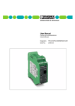
MCR Threshold Value Switch, Programmable - MCR-PSP
Output
Relay level
Switching output 1 (K 1)
Switching point 1, lower limit (SPL)
Switching point 1, upper limit (SPH)
2 x PDT contacts / 2 switching points each
low/high (settable)
1 x Um (AgNiO 0.15 + HTV hard gold-plated) 250 V AC, 2 A
min. input value ... max. input value – double switching tolerance
min. input value + double switching tolerance ... max. input value
Switching output 2 (K 2 )
Switching point 2, lower limit (SPL)
Switching point 2, upper limit (SPH)
1 x Um (AgNiO 0.15 + HTV hard gold-plated) 250 V AC, 2 A
min. input value ... max. input value- double switching tolerance
min. input value + double switching tolerance ... max. input value
Cycles
Setting accuracy
Tolerance/Hysteresis around the switching point
30 x 106
0.1 °C/0.1 °F/0.1 Ω/0.01 V/0.01 mA
Depending on the type of sensor set
(see 2.5. switching tolerance of different inputs, page 11)
0.0 ... 1.0 secs, can be set in 0.1 sec. steps
1.0 ... 2.0 secs, can be set in 0.2 sec. steps
Delay time high/low of the relay
2.2. General Data
Supply voltage
Current consumption
Temperature coefficient
Test voltage: auxiliary power supply/input
Protection circuit
Ambient temperature range
Display resolution
Offset error (Zero)
Gain error (Span)
Linearity error
Total error
Type of connection:
• Input
• Output and supply
Installed position / mounting
Standards and regulations
20 ... 30 V DC
< 60 mA
≤ 0.01 %/K
1 kV, 50 Hz, 1 min.
transient protection, polarity protection
-20 °C to + 65 °C
0.1 °C/ 0.01 V/0.01 mA/0.1 Ω
typ. < 0.05% F.S.
typ. < 0.05% F.S.
typ. < 0.05K (only for RTD and THC)
typ. < 0.1% F.S.
screw terminal block
pluggable screw terminal block
any
IEC 664/IEC 664 A/DIN VDE 0110-1:1989-01l
Type of housing
ABS,
see Online catalog
color: green
Torque value of terminal screws, see Online catalog.
Marking systems and mounting material, see Online catalog.
The rated cross section (see Online catalog) refers to untreated
conductors without ferrules.
2.3. (EMC) electromagnetic compatibility
c
Complies with EMC guideline 89/336/EEC and low voltage directive 73/23/EEC
Immunity to interference in acc. with EN 50082-2
• Electrostatic discharge
(ESD)
EN 61000-4-2
Criterion B
8 kV discharge in air
• Electromagnetic HF field:
Amplitude modulation
Pulse modulation
EN 61000-4-3
Criterion A
10 V/m
10 V/m
• Fast transients
(Burst)
EN 61000-4-4
Criterion B
I/O/S: 2 kV/5 kHz 1)
• Surge voltage capacities
(Surge)
EN 61000-4-5
Criterion B
I/O: 2 kV/42 Ω 1)
• Conducted disturbance
EN 61000-4-6
Criterion A
I/O/S: 10 V 1)
• Noise emission in acc. with EN50081-2
EN 55011
Class A
EN 61000 corresponds to IEC 1000
EN 55011 corresponds to CISPR11
1) I = Input / O = Output / S = Supply
Criterion A: Normal operating behavior within the defined limits.
Criterion B: Temporary impairment of operational behavior that the device corrects itself.
Class A: Area of application: industry, without special installation measures.
PHOENIX CONTACT page 3 of 15