1
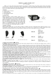
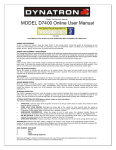
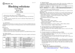
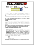
User Manual
Installations
Required Tools as below
Electric or battery operated Drill
A Hammer
One Drill bit
A pair of pliers
A Carpenter Chisel
A pair of scissors
Philips & flat head screw drivers
A. Installation of the outside unit.
1. Put the rubber gasket to the back of the outdoor unit.
2. Make sure the UP marks are on the two sides of the spindle,
instead of top side.
3. Insert spindle through the 21 mm hole.
4. Insert the connector and wire through the bigger upper hole
( Dia: 17 mm).
5. Insert the two upper fixing posts through the small upper holes
on the door and the bottom post through the bottom hole.
B. Installation of the inside unit.
1. Put the rubber gasket to the back of the inside unit.
2. Connect the 2 sets of wires and insert all the wires into
the wire hole on the door.
3. Make sure the arrow mark on the spindle tube of the
inside unit on the top position.
4. Insert the spindle through the spindle tube of the indoor
unit.
5. Gently finish joining the outdoor and indoor units
together, ensuring all fixing posts are aligned properly.
Make sure the cables are not jammed by the door.
6. Turn the handle to test the operation of the latches.
7. Remove the cover of the battery house of the inside
unit. Fasten the two middle-length screws into the
screw holes inside the battery house and through the
two upper fixing posts.
8. Fasten the longest screw into the screw hole below the
inside handle and through the bottom fixing post.
9. Insert 3 high-quality AA batteries - this will enable you to
program and test the lock.
10. Put the battery cover on and fasten the screw.
BioAxxis®
® PCL-1 PIN Code lock
User Manual
C. Final inspection/adjustment prior to setup and use.
①
②
.
③
&
2
(
,
!
!
!
!
'
/
"
#
/
,
,
!
(
$
%
'
&
/
'
(
,
/
"
&
(
*
'
(
)
1
)
"
*
+
/
(
&
1
'
0
&
-
0
.
!
!
"
)
"
(
"
"
!
/
,
!
&
(
#
+
/
3
'
,
4
&
)
1
,
!
1
,
!
&
(
)
"
#
-
-
,
&
"
/
&
"
'
/
!
1
'
3
,
)
$
5
6
9
2
,
/
,
3
!
:
3
7
"
;
1
!
8
,
<
,
=
8
,
>
4
?
8
,
@
A
,
!
(
)
,
,
-
B
OPERATIONS
ADDING THE PIN CODES:
There can be TEN sets individual PIN codes set from the outside unit. The Set number ranges from 0 to 9. The
original factory-set system PIN Code is
. The PIN code can be 1 digit up to 10 digits.
?
▲
?
@
A.
B
B
C
D
9
E
F
?
G
H
;
<
=
:
@
A
:
<
=
:
B
:
B
ADD the Master 1 PIN code:Enter * + 0 + 123 + * (Green LED blinks) + New PIN code + * (Green
LED blinks) + New PIN code again + *
When the green LED blinks and one long beep is heard, the operation succeeds; if the Red LED blinks, the
operation fails.
B.
ADD the Master 2 PIN code:Enter * + 0 + the 0 set PIN code + * (Green LED blinks) + New PIN
code + * (Green LED blinks) + New PIN code again + *
When the green LED blinks and one long beep is heard, the operation succeeds; if the Red LED blinks, the
operation fails.
C.
ADD the User PIN code:Enter * + 2~9 + one of the master PIN codes + * (Green LED blinks) +
New PIN code + * (Green LED blinks) + New PIN code again + *
When the green LED blinks and one long beep is heard, the operation succeeds; if the Red LED blinks, the
operation fails.
DELETING THE PIN CODES:
Enter * + the set number of the PIN code which should be deleted + one of the master PIN codes + #.
When the Green LED blinks, the deletion operation succeeds; if the Red LED blinks, the operation fails. I.E. If we
want to delete the 2nd set PIN code, enter *+ 2 + one of the master PIN codes + #.
BioAxxis®
® PCL-1 PIN Code lock
User Manual
▲
9
<
=
:
:
B
9
:
:
B
TEMPORARY UNLOCKING MODE & AUTOMATIC LOCKING MODE (TUM)
▲
9
:
;
:
:
B
Enter # + 1 + one of the master PIN codes + # (with the Green LED blinking) + 1 to trigger the Temporary
Unlocking Mode (TUM). When the Green LED blinks again and one long beep is heard, the lock gets into
Temporary Unlocking Mode (TUM), and user can turn down the handle to unlock without the need to enter any
PIN code.
Enter # + 1 + one of the master PIN codes + # (with the Green LED blinking) + 0 to get the lock back to
Automatic Locking Mode. When the Green LED blinks again and one long beep is heard, the lock gets back into
Automatic Locking Mode, and user cannot unlock from outside before one correct PIN code is entered.
▲
Temporary Unlocking Mode might possibly get your house or room into insecure situation. Unless
you’re sure it’s 100% necessary and safe, otherwise it’s strongly recommended not to apply this functionality.
ANTI MALICIOUS OPERATION SETUP
Enter # + 2 + one of the master PIN codes + # (with the Green LED blinking) + 1 to trigger Anti Malicious
Operation functionality. When the Green LED blinks again and a long beep is heard, this functionality is
triggered.
Enter # + 2 + one of the master PIN codes + # (with the Green LED blinking) + 0 to cancel this functionality.
When the Green LED blinks, this functionality ceases to work.
▲
When this functionality is applied, any wrong PIN code access attempts on five consecutive occasions
will immobilize the lock for 5 minutes. During this period, any button on the outside unit will cease to function.
Unlocking from the Outside Unit
The power button on the outside unit is used to trigger the night-view light beneath the PIN code keypad. This
night-view light will last 3 seconds with no operation following, but will not turn off until any operation on the
keypad is accomplished.
1) Fully lift up the outside sliding cover.
2) Directly enter one existing outside PIN code + # (or + *, or + the PWR button).
When you hear the motor moving, turn down the handle to unlock.
When the power is lower than 3.3V, the lock will send out low-power alert. You’ll hear 8 beeps
BioAxxis®
® PCL-1 PIN Code lock
User Manual
and see the red LED blink.
Open from inside (exit)
Turn down the inside handle to open.
BioAxxis®
® PCL-1 PIN Code lock