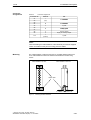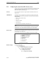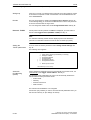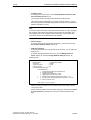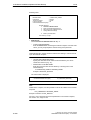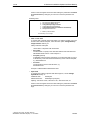
1
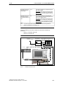
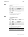
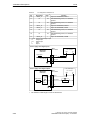
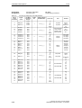
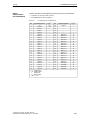
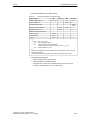
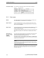
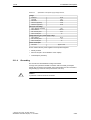
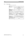
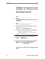
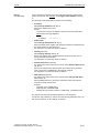
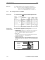
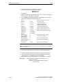
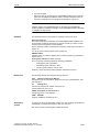
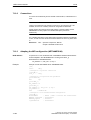
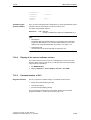
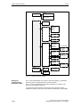
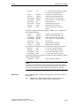
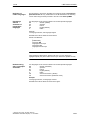
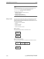
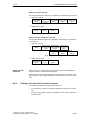
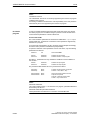
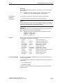
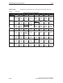
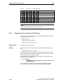
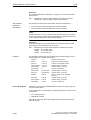
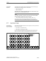
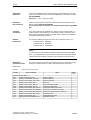
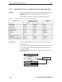
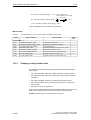
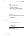
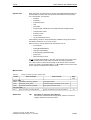
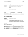
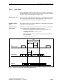
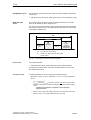
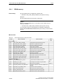
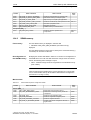
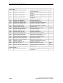
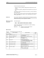
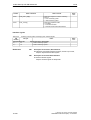
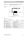
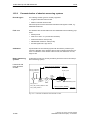
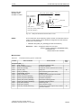
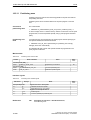
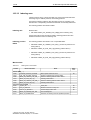
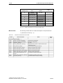
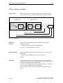
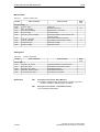
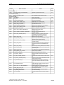
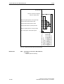
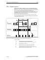
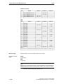
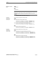
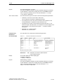
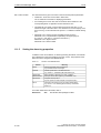
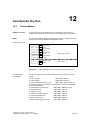
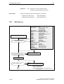
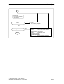
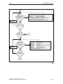
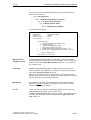
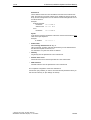
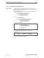
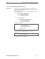
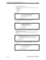
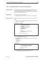
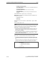
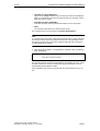
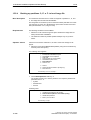
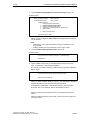
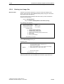
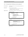
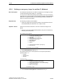
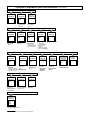
10 NC Start-Up with HMI Advanced 10.6 Digital and analog I/O devices 01.05 ET200 I/Os: IM 153 Slot Module I address O address 4 SM 322 DO16xDC24V/0.5A – 128...129 5 SM 322 DO32xDC24V/0.5A – 130...133 6 SM 321 DI16xDC24V/0.5A 128...129 – 7 SM 321 DI32xDC24V/0.5A 130...133 – I address O address Comment ADI4 Slot Module 4 Drive data 5 Drive data 6 Drive data 7 Drive data 8 Drive data 9 Drive data 10 Drive data 11 Drive data 12 Drive data 13 Drive data 14 Drive data 15 Drive data 16 Drive data 17 Drive data 18 Drive data 19 Drive data 20 Drive data 21 Drive data 22 Drive data 272...289 Comment 1. Axis 272...281 290...307 1. Axis 2. Axis 290...299 332...349 2. Axis 3. Axis 332...341 308...325 3. Axis 4. Axis 308...317 4. Axis 326...327 O word 326...327 I word Note: The structure of the PROFIBUS message frame is described in Section 8.8, Page 8-258f. Machine data Parameterization of the NC machine data is shown below: Number of inputs bytes ET200 3 input bytes ADI4 1 input byte Note Although only 4 input bytes are used, 5 must be declared. The 1st input byte is always assigned to the MCI board extension module, even if it does not exist: – 10-388 MD10350: FASTIO_DIG_NUM_INPUTS = 5 Siemens AG, 2005. All rights reserved SINUMERIK 840Di Manual (HBI) – 01.05 Edition