1
US006116767A
Ulllted States Patent [19]
[11] Patent Number:
Chaiken et al.
[45]
[54]
DISPLAYING AUDIO DISK TRACK NUMBER
IN PORTABLE COMPUTER SYSTEM
Date of Patent:
_
-
1/1997 Minoura ................................ .. 711/101
8/1997 Pearce
.. 713/200
5,745,772
4/1998
_
,
,
1u
5,898,600
Mark J. Schla?'er, Pinehurst, all of
.......
. . . ..
710/266
........................................ ..
4/1999 Isashi ............................... .. 364/705.01
FOREIGN PATENT DOCUMENTS
.
6X
-
Klein
iéarce 9t 91
glgfltlegl’épki?ligjg‘fog
T
*Sep. 12, 2000
5,592,640
5,657,445
[75] Inventors: Craig L. Chaiken, Tomball; Tim L.
~
6,116,767
_
-
0564092 A2
10/1993
European Pat. Off. .
0588084 A2
3/1994
European Pat. Off. .
[73] Asslgnee' E3151? geimputer Corporatlon’
9-101848
4/1997 Japan .............................. .. G06F 1/32
OTHER PUBLICATIONS
[*]
Notice:
This patent issued on a continued pros
ecution application ?led under 37 CFR
153((1), and is Subject to the twenty year
patent term provisions of 35 U.S.C.
Intel486TM SL Microprocessor Super Set Programmer’s
Reference Manual, Intel Corp., Nov. 1992, pp. 6—29 through
6—53~
154(21)(2)_
Enhanced IDE 95/96 Guide, Western Digital, Mar. 17, 1995,
pp. 17 through 42.
PentiumTM Processor User’s Manual vol. 3: Architecture
I
21
1
A 1' N ‘I 08 990 551
pp
9
/
[22] Filed:
and Programming Manual, Intel Corp., 1994, 20—1 through
,
2&9
Dec. 15, 1997
The Computer Desktop Encyclopedia, Alan Freedman,
1996, pp. 47, 226, 258, 479—480.
Related U.S. Application Data
[63]
Continuation-in-part of application No. 08/846,641, Apr. 30,
1997-
Primary Examiner—Thomas C. Lee
Assistant Examiner—Harold Kim
Attorney, Agent, or Firm—Akin, Gump, Strauss, Hauer &
[51]
Int. c1.7 ...................................................... .. G06F 1/16
Feld’ LLP
[52]
U.S. Cl. ......................... .. 364/7081; 710/15; 710/14;
[57]
ABSTRACT
364/710.05; 345/169
[58]
Field Of Search .................. .. 710/14, 15; 364/7081,
364/71005, 71001, 71007; 345/169; 361/679,
Acomputer System incorporating Capabilities for displaying
the audio disk track number When the computer system is
683, 685
playing an audio disk. The computer system determines if a
disk is present in the disk drive. If a disk is present, the
computer system determines if an audio disk is present in the
disk drive. If so, the computer system then monitors the disk
drive. When the audio disk is played by the disk drive, the
4,149,043
4/1979 Itoh et al. ............................... .. 369/10
Computer System displays the audio disk track number- The
4,497,021
4,852,073
1/1985 Fukuda et a1,
7/1989 Shinohara et al.
computer system then periodically polls the disk drive to
update the audio disk track number. The computer system
4,898,483
2/1990
479267373
5/1990 Takena_ka -
[56]
References Cited
U'S' PATENT DOCUMENTS
IiZuka . . . . . . . . . . . . . . . . . . .
__ 712/43
.. 369/32
. . . . ..
400/61
358/113
1:13;
goyagl ' ' ' ' '
5,377,358
,
,
12/1994
Nakamura
ussman .... ..
''''
707/507
5,404,546
4/1995
Stewart ...... ..
713/322
displays a battery gauge
status When the
audio disk track
number is not being displayed. The status display is visible
When the portable computer is in either an open or closed
5,477,129 12/1995 Myslinski ............................... .. 320/48
State‘
12 Claims, 7 Drawing Sheets
U.S. Patent
Sep. 12, 2000
6,116,767
Sheet 2 0f 7
200
f 202
CD
PRESENT
‘,7
QUICKPOST
/ 204
comm
/ 206
HKBC
RFABE
MINI CD-RDM _/208
DEVICE DRIVER
'
FI G- 2
TRACK
DISPLAY
NUMBER
GAUGE
312
FIG. 3
{61
' \\\
-
\ _ \\ 900/
\902
\904
310
U.S. Patent
Sep. 12,2000
Sheet 3 of7
6,116,767
414
FIG. 4
U.S. Patent
\mow
Sep. 12, 2000
Sheet 4 0f 7
6,116,767
6Em
wwwmow Ev8v
ES
mm
New
U.S. Patent
Sep. 12,2000
Sheet 5 of7
6,116,767
406
35
407
\
I
l \\
405 420 422 424 426
55!
l
1 Rll
9
FIG. 6
l
U.S. Patent
Sep. 12,2000
Sheet 6 of7
6,116,767
FIG. 7
KBC
DM_SW
DATA
SHIFT
/_ 806 REGISTERS
800
CLOCK
f 808
812
60 Hz CLOCK
814 L‘
802
I
818
BO Hz CLOCK
804
/
LCD CONNECTOR
15/57
FIG. 8
816
U.S. Patent
Sep. 12,2000
6,116,767
Sheet 7 0f 7
W
ENTER
AUDIO
CD MODE
I
r954
INITIALIZATION
+ r956
ENTER PDS
WAKE~UP
EVENT
'2
Y
r957
EXIT PDS
r964
ADDRESSES
EXTERNAL
SMI EVENT
I r962
CALLS
CD ROM
DRIVER
EXTERNAL
SMI
?
PDLL CD ROM
I
DISPLAY
TRACK NUMBER
I
f 970
SAVE AUDID
VDLUME LEVEL
FIG. 10
6,116,767
1
2
DISPLAYING AUDIO DISK TRACK NUMBER
IN PORTABLE COMPUTER SYSTEM
system is playing an audio disk. The computer system
determines if an audio disk is present in the disk drive. If an
audio disk is present, the computer system periodically polls
RELATED APPLICATION
the disk drive to determine if the audio disk is being played.
If an audio disk is being played, the computer system
displays the audio disk track number. The computer system
then periodically polls the disk drive to update the audio disk
track number. If an audio disk is not being played, the
This application is a continuation-in-part of US. patent
application Ser. No. 08/846,641, ?led on Apr. 30, 1997,
entitled “COMPUTER SYSTEM CAPABLE OF PLAYING
AUDIO CDS IN A CD-ROM DRIVE INDEPENDENT OF
AN OPERATING SYSTEM,” still pending to William E.
Jacobs, Dan V. ForlenZa, James L. Mondshine, Tim L.
Zhang, Greg B. Memo, Kevin R. Frost, and Lonnie J. Pope,
computer system displays the battery gauge (or other) infor
10
Which is hereby incorporated by reference.
BACKGROUND OF THE INVENTION
1. Field of the Invention
The present invention relates to displaying Compact Disk
(CD) status information on a computer, and more speci?
BRIEF DESCRIPTION OF THE DRAWINGS
15
cally to displaying the CD track being played in the
folloWing draWings, in Which:
2. Description of the Related Art
Operating a CD-ROM drive in a computer system has
liZing a CD-ROM drive application. The RAM-based
CD-ROM device driver of the CD-ROM drive application
alloWed for operation of the CD-ROM drive. The lengthy
duration of the booting process for an operating system and
the considerable user interaction required by a CD-ROM
drive application render playing an audio CD in the
20
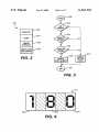
FIG. 2 is a diagram of the ?rmWare code in the audio CD
mode ROM of FIG. 1 for a keyboard controller embodiment
25
not involve a timely initialiZation process and substantial
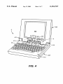
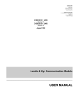
FIG. 4 is an isometric vieW of a portable computer case
30
in conventional computer systems, users have maintained a
containing the computer system of FIG. 1 in an open state
in accordance With the present invention;
separate audio CD player in place of the portable computer.
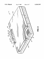
FIG. 5 is an isometric vieW of the portable computer case
of FIG. 4 in a closed state in accordance With the present
In addition, Where a user is aWay from his or her audio CD
invention;
35
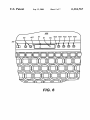
FIG. 6 is an enlarged plan vieW illustrating the portion of
the top surface of the bottom shell of the portable computer
case of FIG. 4 circled and having the numeral “6” desig
nating same;
40
computer system of FIG. 1;
an audio CD as quickly and easily as alloWed by a conven
tional audio CD player. Because of the initialiZation process
and user interaction required, portable computer users Would
often carry a separate audio CD player for music listening
even though the portable computer had music playing capa
bility. Also, since a CD-ROM drive application Was depen
of the present invention;
FIG. 3 is a How chart of a process according to the present
invention for displaying the audio disk track number on the
mini LCD of FIG. 1;
conventional audio CD player, undesirable. An audio CD
player, unlike a CD-ROM drive of a computer system, does
player, a conventional computer system due to its initialiZa
tion and user interaction requirements is unsuited to playing
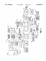
FIG. 1 is a schematic diagram of a portable computer
system shoWing an audio CD mode ROM, audio CD mode
sWitch, status indicator, and master volume control buttons
of the present invention;
CD-ROM drive of a computer system, as opposed to in a
user interaction. As such, despite the CD-ROM drive present
A better understanding of the present invention can be
obtained When the folloWing detailed description of the
preferred embodiment is considered in conjunction With the
CD-ROM drive of a notebook computer.
required booting an operating system and loading and uti
mation in the position the audio track number is displayed.
In the disclosed embodiment, the track information is visible
When the lid is in the closed position, alloWing the audio disk
track number display to be seen Without opening the lid.
FIG. 7 is a state diagram of the poWer control states of the
dent upon an operating system, it Was necessary to use a
display screen to visually indicate to the user When a
FIG. 8 is a schematic electrical circuit diagram of mini
status display screen control circuitry in accordance With the
CD-ROM drive application Was being operated. As such,
present invention;
portable computer users have been required to maintain the
portable computer case containing a portable computer in its
FIG. 9 is a diagram of the track indicator of FIG. 1 in
45
open state to determine the status of a CD-ROM drive
accordance With the present invention; and
FIG. 10 is a How chart of an alternative embodiment of the
application, including CD track information.
audio CD mode process in accordance With the present
invention.
Further, a conventional computer system has required a
user to access numerous locations, softWare and hardWare,
to obtain status and to adjust the volume and other settings
DETAILED DESCRIPTION OF THE
PREFERRED EMBODIMENT
50
of various audio sources such as a CD, Wave, and synthe
The folloWing disclosures are hereby incorporated by
siZer for music listening. These locations typically include a
mixer in a WindoWs®-based CD-ROM drive application for
reference:
controlling the volume of audio sources, a softWare master
volume control in a Windows@ task bar, and a hardWare 55
volume thumbWheel. As these volume control sources con
US. patent application Ser. No. 08/846,641, ?led on Apr.
30, 1997, entitled “COMPUTER SYSTEM CAPABLE
trolled volume independent of each other, it Was necessary
OF PLAYING AUDIO CDS IN A CD-ROM DRIVE
INDEPENDENT OF AN OPERATING SYSTEM,” to
for a user to sort through cumbersome CD-ROM drive
William E. Jacobs, Dan V. ForlenZa, James L.
softWare to adjust the volume of the appropriate audio
sources. In light of the softWare nature of certain volume
controls, it Was also necessary to maintain the portable
computer case in its open state With the display screen
visible to a user to alloW for certain volume adjustments
during music listening.
SUMMARY OF THE INVENTION
A computer system according to the invention that dis
plays the audio disk track number When the computer
60
Mondshine, Tim L. Zhang, Greg B. Memo, Kevin R.
Frost, and Lonnie J. Pope; and
US. patent application Ser. No. 08/879,911, ?led on Jun.
20, 1997, entitled “REAL-TIME BATTERY GAUGE
DISPLA ,” to Luke L. Mondshine, Dan V. ForlenZa,
Kevin R. Frost, and Greg B. Memo; both of Which are
assigned to the assignee of this invention.
Turning to FIG. 1, a schematic diagram of a portable
computer system S of the present invention is shoWn. Within
6,116,767
3
4
the portable computer S, a CPU 10 and a Level 2 (L2) cache
interrupt. An SMI is the softWare interrupt With the highest
priority, and is operating system independent. Generation of
12 are connected. The processor 10 is preferably a Pentium®
processor manufactured by Intel Corporation of Santa Clara,
an SMI also causes synchronous execution of an SMI
Calif. The processor 10 operates preferably With a standard
IBM-PC compatible operating system, such as Windows@
handler, Which is typically located in a protected memory
address space of the synchronous DRAM 16 or other system
95. available from MicroSoft Corporation of Redmond,
Wash. The L2 cache 12 provides additional caching capa
bilities to the processor’s on-chip cache to improve perfor
performing speci?c system management tasks, like reducing
memory. An SMI handler is an interrupt service routine for
mance.
The CPU 10 and the L2 cache 12 are connected to a
host/PCI bridge 14. Also connected to the host/PCI bridge
14 is a synchronous DRAM 16. The host/PCI bridge 14 is
10
further coupled to a PCI bus P that connects to a PCMCIA/
CardBus controller 18 and a video card 20 including a video
graphics controller and video memory. The video graphics
controller of card 20 provides control signals to the main
audio CD select signal DMSEL. In a “CD-ROM drive
15
liquid crystal display screen 406 (FIGS. 1 and 4). The
PCMCIA/CardBus controller 18 is also coupled to a set of
PCMCIA cards 22 for connecting a variety of peripherals to
the portable computer S.
controller” embodiment of the present invention, the
CD-ROM drive controller 102 is coupled to the audio CD
mode sWitch DMiSW 56 and receives the audio CD select
signal DMSEL. If the poWer sWitch PWRiSW 58 of the
computer system S is in an “on” state, the audio CD mode
sWitch DMiSW 56 is disabled such that toggling of audio
APCI/ISA bridge 24 is used to connect the PCI bus P and
an ISA bus I. Coupled to the PCI/ISA bridge 24 is an IDE
interface 26 Which connects to a CD-ROM drive 28 having
an IDE controller and to a hard disk drive 30. The IDE
interface 26 is preferably a busmaster and an IDE/ATA
interface having enhanced IDE features. The CD-ROM
drive 28 is preferably compliant With ATAPI (AT Attach
poWer to speci?c devices or providing security services.
SMI handler code thus may be Written by one of ordinary
skill in the art to perform a variety of system management
tasks.
In a “keyboard controller” embodiment of the present
invention, the keyboard controller 46 is further coupled to an
audio CD mode sWitch DMiSW 56 and also receives the
25
CD mode sWitch DMiSW 56 has no effect. The audio CD
mode sWitch DMiSW 56 is also disabled When the com
puter system S in a sleep mode. If the poWer sWitch
PWRiSW 58 of the computer system S is in an “off” state
such as a hibernate mode, the audio CD mode sWitch
DMiSW 56 is enabled.
includes tWo cascaded PICs for alloWing interrupt channels
When the audio CD mode sWitch DMiSW 56 is enabled,
the state of the sWitch 56 determines Whether the computer
system S is in an audio CD mode. The audio CD mode
sWitch DMiSW 56, When placed in an “on” state, serves to
place the computer system S of the present invention in an
audio CD mode. Audio CD mode is a secondary operational
mode Which enables the computer system S of the present
IRQ<|)—IRQ15.
invention to bypass traditional system BIOS and play audio
ment Packet Interface), the IDE standard for CD-ROM
drives, and includes a CD-ROM drive controller 102 that is
preferably embedded in the CD-ROM drive 28. Also, inte
grated in the PCI/ISA bridge 24 is a set of programmable
interrupt controllers (PICs) 15 for managing hardWare inter
rupts according to their priority. The PICs 15 preferably
Numerous chips, Which may be integrated into the PCI/
ISA bridge 24, are coupled to the ISA bus I. Both a modem
32 and an audio or sound chip 34 are coupled to the ISA bus
I. The sound chip 34 is further coupled to an acoustic output
device 36 for outputting analog signals such as a set of
speakers of the computer system S or an eXternal stereo
35
co-pending application entitled “COMPUTER SYSTEM
CAPABLE OF PLAYING AUDIO CDS IN A CD-ROM
DRIVE INDEPENDENT OFAN OPERATING SYSTEM,”
previously incorporated above. Also in the disclosed
embodiment, a status indicator 57 (FIG. 4) is provided on the
system. The speakers 36 are preferably audible While the
mini LCD screen 55 for indicating When the computer
system S is in an audio CD mode and is playing an audio
CD.
portable computer case S is in a closed state. In addition, the
sound board 34 is coupled to the digital master volume
control buttons 35. Also, a S-IO chip 38 is coupled to the ISA
bus I. The S-IO chip 38 provides a parallel port 40, a serial
port 42, and connects to a ?oppy disk drive 44. To more
clearly illustrate the features and operation of the present
invention, certain other conventional computer devices and
CDs in a CD-ROM drive 28 Without running an operating
system. For further details, reference is made to the
45
When the poWer sWitch PWRiSW 58 of the computer
system S of the present invention is placed in an “on” state
While the audio CD mode sWitch DMiSW 56 is in an “off”
state such that the computer system S is in a PC or primary
operational mode, the operating system of the computer
systems not directly involved in the present invention are not
shoWn.
Akeyboard controller 46 is also coupled to the ISA bus I.
The keyboard controller 46 typically connects to a keyboard
proceeds to access and eXecute the system BIOS in the BIOS
48, a PS/2 port 50, a battery 52, mini LCD control circuitry
ROM. EXecuting system BIOS code results in a lengthy
booting process Wherein a poWer-on-self-test (POST) is
performed on the system hardWare in the computer system.
810 according to the present invention (FIG. 8) for providing
In order to operate a CD-ROM drive in a conventional
control signals to a mini LCD screen 55, and a poWer sWitch
computer, an operating system must be loaded and a
PWRiSW 58.
As discussed in greater detail beloW in conjunction With
FIG. 3, a mini LCD screen 55 according to the present
invention provides a track indicator 61 for indicating Which
track is being played in the CD-ROM drive 28. The mini
LCD screen 55 may also provide a battery gauge display,
such as that disclosed in the previously incorporated US.
Patent Application entitled “REAL-TIME BATTERY
GAUGE DISPLA .”
CD-ROM drive application initiated such that the device
55
driver of the CD-ROM drive application serves as the
interface betWeen the CD-ROM drive and the operating
system. The initiation of a CD-ROM application requires
signi?cant user interaction such as popping up WindoWs and
clicking on various portions of a computer screen.
Contrastingly, the computer system S of the present
invention is capable of avoiding the lengthy boot process
associated With contemporary BIOS ROM and the signi?
The keyboard controller 46 of the present invention
cant user interaction associated With a contemporary
includes system management interrupt (SMI) circuitry for
generating system management interrupts. Certain
CD-ROM drive application by providing an audio CD
mode. For the keyboard controller embodiment of the
present invention, When the computer system S enters an
processors, such as the Pentium® processor, have included 65
a mode referred to as a system management mode (SMM)
audio CD mode, the processor-memory subsystem 103, the
Which is entered upon receipt of a system management
PCI/ISA bridge 24, the CD-ROM drive 28, the host/PCI
6,116,767
5
6
bridge 14, the audio CD mode ROM 60, and the keyboard
?rmWare 206 is used to pass control from the keyboard
controller 46 to the SMI handler. The SMI handler places a
keycode Which is preferably a beZel button variable corre
controller 46 are poWered. ROM-based code including code
for processing CD button selections is then loaded from an
alternate ROM device, the audio CD mode ROM 60, instead
of a conventional BIOS ROM device 62. An operating
sponding to the selected CD button in a memory area termed
a keycode cache. The keycode cache is preferably located in
system is not loaded, thereby signi?cantly reducing the
an extended BIOS data area segment of the SDRAM 16. The
SMI handler is also used to generate a non-maskable inter
duration of the system initialiZation.
Rather than using a ROM device for conventional BIOS
rupt (NMI) Which calls the mini CD-ROM device driver
code and a separate ROM device for the audio CD code of
the present invention, the present invention may also be
achieved by using a single ROM device. The single ROM
10
device includes a memory address range for conventional
BIOS code and a memory address range for audio CD code
The mini CD-ROM device driver 208, Which is preferably
200 of the present invention. If the audio CD select signal
DMSEL is unasserted, a memory address range for conven
tional BIOS code is selected. If the audio CD select signal
DMSEL is asserted, a memory address range for audio CD
15
a beZel button driver, fetches the beZel button variable from
the keycode cache. The mini CD-ROM device driver 208
then transmits a CD packet command corresponding to the
beZel button variable to the CD-ROM drive 28. The CD
packet command is preferably a simpli?ed version of a
code 200 of the present invention is selected. Preferably, the
Small Computer System Interface (SCSI) command and is
conventional BIOS code and the audio CD code 200 share
common code such as POST code. Also, the ?rmWare in the
used With an ATAPI packet command protocol. The
CD-ROM drive 28 then issues an interrupt request (IRQ)
audio CD mode ROM 60 region is preferably shadoWed in
Which informs the processor 10 that the a CD-ROM drive 28
the system DRAM 16 to accelerate BIOS accesses.
For the CD-ROM drive controller embodiment of the
present invention, When the computer system S enters an
audio CD mode, the CD-ROM drive 28 and the CD-ROM
drive controller 102 are poWered. While code is loaded from
an alternate ROM region for the keyboard controller
embodiment, the CD-ROM drive controller embodiment
does not require embedded code in an alternate ROM region
208.
In the present invention, a NMI indicates that a beZel
button variable corresponding to a selected CD button is
ready to be fetched by the mini CD-ROM device driver 208.
is ready for execution of the CD packet command. Lastly,
the CPU 10 executes the CD packet command. The quick
to process CD button selections. Rather, a CD-ROM drive
POST ?rmWare 202 performs the necessary initialiZation for
the audio CD mode of the computer system S. For instance,
the quick POST ?rmWare 202 may test for shadoW ROM
areas, initialiZe con?guration registers, poWer on the
CD-ROM drive 28, poWer off the hard disk drive 30, poWer
doWn the PCMCIA CardBus controller 18, and initialiZe the
controller 102 may directly provide CD button selections to
audio chip 34.
a CD-ROM drive 28. Although use of a ROM region is
A conventional computer system has required a user to
access numerous locations, softWare and hardWare, to adjust
audio tracks or to adjust the volumes of various audio
sources such as a CD, Wave, and synthesiZer for music
listening. These locations typically include a mixer in a
25
described for both embodiments, the present invention
extends to other non-volatile memory types.
Further, When the keyboard controller embodiment of the
computer system S is placed in an audio CD mode, an audio
CD select signal DMSEL is asserted and directed to a
multiplexer 64. The multiplexer 64 receiving the audio CD
35
WindoWs CD-ROM drive application for controlling the
volume of audio sources and selecting tracks, a softWare
master volume control in a WindoWs task bar, and a hard
select signal DMSEL is coupled to or integrated into the
PCI/ISA bridge 24. If the audio CD select signal DMSEL is
Ware volume thumbWheel. As these volume control sources
unasserted, the multiplexer 64 selects the contemporary
BIOS ROM 62 by asserting a BIOS control signal, BIOSi
sary for a user to sort through cumbersome CD-ROM drive
controlled volume independent of each other, it Was neces
softWare to adjust the volume of the appropriate audio
CS. If the audio CD select signal DMSEL is asserted, the
multiplexer 64 selects the audio CD mode ROM 60 of the
sources. In light of the softWare nature of certain volume
controls, it Was also necessary to maintain the portable
present invention by asserting an audio CD control signal,
DMiCS.
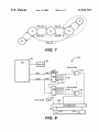
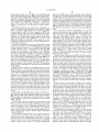
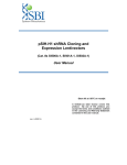
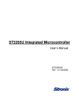
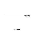
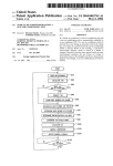
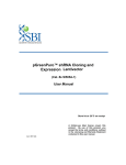
Referring to FIG. 2, a diagram of the audio CD ?rmWare
computer case in an open state With the display screen
visible to a user to alloW for certain volume adjustments
code 200 in the audio CD mode ROM 60 is shoWn. The 45 during music listening or alloW for track changes.
?rmWare 200 includes a mini-version of a poWer-on-self-test
In the present invention, the master volume control but
tons 35 alloWing for a single source of volume control Which
termed quick POST 202, a mini CD-ROM device driver 208,
is accessible While the portable computer case C is in a
an SMI-keyboard controller interface 206, and CD INIT
closed state. The master volume control buttons 35 are
204, the initialiZation code for the mini CD-ROM device
driver 208. While a conventional CD-ROM device driver in
digital and are preferably connected directly to the audio
chip 34. The volume up button and the volume doWn button
CD-ROM applications is RAM-based, the mini CD-ROM
device driver 208 in the audio CD mode ROM 60 is based
of the master volume control buttons 35 are hardWired
on a non-volatile memory such as read-only-memory
inputs to the audio chip 34.
(ROM). Also, While the CD-ROM device driver in a con
ventional CD-ROM application must alloW for playing of
audio and data CDs, the mini CD-ROM device driver 208 in
the audio CD mode ROM 60 alloWs for playing audio CDs,
not data CDs, thereby requiring less code and reducing the
55
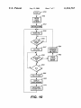
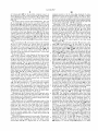
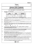
Turning to FIG. 10, a How chart of an alternate embodi
ment of the audio CD mode process in shoWn. The proce
dure commences With step 950. In step 952, the computer
system S enters the audio CD mode The precise implemen
tation for entering the audio CD mode is not considered
execution time for the device driver code. If a non-audio CD
critical to the present invention nor is the manner in Which
is present in the CD-ROM drive 28, the audio CD code
the audio CD is selected for play. In the disclosed embodi
opens the door of the CD-ROM drive 28 and generates a
beep to signal to the user that a non-audio CD is present in
the CD-ROM drive 28.
In an audio CD mode, a CD button selection is fetched by
a keyboard controller 46 in a keyboard controller embodi
ment of the present invention. A CD button selection, such
as a track selection, generates an SMI thereby executing the
ment the audio CD, if present, is automatically played upon
entry into the audio CD mode. Next, the computer system S
is initialiZed in step 954. In step 955, the computer system
S enters the PoWer-On-Suspend (POS) mode. In the POS
mode, the processor 10 clock is stopped. In this embodiment
of the invention, the computer system S remains in the POS
SMI handler code. The SMI-keyboard controller interface
65
mode until one of tWo Wake-up events occur. The ?rst
Wake-up event occurs When an external SMI is generated.
6,116,767
7
8
The second Wake-up event occurs every 500 msec When the
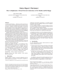
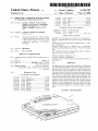
open state is shoWn. Since a conventional CD-ROM drive
Real Time Clock (RTC) generates a periodic signal. The
application Was dependent upon an operating system, it Was
computer system determines if a Wake-up event has
occurred in step 956. If no Wake-up event is detected, the
computer system continually loops at this step until a
Wake-up event occurs. If the computer system experiences a
necessary to use a conventional display screen to visually
indicate to a user When a CD-ROM drive application Was
being operated. As such, portable computer users have been
required to maintain a portable computer case containing a
portable computer in an open state (With the mini LCD
Wake-up event, the computer system exits the POS mode in
step 957. Once the computer system S has Wakened, the
processor 10 begins checking for either an external SMI
visible) to indicate the status of a conventional CD-ROM
drive application to the user.
status or a RTC periodic signal.
Speci?cally, the processor 10 in step 958 determines if the
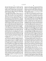
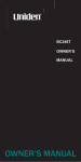
In contrast, With the present invention, Whether the por
10
external SMI status signal re?ects an external SMI. An
table computer case C is maintained in a closed state or open
upon receipt of an external SMI signal, an SMI is not
state, a user is capable of determining When a computer
system S is in a secondary operational mode, such as a mode
for playing audio CDs in a CD-ROM drive independent of
an operating system. Further, the user is able to readily
ascertain track information. The portable computer case C
includes a top shell 404 housing a main display screen 406
generated. HoWever, the ISA Bridge 24 sets a hardWired
external SMI status signal upon receipt of the external SMI.
along With other components and a bottom shell 408 housing
a key board 48 along With other components. The portable
If the external SMI status signal shoWs an external SMI Was
computer S of the present invention includes a status indi
cator 57 for indicating When the computer system S is in a
external SMI is generated by the keyboard controller 46
When a CD button selection occurs. This functions as a
Wake-up event as Well as a CD button selection. The ISA
Bridge 24 is implemented to disable the SMI generator, so
15
generated by the keyboard controller 46, the processor 10, in
secondary operational mode and a track indicator 61 for
indicating Which track of the audio CD is being played in the
step 962, calls the CD-ROM driver. The CD-ROM driver, in
step 964, addresses the SMI event, such as a track button
selection, before the computer system S returns to the POS
mode in step 955. If the external SMI status signal does not
shoW an external SMI, the processor 10 determines if the
RTC has generated the aforementioned 500 msec periodic
signal in step 960. If the RTC has not generated the 500 msec
periodic signal, then the processor returns to step 958.
If the 500 msec period signal is detected in step 962, the
processor 10 proceeds to step 966 and polls the CD-ROM
for status information such as the current track being played.
The processor 10 displays the track number if the track
number has changed since the last track number displayed in
step 968. Details of this step are provided in FIG. 3. The
process then proceeds to step 970 and saves the current
audio volume level to non-volatile RAM, such as Comple
mentary Metal Oxide Semiconductor (CMOS) memory. The
CD-ROM drive 28. The status indicator 57 and track indi
25
track indicator 61 are provided near the rear side edge 412
of the bottom shell 408 at a location near the bottom or rear
side edge 414 of the top shell 404. The location of the status
indicator 57, track indicator 61, and other control sWitches
and indicators on bottom shell 408 is preferably at or near an
area 409 Where the bottom shell 408 and top shell 404 are
pivotally connected to each other to open and close the case
C. The edge 414 of top shell 404 is recessed or removed at
a central portion 405 in the area 407 to permit vieWing of the
35
status indicator 57 and track indicator 61 Whether the case C
is open (FIG. 4) or closed (FIG. 5). Also, the status indicator
saved audio volume level is retrieved upon the next entry
into the audio CD mode. The process then returns to step 955
and re-enters POS mode. The disclosed embodiment shoWs
a 500 msec periodic signal. HoWever, according to the
57 and track indicator 61 are preferably provided on an
upWardly angled or ramp portion 400 of the top surface 410
techniques of the invention, a Wide variety of periods could
be implemented.
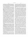
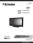
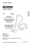
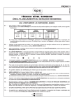
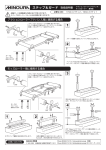
Referring to FIG. 3, the process for displaying the audio
disk track number (step 968 of FIG. 10) on the mini LCD is
shoWn. The process starts With step 300. In step 303, the
computer system S determines if a CD-ROM is present in
cator 61 (FIGS. 4—6) are provided on the top surface 410 of
the bottom shell 408 of the portable computer case C.
In the preferred embodiment, the status indicator 57 and
45
the CD-ROM drive 28. If no CD-ROM is present, the
computer system S proceeds to step 310 and displays the
battery gauge status before ending the process in step 312.
If a CD-ROM is present in step 303, the computer system
proceeds to step 304 Where the computer system determines
so that the status indicator 57 and track indicator 61 may be
easily seen by a user. It should be understood, hoWever, that
other locations on the bottom shell 408 Which provide
convenient vieWing for a user might be used, and precise
placement is not considered critical to the invention.
For a computer system S capable of playing audio CDs in
a CD-ROM drive 28 independent of an operating system, the
track indicator 61 is preferably a number ranging from 1—20.
The track indicator 61 is provided to the user on the mini
status display screen 55, Which is preferably of a liquid
crystal composition. When the computer system S is in an
audio CD mode, a pixel pattern corresponding to the track
present is not an audio CD-ROM, the computer system
indicator 61 value is displayed on the status display screen
55. The track indicator is preferably updated at a 500 msec
interval. HoWever, this is illustrative of the disclosed
proceeds to step 310 and displays the battery gauge status
before ending the process in step 312. If the CD-ROM
present is an audio CD-ROM, the computer system proceeds
embodiment and the techniques of the present invention
could be implemented With a Wide variety of indicators and
could be updated at a variety of intervals.
if the CD-ROM is an audio CD-ROM. If the CD-ROM
to step 305 to determine if the audio CD-ROM is being
played. If the audio CD-ROM is not being played, the
computer system again proceeds to step 310 and displays the
battery gauge status before ending the process in step 312.
If the audio CD-ROM is being played, then the computer
system displays the track number in step 306 if the track
number has changed since previously displayed. The track
number is displayed by sending a command and the current
track number being played to the keyboard controller 46,
Which updates the number on the display. The process ends
With step 312.
Referring to FIG. 4, an isometric vieW of the portable
computer case C that contains the computer system S in an
55
When the computer system S is in an audio CD mode, a
number corresponding to the track is displayed on the status
display screen 55. When the computer system S is in a
primary operational mode, the track indicator 61 is not
displayed on the status display screen 55. Thus, the track
indicator 61 serves as a visual cue to the user. It should be
65
understood that the track indicator 61 alternatively may
include track numbers for indicating a secondary operational
mode and battery charge status When in a primary opera
tional mode. A battery charge status display is disclosed in
co-pending US. Patent Application entitled “REAL-TIME
BATTERY GAUGE DISPLA ,” incorporated by reference
above. An enlarged vieW of a portion of the top surface 410
6,116,767
9
10
of bottom shell 408 of the portable computer case C is
shoWn in FIG. 6. Thus, it can be seen that the status display
screen 55 displaying the track indicator 61 is visible to the
user Whether the computer case C is open (FIG. 4) or closed
computer system to the S2 state. Also, from the S3 state,
toggling the poWer control sWitch PWRiSW 58 to a logical
state of “1” places the computer system S in the S1 state.
From the S1 state, the computer system S may also be placed
(FIG. 5).
in an S 4 state such as the sleep mode of the computer system
The master volume control buttons 35 (FIGS. 1. 4, 5, and
6) are preferably located on the top surface 410 of the
bottom shell 408 of the portable computer case C at or near
the locations described above for the status indicator 57. In
this Way, a user is capable of adjusting volume control With
buttons 35 during a secondary operational mode. This can be
done Without the need to open the portable computer case C
10
the audio CD mode sWitch DMiSW 56 so that the keyboard
controller 46 may detect the status of the audio CD mode
sWitch DMiSW 56. Based on the status of the audio CD
to visualiZe on the main display screen 406 the CD mixer
volume controls for the audio sources. Along With the status
indicator 57 and master volume control buttons 35, other CD
control buttons such as play/pause 420, stop 422, previous
S. In the sleep mode of the computer system S, the audio CD
mode control sWitch DMiSW 56 is disabled.
Referring to FIG. 8, a schematic diagram of the mini
status display screen control circuitry 8 1 0 of the present
invention is shoWn. The control circuitry 8 1 0 is coupled
betWeen the keyboard controller 46 and the mini status
display screen 55. The keyboard controller 46 is coupled to
15
mode sWitch DMiSW 56 and other information provided to
track 424, and neXt track 426 are similarly located on the top
the keyboard controller 46, the keyboard controller 46
surface 410 of the bottom shell 408 of the portable computer
provides a plurality of control signals to the mini status
case C.
display screen 55.
The track indicator 61 and master volume control buttons
35, due to their location, are visible When the portable
In particular, the keyboard controller 46 generates a data
signal 806 communicated to the data input of serial-in,
parallel-out shift register 800. The keyboard controller 46
computer case C is closed (FIG. 5) as Well as open (FIG. 4).
The audio CD mode control sWitch DMiSW 56 is also
provided on the top surface 410 of the bottom shell 408 such
that the audio CD mode control sWitch DMiSW 56 is
accessible to the user When the computer case C is in an open
state or a closed state.
25
Referring to FIG. 7, a state diagram of the poWer control
states of the portable computer system S is shoWn. The
poWer control states are controlled by the keyboard control
ler 46 for the keyboard controller embodiment of the present
invention. The Slstate is the normal “on” poWer state of the
computer system. The S, state corresponds to the poWer
control sWitch PWRiSW 58 having a logical state of “1.”
In the S1 state, the audio CD mode control sWitch DMiSW
screen 55 through an LCD connector 804 to generate
separate activation signals for segments of the mini status
display screen 55. In operation, data is clocked into the shift
registers 800 and 802 by the clock signal 808, and is thereby
converted to parallel data. By using the keyboard controller
86 to generate a data signal 806 and a clock signal 808, only
tWo pins from the keyboard controller 46 need to be dedi
cated to the operation of the mini status display screen 55.
56 for the secondary operational mode computer system is
disabled such that toggling the sWitch DMiSW 56 has no
effect. HoWever, in the S2 state, the audio CD mode control
sWitch DMiSW 56 is enabled. When the poWer sWitch
PWRiSW 58 is sWitched to a “0” logical state correspond
ing to an “off” poWer state, the system is placed in the S2
poWer control state. An eXample of a poWer control mode
corresponding to the S2 poWer control state is a hibernate
mode of the computer system S.
In the S2 state, When the audio CD mode control sWitch
DMiSW 56 is sWitched to a “1” logical state, the computer
A plurality of the segments correspond to the portion of
35
other status indicators such as a battery gauge indicator.
preferably by using exclusive-OR gates 816. The outputs of
the eXclusive-OR gates 816 are thus referenced siXty times
a second. The outputs of the LCD connector 804 are also
modulated With an inverted version of the 60 HZ clock signal
45
Alternatively, the S3 poWer state can be omitted, and a
poWer state throttling doWn the processor 10 to the loWest
useful speed can be implemented. This poWer state uses the
loWest useful processor speed to conserve energy When a full
55
bridge 24. The audio CD code also places the computer
is processed. HoWever, When a CD beZel button is being
processed, the audio CD code places the computer system S
sWitch DMiSW 56 to a logical state of “0” returns the
display the proper track number. The ONE digit 900 either
displays a “1” or it is blanked. The ONE digit 900 displays
the ZERO digit 904 is blanked. The X digit 902 displays the
numbers 0 through 9. The X digit 902 corresponds to the
in the S3 poWer control state. The S5 poWer state is a
poWer-on-suspend (POS) mode in Which the processor 10
clock is stopped.
From the S3 state, toggling the audio CD mode control
digit 904. The disclosed embodiment shoWs that track
numbers 1 through 20 can be displayed When an audio disk
is being played and that the three digit areas can be utiliZed
to display the battery gauge status, including status in a
percent form, When an audio disk is not being played. To
accomplish this, the three digit areas are selectively used to
a “1” When the track number is 10 through 19 and the ONE
digit is blanked When the track numbers is 1 through 9 or 20.
The ZERO digit 904 displays a “0” or it is blanked. The
ZERO digit displays a “0” When the track number is 20, else
system S in the S5 poWer state after a CD button selection
While the computer system S is in an audio CD mode, the
system S is in either the S3 poWer state or the S5 poWer state.
through an inverter 818. This modulation prevents damage
to the elements of the mini status display screen 55.
Turning noW to FIG. 9, an enlarged vieW of the track
indicator 61 is shoWn. The track indicator 61 contains three
digit areas, a ONE digit 900, an X digit 902, and a ZERO
independent of an operating system. In the S3 poWer state,
the processor 10 clock performs at full speed.
speed processor 10 is not needed.
After poWer up of a secondary operation mode of the
computer system S the audio CD code places the computer
system S in the S5 poWer state using logic in the PCI-ISA
the mini status display screen 55 for displaying the track
indicator 61. Other segments may be used for displaying
Preferably, each of the output state lines 814 of the shift
registers 800 and 802 to be provided to the mini status
display screen 55 are intermittently illuminated. This may be
done by modulating the status lines 814 With a 60 HZ clock,
system S is placed in the S3 poWer control state. The S3
poWer control state corresponds to the normal poWer state
for a secondary operational mode of a computer system S
such as a mode for playing audio CDs in a CD-ROM drive
also generates a clock signal 808 that is provided to the clock
inputs of shift registers 800 and 802. One of the output state
signals 812 of shift register 800 is provided as an input to
shift register 802. The other output state lines 814 of the shift
registers 800 and 802 are provided to the mini status display
track number When the track number is 1—9. When the track
number is 10—19, the X digit 902 displays 0 through 9,
65
corresponding to the second digit in the track number.
Therefore, if track 13 is being played, then the ONE digit
900 displays a “1” and the X digit 902 displays a “3”. When
6,116,767
11
12
the track number is 20, the X digit 902 displays a “2”.
bottom shell Wherein the audio disk track number indicator
is displayed on the status display.
Therefore, if track 20 is being played, then the X digit 902
displays a “2” and the ZERO digit 904 displays a “0”. While
6. The portable computer system of claim 5, Wherein the
status display is a liquid crystal display.
7. The portable computer system of claim 5, Wherein the
status display is con?gured to display disk track numbers
displaying the track number using this system illustrative of
the disclosed embodiment, display techniques according to
the invention could be implemented by a Wide variety of
other displays.
Thus, in a computer system according to the invention a
user is capable of vieWing a track indicator 61, status
indicator 57, and accessing master volume control buttons
35 and a control sWitch 56 for a secondary operational mode
1—20.
8. The portable computer system of claim 7, Where in the
status display further comprises:
10
When the computer case is in either an open state or a closed
displaying a blank;
state. A user, therefore, is not required to maintain the case
in an open state to determine current track information, and
the computer system is capable of functioning more like a
consumer audio CD player.
15
The foregoing disclosure and description of the invention
are illustrative and explanatory thereof, and various changes
portable computer system comprising:
10—19 are played, and the second digit area displaying
“2” When disk track number 20 is played;
a third digit area to the right of the second digit area, the
third digit area displaying a “0” When disk track
number 20 is played, else the third digit area displaying
a blank.
25
information during predetermined periods in Which the
audio disk is not being played.
10. The portable computer system of claim 9, Wherein the
additional status information comprising battery charge sta
portable computer case comprising:
number being played in the disk drive.
2. The portable computer system of claim 1, Wherein the
audio disk track number indicator is located on the bottom
shell at a location visible to a user Whether the portable
computer case is in the closed position or the portable
computer case is in the open position.
3. The portable computer system of claim 1, further
comprising a keyboard controller coupled to the status
9. The portable computer system of claim 5, Wherein the
audio disk track number indicator provides additional status
a disk drive; and
a portable computer case coupled to the disk drive, the
a top shell for housing a main display screen;
a bottom shell coupled to the top shell for housing a
keyboard and a processor, the top shell being movable
betWeen an open position and a closed position relative
to the bottom shell; and
an audio disk track number indicator provided on the top
surface of the bottom shell for indicating the track
a second digit area to the right of the ?rst digit area, the
second digit area displaying a number “1” through “9”
When corresponding disk track numbers 1—9 are
played, the second digit area displaying a number “0”
through “9” When corresponding disk track numbers
in the siZe, shape, materials, components, circuit elements,
Wiring connections and contacts, as Well as in the details of
the illustrated circuitry and construction and method of
operation may be made Without departing from the spirit of
the invention.
What is claimed is:
1. A portable computer system adapted to provide an
indication of an audio disk track number being played, the
a ?rst digit area displaying a “1” When the disk track
numbers 10—19 are played, else the ?rst digit area
tus information.
11. Aportable computer case adapted for visibly provid
ing an audio disk track number indicator to a user, compris
ing:
35
a loWer shell containing a keyboard and a processor;
an upper shell containing a main display screen coupled
to the loWer shell and movable betWeen an open
position and a closed position relative to the loWer
shell; and
an audio disk track number indicator integrated into the
loWer shell, Wherein the upper shell is recessed at an
area correspondingly located With the audio disk track
number indicator so that the audio disk track number
display, the keyboard controller generating control signals
indicator is visible to a user When the upper shell is in
for the status display.
4. The portable computer system of claim 1, Wherein the
disk drive is a Compact Disk Read Only Memory (CD
the closed position.
ROM) drive.
12. The portable computer case of claim 11, Wherein the
area located With the audio disk track number indicator
comprises a ramp surface of the loWer shell.
5. The portable computer system of claim 1, further
comprising a status display formed in the top surface of the
*
*
*
*
*