1
NAPOPC DA Server User’s Manual
User's Manual
[For Windows 95/98/Me/NT/2000/XP]
(Supports 7000, 8000, 87000 series modules and modbus controllers)
OPC®, the OPC-Logo and OPC™ Foundation are trademarks of the OPC Foundation.
(www.opcfoundation.org)
Microsoft®, Microsoft .NET™, VisualStudio.NET™ and Microsoft Windows™ are trademarks of the
Microsoft Corporation (www.microsoft.com)
Ver: 3.09
Date: Oct-10-2008
Page: 1
NAPOPC DA Server User’s Manual
Table of Contents
1
2
3
4
5
NAPOPC DA Server...........................................................................................................4
1.1 Installing NAPOPC DA Server ....................................................................................5
1.2 File ................................................................................................................................6
1.3 Searching Modules .......................................................................................................9
1.4 Monitoring Devices ....................................................................................................12
1.5 Adding A New Device ...............................................................................................14
1.5.1 Adding A New I-7K/I-8K/I-87K I/O Module .....................................................14
1.5.2 Adding A New Modbus TCP Controller .............................................................16
1.5.3 Adding A New Modbus RTU Controller ............................................................18
1.5.4 Adding A New Quicker/UPC Controller.............................................................21
1.6 Adding A New Group.................................................................................................23
1.7 Adding A New Tag.....................................................................................................24
1.7.1 Adding A New Tag for I-7K/I-8K/I-87K I/O Module.........................................24
1.7.2 Adding A New Tag For Controller......................................................................26
1.7.3 Scaling Settings....................................................................................................28
1.8 Adding Multi Tags for Modbus Device .....................................................................30
1.9 Expand/ Shrink Devices .............................................................................................31
1.10
Read/Write Tags......................................................................................................31
1.11
Editing A Device/Group/Tag Properties .................................................................33
1.12
Deleting A Device/Group/Tag ................................................................................33
1.13
Generating Tags ......................................................................................................34
1.14
Configurate Initial Status ........................................................................................35
1.15
Help .........................................................................................................................35
1.16
About.......................................................................................................................36
Quick Start.........................................................................................................................38
Connect To OPC Server....................................................................................................39
3.1 Optimize Your Communication .................................................................................39
3.2 VB5 Client Demo Program ........................................................................................42
3.3 .Net Client Demo Program .........................................................................................45
3.4 FactorySoft's Client Program .....................................................................................47
3.5 LabVIEW....................................................................................................................49
3.6 NATIONAL INSTRUMENTS...................................................................................51
3.7 WIZCON ....................................................................................................................56
3.8 iFix..............................................................................................................................62
3.9 InduSoft ......................................................................................................................67
3.10
Citect SCADA.........................................................................................................74
Remote Accessing .............................................................................................................94
4.1 System Requirement...................................................................................................95
4.2 Configuring DCOM....................................................................................................96
4.2.1 Configuring On the Server Site (Windows NT 4.0) ............................................97
4.2.2 Configuring On the Client Site (Windows 98) ..................................................102
4.2.3 Configuring On the Server Site (Windows 2000)..............................................107
4.2.4 Configuring On the Client Site (Windows XP) .................................................113
Writing Client Program with VB ....................................................................................117
5.1 Programming with VB5............................................................................................117
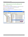
5.1.1 Overview of OPC & VB ....................................................................................117
5.1.2 Tools You Will Need to Build Your VB Client ................................................118
5.1.3 Building Your VB Client – Step By Step ..........................................................118
Ver: 3.09
Date: Oct-10-2008
Page: 2
NAPOPC DA Server User’s Manual
5.2 Programming with .Net ............................................................................................121
5.2.1 Limitations about .Net client programming.......................................................121
5.2.2 Tools – You Need to Build Your .Net Client ....................................................122
5.2.3 Building Your VB.Net Client – Step By Step ...................................................122
5.2.4 Building Your VC#.Net Client – Step By Step .................................................126
6 NAPOPC Changes List ...................................................................................................129
6.1 New features of NAPOPC version 3.0 .....................................................................129
6.1.1 New IO Kernel...................................................................................................129
6.1.2 Customized Module/Device Polling Time.........................................................129
6.1.3 Multi-Thread Communication ...........................................................................129
6.1.4 Miscellaneous ....................................................................................................130
6.2 New features of NAPOPC version 3.09 ...................................................................130
6.2.1 Support Remote Procedure Call with Quicker/UPC..........................................130
6.2.2 Switch of Single-Thread and Multi-Thread.......................................................130
7 Reference.........................................................................................................................131
Ver: 3.09
Date: Oct-10-2008
Page: 3
NAPOPC DA Server User’s Manual
1
NAPOPC DA Server
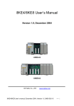
The NAPOPC DA Server uses an Explorer-style user interface to display a
hierarchical tree of modules and groups with their associated tags. A group can be
defined as a subdirectory containing one or more tags. A module may have many
subgroups of tags (see page 8). All tags belong to their module when they are
scanned for perform I/O. (The "OPC" stands for "OLE for Process Control" and the
"DA" stands for "Data Access".)
The following two figures show the difference between traditional mechanisms
and the OPC mechanism.
Figure 1-0-1 Traditional mechanisms used to access a device.
Ver: 3.09
Date: Oct-10-2008
Page: 4
NAPOPC DA Server User’s Manual
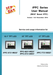
Figure 1-0-2 Using the OPC mechanism to access a device.
The main program of NAPOPC DA Server is "NAPOPCSvr.exe". It
automatically calls the "DCON_PC.DLL", "IOCtrl.DLL" and "UART.DLL" functions on
demand.
1.1
Installing NAPOPC DA Server
You can get the software from the “CD: \Napdos\Napopcsvr\” or you can
download it from http://www.icpdas.com/products/software/napopc/napopc.htm.
Hardware Requirement:
A personal computer with at least a Pentium, 133 MHz or faster processor
32 Mbytes ram (Preferably 64 Mbytes ram)
10 Mbytes hard disk free space
Software Requirement:
One of the following computer operating systems must be installed on your computer
system.
Windows 98
Windows ME/2000
Windows XP
Ver: 3.09
Date: Oct-10-2008
Page: 5
NAPOPC DA Server User’s Manual
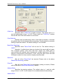
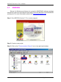
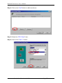
Double click the CD:\\Napdos\Napopcsvr\napopcdaserver.exe and follow the
installing wizard to finish the installation.
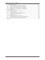
After you complete the above steps, you can start the NAPOPC Server by
clicking the “NAPOPC Server” as following.
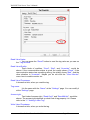
1.2
File
All configuration settings can be saved into configuration file by clicking the
"File/ Save” and "File/ Save As …” menu item. The OPC server will automatically
load the last configuration file with every launch.
New:
Clean current project and create a new project
Ver: 3.09
Date: Oct-10-2008
Page: 6
NAPOPC DA Server User’s Manual
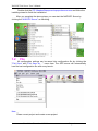
Open:
Load old NAPOPC project
Save:
Save current NAPOPC project
Ver: 3.09
Date: Oct-10-2008
Page: 7
NAPOPC DA Server User’s Manual
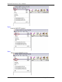
Save as…:
Save NAPOPC project as a new one
Print Setup:
Choose and setup printer
Print Preview:
Preview current modules list
Ver: 3.09
Date: Oct-10-2008
Page: 8
NAPOPC DA Server User’s Manual
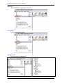
Print
Print current modules list
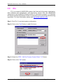
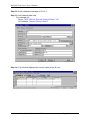
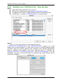
1.3
Searching Modules
The "Search Modules…" function lets you configure the OPC server
automatically. It searches the RS-232 and RS-485 network to find modules and then
generates tags automatically. This function generates AI/AO, DI/DO, Latched DI and
Counter tags. Please refer to a “MODULES.HTM” file in \\ICPDAS\NAPOPC folder.
NOTE:
For complete module support, please update ”\ICPDAS\NAPOPC\module.ini”
from http://www.icpdas.com/products/Software/NAPOPC/napopc.htm
frequently.
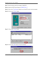
Step 1: Click on the "Add/ Search Modules…" menu item or the
for modules.
icon to search
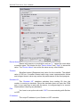
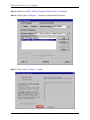
Step 2: The "Search Modules" dialog box pops up.
Ver: 3.09
Date: Oct-10-2008
Page: 9
NAPOPC DA Server User’s Manual
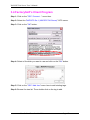
COM Port:
Specifies which "COM Port" number is search. The default value is 1
and the valid range is from 1 to 255. Please verify the "COM Port" number
that the RS-232 or RS-485 network is connected.
Clear Modules:
Modules can be added many times. If this field is checked, it removes
all modules from the list window before searching. Checking this box prevents
adding a duplicate module. The default setting is "not checked".
Baud Rate Searching:
Specifies which "Baud Rate" will be look for. The default setting is
“9600".
Naturally, if multiple baud rates are checked, the search will be longer.
The computer system must close and then reopen the COM ports to
communicate with modules when searching for multiple baud rates. This also
reduces communication performance. Thus, using the same baud rate and
COM port number for every module is highly recommended.
Select All:
Sets all of the "Baud Rate" be checked. Please refer to the above
"Baud Rate Searching" section.
Clear All:
Sets all of the "Baud Rate" be unchecked (nothing to search). Please
refer to the above "Baud Rate Searching" section.
Address/Start:
Specifies the starting address. The default value is 1 and the valid
range is from 1 to 255. It won't search for an address below these settings.
Address/End:
Ver: 3.09
Date: Oct-10-2008
Page: 10
NAPOPC DA Server User’s Manual
Specifies the ending address. The default value is 255 and the valid
range is from 1 to 255. It won't search for an address greater than these
settings.
Checksum/Disabled:
If this field is checked, modules are searched with no checksum. If both
the "Disabled" and "Enabled" fields were unchecked, the search would be
undefined.
Checksum/Enabled:
If this field is checked, it searches modules with checksum. If both the
"Disabled" and "Enabled" fields were unchecked, again, the search would be
undefined.
Timeout:
Specifies the communicate timeout value for each module. The default
value is 500 (equal to 0.5 Seconds), measured in millisecond(s) [0.001
Second(s)]. After a module has been found, this timeout value will also be
recorded for further use.
Users can reduce this value to shorten the search time. Be careful. A
shorter search time may cause communication failure.
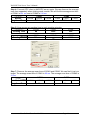
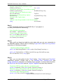
Status:
It shows the searching status (includes: progress in %, Address in
"A:??”, Baud-Rate in "B:????", Checksum in "S:?" and Error-Code in "EC:??").
The timeout error code is 15. In most cases, it indicates no module has
responded to the current command.
Search:
After setting the above options, click this button to search. The window
will be closed automatically when completed.
Stop:
During the search, users can click the button to stop. The window will
stay on the screen after the search is cancelled.
Exit:
Users can click the button to close the window.
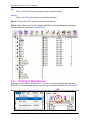
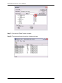
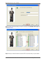
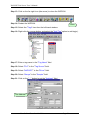
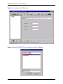
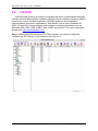
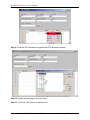
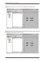
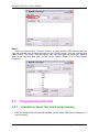
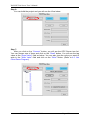
Step 3: After the search, the discovered modules will be listed on the DeviceWindow (left side). Users can also see the tags on the Tag-Window (right
side) generated by the "Search Modules…" function automatically.
Ver: 3.09
Date: Oct-10-2008
Page: 11
NAPOPC DA Server User’s Manual
Device-Window
Tag-Window
The "Search Modules…" function generates "Digital Input", "Digital Output"
"Bit Input" or "Bit Output" tags.
The "Digital Input" and "Digital Output" tags use one communication to read
the status of all channels, while the "Bit Input" and "Bit Output" tags use one
communication to read only one-channel status. The "Digital Input" and "Digital
Output" tags have better performance than the "Bit Input" and "Bit Output" tags.
Using the "Digital Input" and "Digital Output" tags to access modules is highly
recommended.
Groups
Tags
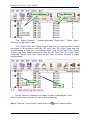
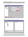
1.4
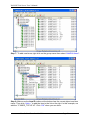
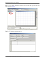
Monitoring Devices
Use the "Monitor" function to see values of tags by checking the "View/
Monitor" menu item. Uncheck the item to stop monitoring.
Step 1: Click the "View/ Monitor" menu item or the
Ver: 3.09
Date: Oct-10-2008
icon to enable monitor.
Page: 12
NAPOPC DA Server User’s Manual
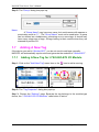
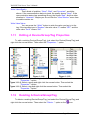
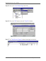
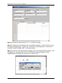
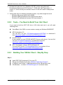
Step 2: Select the "DIs" group in the Device-Window (left side) to monitor its own Bit
-Input tags.
Step 3: Select the "7050D" module on the Device-Window to monitor its own DigitalInput and Digital-Output tags.
Ver: 3.09
Date: Oct-10-2008
Page: 13
NAPOPC DA Server User’s Manual
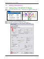
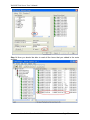
1.5
1.5.1
Adding A New Device
Adding A New I-7K/I-8K/I-87K I/O Module
Step 1: Click on the "Add/ New Device…" menu item or the
module.
icon to add a new
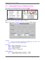
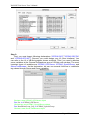
Step 2: The "Device Properties" dialog box pops up.
Step 3: Click the "I-7K/I-8K/I-87K I/O Modules" radio button.
Step 4: Click the "No Controller" or “With Controller” radio button.
Ver: 3.09
Date: Oct-10-2008
Page: 14
NAPOPC DA Server User’s Manual
Device Name:
Names with spaces or punctuation such as “|!.,” cannot be used within
a module name. The clients use the "Device Name" and "Tags" to access its
value. The "Device Name" can not be the same as any other module.
7K/ 87K/ 8K/ Controller Module ID:
User can click on the Combo Box to select a Module ID.
Address:
Specifies a Module Address for this module. The default value is 1 and
the valid range is between 1 to 255.
This field is disabled for the 8000 sub-devices. It will use the 8000
main-device’s address.
Timeout:
Specifies timeout (Response time) value for this module. The default
value is 200 ms. A smaller timeout value may cause communication failure
and a greater timeout value may reduce the performance of the client
program.
This field is disabled for the 8000 sub-devices and it will use the 8000
main-device’s timeout value.
Slot:
The 8000 main-device has 4 or 8 slots for the 8000 sub-device to plug
in. This “slot” field indicates the slot number that the 8000 sub-device is using.
The valid range is from 0 to 7.
This field is disabled for 8000 main-device and 7000 series modules.
Checksum:
This checksum field must match the hardware setting. A mismatch will
always cause a communication failure with this module.
This field is disabled for the 8000 sub-devices and it will use the 8000
main-device’s checksum.
COM Port:
Specifies the COM port to be used. Please verfiy which COM port
number that the RS-232 / RS-485 network is using. Wrong settings will always
cause communication failure.
This field is disabled for the 8000 sub-devices. It will use the 8000 main
controller unit COM port setting.
Baud Rate:
Specifies the baud rate to be used. Verify the module's current baud
rate. A wrong setting will always cause communication failure for this module.
This field is disabled for the 8000 sub-devices. It will use the 8000
main-controller unit baud rate.
Simulate I/O:
The “Simulate I/O” checkbox switches from reading I/O from the
module to running a simulator. Since the simulator does not open the COM
Ver: 3.09
Date: Oct-10-2008
Page: 15
NAPOPC DA Server User’s Manual
port, it is an easy way to work with the server, to configure tags or to connect
clients without requiring any hardware. This field is disabled and not used for
the 8000 main controller unit.
Pending Time:
Minimum interval time between two access. To activate this function,
NAPOPC can work under optimized communication performance. If this
module only needs to be accessed 1 time per 5 seconds. You can set
pending time as 5000 ms. NAPOPC will automatically spread time resource
to other modules which are connected with each other.
OK:
Click on the "OK" button to add the new module setting.
Cancel:
Click on the "Cancel" button to avoid any changes.
Step 4: Click on the "OK" button to add this new module.
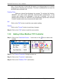
1.5.2
Adding A New Modbus TCP Controller
Step 1: Click on the "Add/ New Device…" menu item or the
module.
icon to add a new
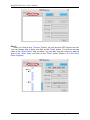
Step 2: The "Device Properties" dialog box pops up.
Step 3: Click on the "Controller" radio button.
Step 4: Click on the "Modbus TCP" radio button.
Ver: 3.09
Date: Oct-10-2008
Page: 16
NAPOPC DA Server User’s Manual
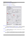
Device Name:
Names with spaces or punctuation such as “|!.,” cannot be used within
a module name. The clients use the "Device Name" and "Tags" to access its
value. The "Device Name" can not be the same as any other module.
Address:
Specifies a Address for this controller. The default value is 1 and the
valid range is between 1 to 247.
Timeout:
Specifies timeout (Response time) value for this controller. The default
value is 200 ms. A smaller timeout value may cause communication failure.
Port:
You have to set up the value with “502” for communicating with I7188EG or I-8437/I-8837.
IP Address:
The uniqe IP address of your Modbus TCP controller.
Ver: 3.09
Date: Oct-10-2008
Page: 17
NAPOPC DA Server User’s Manual
Word Swap:
The “Word Swap” checkbox switches the interpretation of 4 Byte
values. Sometimes we need to make the checkbox “TRUE” in order to
achieve the purpose of Lo-Hi/Hi-Lo communication.
Simulate I/O:
The “Simulate I/O” checkbox switches from reading I/O from the
module to running a simulator. Since the simulator does not open the TCP/IP
port, it is an easy way to work with the server, to configure tags or to connect
clients without requiring any hardware.
Request Tag Number:
The “Requested Tag Number” sets tag value numbers that each
command will get from device. For ISAGrAF, it should less than 124 for coil
and register. For 7188MTCP, it should less than 498 for coil and 127 for
register. The default numbers are both 122. (For Modbus standard, it can’t
greater than 2000 for coil and 127 for register.
Pending Time:
Minimum interval time between two access. To activate this function,
NAPOPC can work under optimized communication performance. If this
module only needs to be accessed 1 time per 5 seconds. You can set
pending time as 5000 ms. NAPOPC will automatically spread time resource
to other modules which are connected with each other.
OK:
Click on the "OK" button to add the new controller setting.
Cancel:
Click on the "Cancel" button to avoid any changes.
Step 5: Click on the "OK" button to add this new device.
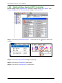
1.5.3
Adding A New Modbus RTU Controller
Step 1: Click on the "Add/ New Device…" menu item or the
module.
Ver: 3.09
Date: Oct-10-2008
icon to add a new
Page: 18
NAPOPC DA Server User’s Manual
Step 2: The "Device Properties" dialog box pops up.
Step 3: Click on the "Controller" radio button.
Step 4: Click on the "Modbus RTU" radio button.
Device Name:
Names with spaces or punctuation such as “|!.,” cannot be used within
a module name. The clients use the "Device Name" and "Tags" to access its
value. The "Device Name" can not be the same as any other module.
Address:
Specifies a Address for this controller. The default value is 1 and the
valid range is between 1 to 247.
Timeout:
Specifies timeout (Response time) value for this controller. The default
value is 200 ms. A smaller timeout value may cause communication failure
and a larger timeout value may reduce the performance of the client program.
Ver: 3.09
Date: Oct-10-2008
Page: 19
NAPOPC DA Server User’s Manual
Msg Delay:
Specifies message delay value for this controller. The default value is 0
ms. A smaller msg delay value may have a higher system loading, but it will
have a faster data exchange speed.
Word Swap:
The “Word Swap” checkbox switches the interpretation of 4 Byte
values. Sometimes we need to make the checkbox “TRUE” in order to
achieve the purpose of Lo-Hi/Hi-Lo communication.
COM Port:
Specifies the COM port to be used. Please verfiy which COM port
number that the RS-232 / RS-485 network is using. Wrong settings will always
cause communication failure.
Baud Rate:
Specifies the baud rate to be used. Verify the module's current baud
rate. A wrong setting will always cause communication error for this controller.
Simulate I/O:
The “Simulate I/O” checkbox switches from reading I/O from the
module to running a simulator. Since the simulator does not open the COM
port, it is an easy way to work with the server, to configure tags or to connect
clients without requiring any hardware.
Pending Time:
Minimum interval time between two access. To activate this function,
NAPOPC can work under optimized communication performance. If this
module only needs to be accessed 1 time per 5 seconds. You can set
pending time as 5000 ms. NAPOPC will automatically spread time resource
to other modules which are connected with each other.
Request Tag Number:
The “Requested Tag Number” sets tag value numbers that each
command will get from device. For ISAGrAF, it should less than 124 for coil
and register. For 7188MTCP, it should less than 498 for coil and 127 for
register. The default numbers are both 122. (For Modbus standard, it can’t
greater than 2000 for coil and 127 for register.
ISaGRAF:
Connect control with run ISaGraf firmware
M-7K:
Connect M7K module
OK:
Click on the "OK" button to add the new controller setting.
Cancel:
Click on the "Cancel" button to avoid any changes.
Step 5: Click on the "OK" button to add this new device.
Ver: 3.09
Date: Oct-10-2008
Page: 20
NAPOPC DA Server User’s Manual
1.5.4
Adding A New Quicker/UPC Controller
Before adding a new “Quicker/UPC” controller, please check “RPC Server” and
“Active ScanKernel” at “Services Setup” dialog of “Quicker/UPC”.
Step 1: Click on the "Add/ New Device…" menu item or the
module.
icon to add a new
Step 2: The "Device Properties" dialog box pops up.
Step 3: Click on the "Controller" radio button.
Step 4: Click on the "Quicker/UPC" radio button.
Ver: 3.09
Date: Oct-10-2008
Page: 21
NAPOPC DA Server User’s Manual
Device Name:
Names with spaces or punctuation such as “|!.,” cannot be used within
a module name. The clients use the "Device Name" and "Tags" to access its
value. The "Device Name" can not be the same as any other module.
Timeout:
Specifies timeout (Response time) value for this controller. The default
value is 200 ms. A smaller timeout value may cause communication failure
and a larger timeout value may reduce the performance of the client program.
Simulate I/O:
The “Simulate I/O” checkbox switches from reading I/O from the
module to running a simulator. Since the simulator does not open the COM
port, it is an easy way to work with the server, to configure tags or to connect
clients without requiring any hardware.
Port:
You have to set up the value with “505” for communicating with Quicker
or UPC.
IP Address:
The uniqe IP address of your Quicker or UPC controller.
Ver: 3.09
Date: Oct-10-2008
Page: 22
NAPOPC DA Server User’s Manual
OK:
Click on the "OK" button to add the new controller setting.
Cancel:
Click on the "Cancel" button to avoid any changes.
Step 5: Click on the "OK" button to add this new device.
Step 6: After clicking on the “OK” button, NAPOPC will automatically synchronize
and generate the modules of “Quiker/UPC”.
1.6
Adding A New Group
If the device you add is “Quicker/UPC”, you do not need to add groups manually.
NAPOPC will automatically synchronize and generate the modules of “Quiker/UPC”.
Step 1: Click on the "Add/ New Group" menu item or the
Ver: 3.09
Date: Oct-10-2008
icon to add a new group.
Page: 23
NAPOPC DA Server User’s Manual
Step 2: The "Group" dialog box pops up.
Name:
A "Group Name" may have any name, but avoid names with spaces or
punctuation such as “|!.,”. The "Group Name" must not be used twice. A group
can be defined as a subdirectory containing one or more tags. A device may
have many subgroups of tags. All tags belong to their module when they are
scanned to perform I/O.
1.7
Adding A New Tag
If the device you add is “Quicker/UPC”, you do not need to add tags manually.
NAPOPC will automatically synchronize and generate the modules of “Quiker/UPC”.
1.7.1
Adding A New Tag for I-7K/I-8K/I-87K I/O Module
Step 1: Click on the "Add/ New Tag" menu item or the
icon to add a new tag.
Step 2: The "Tag Properties" dialog box pops up.
Step 3: Choose the “Settings” page. Because the tag belongs to the module-type
device, the “I-7K/I-8K/I-87K I/O Modules” radio button is active.
Ver: 3.09
Date: Oct-10-2008
Page: 24
NAPOPC DA Server User’s Manual
Name:
Any "Tag Name" may be used, but avoid names with spaces or
punctuation such as “|!.,”. The clients will use the "Device Name" and "Tags"
to access its value. Hence the "Tag Name" cannot be a duplicate of another
tag in the same group.
Description:
Specifies the description text for this tag. This can be blank.
Type:
Specifies the command to be used for this tag. Different modules
support different commands. For commands, please refer to a
“MODULES.HTM” file in \\ICPDAS\NAPOPC folder
Channel:
Specifies the channel number to be used for this tag. The "Digital Input"
and "Digital Output" tags do not use this channel setting, because all channels
are read with one communication.
Simulation signal:
The valid signal is SINE, RAMP and RANDOM. This field is validated
when the module uses simulation I/O. Please refer to the "Adding A New
Device" section.
Ver: 3.09
Date: Oct-10-2008
Page: 25
NAPOPC DA Server User’s Manual
OK:
Click on the "OK" button to add the new tag setting.
Cancel:
Click on the "Cancel" button to avoid any changes.
Scaling:
Enable:
Check this check-box to enable the "Settings…" button.
Settings:
Click on this button to set the scaling feature.
For more information, please refer to the section "1.7.3 Scaling Settings".
1.7.2
Adding A New Tag For Controller
Step 1: Click on the "Add/ New Tag" menu item or the
icon to add a new tag.
Step 2: The "Tag Properties" dialog box pops up.
Step 3: Choose the “Settings” page. Because the tag belongs to the controller-type
device, the “Controller” radio button is active.
Ver: 3.09
Date: Oct-10-2008
Page: 26
NAPOPC DA Server User’s Manual
Name:
Any "Tag Name" may be used, but avoid names with spaces or
punctuation such as “|!.,”. The clients will use the "Device Name" and "Tags"
to access its value. Hence the "Tag Name" cannot be a duplicate of another
tag in the same group.
Description:
Specifies the description text for this tag. This can be blank.
Data:
Specifies the data type of this tag which’s location type is “Input
Register” or “Output Register”. NAPOPC Server support five kinds of data
type which are “Short”, “Long”, “Float”, “Word”, and “DWord”.
Data Type
Short
Long
Float
Word
DWord
Ver: 3.09
Definition
16-bit signed integer
32-bit signed integer
Floating-point variable
16-bit unsigned integer
32-bit unsigned integer
Date: Oct-10-2008
Range
-32768~32767
-2147483648~2147483647
-1.7E-308~1.7E+308
0~65535
0~4294967295
Page: 27
NAPOPC DA Server User’s Manual
Location:
Specifies the tag address. It must be the same with the the variable
address in the controller. Besides, you have to choose the location type. After
you choose the location number, there are four location types you can
choose.They are ”Input Coil”, “Output Coil”, “Input Register”, and “Output
Register”. When you monitor controller device(see 1.3 Monitoring Device), the
“Channel/Location” field will show a value according to the location and
location type as below.
Location Type
Output Coil
Input Coil
Input Register
Output Register
Range
000001 - 065536
100001 - 165536
300001 - 365536
400001 - 465536
Simulation signal:
The valid signal is SINE, RAMP and RANDOM. This field is validated
when the module uses simulation I/O. Please refer to the "Adding A New
Device" section.
OK:
Click on the "OK" button to add the new tag setting.
Cancel:
Click on the "Cancel" button to avoid any changes.
Scaling:
Enable:
Check this check-box to enable the "Settings…" button.
Settings:
Click on this button to set the scaling feature.
For more information, please refer to the section "1.7.3 Scaling Settings".
1.7.3
Scaling Settings
In general, the “Scaling” feature is only useful for the “floating-point” data type.
Ver: 3.09
Date: Oct-10-2008
Page: 28
NAPOPC DA Server User’s Manual
Raw Data:
Min: The original Minimum value. ([MinRaw])
Max: The original Maximum value. ([MaxRaw])
Scales to:
Units: The unit of the scaled value. (Just for reference only.)
Min: The scaled Minimum value. ([MinScale])
Max: The scaled Maximum value. ([MaxScale])
Conversion:
Linear:
Scaled Value = ((Original Value – [MinRaw]) / ([MaxRaw] – [MinRaw]))
* ([MaxScale] – [MinScale]) + [MinScale]
Square Root:
Scaled Value = ((sqrt (Original Value) – [MinRaw]) * ([MaxScale] – [MinScale]))
/ sqrt ([MaxRaw] – [MinRaw]) + [MinScale]
Deadband (%):
In general, please keep "0" in this field.
For more information, please refer to the "4.5.1.6 Percent Deadband"
section in the "OPCDA20_Cust.PDF" manual, page 68.
OK:
Click the "OK" button to save these settings.
Cancel:
Click the "Cancel" button to avoid any changes.
Ver: 3.09
Date: Oct-10-2008
Page: 29
NAPOPC DA Server User’s Manual
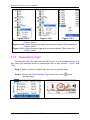
1.8
Adding Multi Tags for Modbus Device
This function only work when the device’s protocol is Modbus.
icon to add a new tag.
Step 1: Click on the "Add/ Multi Tags" menu item or the
Step 2: The "Add Multi Tags Dialog" dialog box pops up.
Step 3: Choose correct “Prototype” ,“Data Type” and key in Modbus address.
Prototype:
There are four kinds of prototype for modbus tag. “Coil Input”, “Coil
Output”, “Register Input” and “Register Output”.
Data Type:
“Short” : 16 bits, -32768 ~ 32767
“Long” : 32 bits, -2147483648. ~ 2147483647
“Float” : 32 bits, float numbers
“Word” : 16 bits, 0 ~ 65535
“DWORD” : 32 bits, 0 ~ 4294967295
Modbus Address:
“From” : modbus address number of start tag, 1 ~ 65535
“To”
: modbus address number of end tag. 1 ~ 65535
Ver: 3.09
Date: Oct-10-2008
Page: 30
NAPOPC DA Server User’s Manual
Separation:
Separation numbers between each tag. 1 ~ 100
OK:
Click on the "OK" button to add the new tag setting.
Cancel:
Click on the "Cancel" button to avoid any changes.
1.9
Expand/ Shrink Devices
Click on the “Edit/ Expand device (Shrink device)” menu item or the
icon to expand(shrink) all devices..
1.10
(
)
Read/Write Tags
First, you have to use the "Monitor" function to see values of tags by checking
the "View/ Monitor" menu item. Select a tag and right click the mouse button. Then
select the "Properties..." option. Choose the “Read & Write” page to read/write the
tag.
Step 1: Click the "View/ Monitor" menu item to enable monitor.
Step 2: Select a tag and right click the mouse button. Then select the "Properties.."
option.
Step 3: Choose the “Read & Write” page. You can see the “Tag name” and “Access
right” at the first. If the access right is “Read only!”, the write function is
disable.
Ver: 3.09
Date: Oct-10-2008
Page: 31
NAPOPC DA Server User’s Manual
Read Value/Value:
You can press the “Read!” button to read the tag value as you saw on
the “Tag-Window”.
Read Value/Quality:
Three kinds of qualities, “Good”, “Bad”, and “Uncertain”, would be
shown. If the communication status is good, the quality shows “Good”. If the
communication status has something wrong, the quality shows “Bad”. And the
other situation is “Uncertain”. Maybe you do not click the "View/ Monitor"
menu item to enable monitor etc.
Read Value/Timestamp:
It shows the time, when you read the tag.
Tag name:
It is the same with the “Name” at the “Settings” page. You can modify it
at the “Settings” page.
Access right:
Two kinds of aceess right, “Read Only!” and “Read&Write!”, would be
shown. The access right depends on what kind of tag property it is. Please
refer to the “1.7 Adding A New Tag”
Write Value/Timestamp:
It shows the time, when you write the tag.
Ver: 3.09
Date: Oct-10-2008
Page: 32
NAPOPC DA Server User’s Manual
Write Value/Quality:
Three kinds of qualities, “Good”, “Bad”, and “Uncertain”, would be
shown. If the communication status is good, the quality shows “Good”. If the
communication status has something wrong, the shows “Bad”. And the other
situation is “Uncertain”. Maybe you do not click the "View/ Monitor" menu item
to enable monitor etc.
Write Value/Value:
You can press the “Write!” button to write the value you key-in to the
tag. If the tag data type is “Boolean” the write value “0” means “OFF” and the
write value “not 0” means “ON”.
1.11
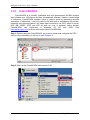
Editing A Device/Group/Tag Properties
To edit a existing Device(/Group/Tag), just select the Device(/Group/Tag) and
right click the mouse button. Then select the "Properties…" option.
Figure 1-11-3.
Figure 1-11-1.
Figure 1-11-2.
Figure 1-11-1. Select a device and right click the mouse button. Then select the
"Properties.." option.
Figure 1-11-2. Select a group and right click the mouse button. Then select the
"Properties.." option.
Figure 1-11-3. Select a tag and right click the mouse button. Then select the
"Properties.." option.
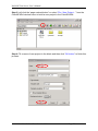
1.12
Deleting A Device/Group/Tag
To delete a existing Device/Group/Tag, just select the Device(/Group/Tag) and
right click the mouse button. Then select the "Delete…" option or the
Ver: 3.09
Date: Oct-10-2008
icon.
Page: 33
NAPOPC DA Server User’s Manual
Figure 1-12-2.
Figure 1-12-1.
Figure 1-12-3.
Figure 1-12-1. Select a device and right click the mouse button. Then select the
"Delete" option.
Figure 1-12-2. Select a group and right click the mouse button. Then select the
"Delete" option.
Figure 1-12-3. Select a tag and right click the mouse button. Then select the
"Delete" option.
1.13
Generating Tags
This function lets you easily test the OPC server in the simulation mode. It is
only valid if the selected device of module type has no sub “Module”, "Group" and
"Tag".
Step 1: Select a device of module type you want to generate tags.
Step 2: Click on the "Add/ Generate Tags" menu item or the
generate tags.
Ver: 3.09
Date: Oct-10-2008
icon to
Page: 34
NAPOPC DA Server User’s Manual
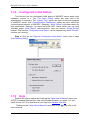
1.14
Configurate Initial Status
This function lets you configurate initial status of NAPOPC server when client
softwares connect to it. The “File Open Dialog” option lets user load a file
automatically or manually. The “System Tray” option can hide or minimize program
of NAPOPC server. And “Communication Mechanism” option lets user define the
communication behavior of NAPOPC. Generally, “Multi-Thread” is the best choice for
high performace. However, for some particular OPC clients which can not work
smoothly under “Multi-Thread” communication, user can choose “Single-Thread”
instead. This function, Configurate Initial Status, can be selected only when “Monitor”
function isn’t running.
Step 1: Click on the "Options/ Configurate Initial Status" menu item to open
“Initial Setting Dialog”.
1.15
Help
Refer to the user’s manual by Checking the "Help/ User’s Manual" menu item.
All PDF formatted files are best view using Acrobat Reader 5 or newer. You can
install it from our CD or download a free copy from Adobe's Web Site.
Clicking on the "Help/ User's Manual" menu item or the
user’s manual.
Ver: 3.09
Date: Oct-10-2008
icon refer to the
Page: 35
NAPOPC DA Server User’s Manual
Visit our web by checking the "Help/ ICP DAS Online" menu item or contact
us by checking the "Help/ Mail ICP DAS" menu item.
Click on the "Help/ ICP DAS Online" menu item or the
Click on the "Help/ Mail ICP DAS" menu item or the
1.16
icon to browse our web.
icon to contact us.
About
Click on the "Help/ About NAPOPCSvr…" menu item or the
icon to see the
"About NAPOPC DA Server" dialox box. It shows the version number.
Step 1: Click on the "Help/ About NAPOPCSvr…" menu item.
Step 2: The "About NAPOPC DA Server" window pops up.
Ver: 3.09
Date: Oct-10-2008
Page: 36
NAPOPC DA Server User’s Manual
Ver: 3.09
Date: Oct-10-2008
Page: 37
NAPOPC DA Server User’s Manual
2
Quick Start
Please follow these steps:
1. Wire Modules or Controllers.
Wire modules in the RS-232 / RS-485 network. (Refer to "\CD
\Napdos\7000\manual \GetStart.PDF" manual.)
Wire controllers to your PC.
2. Configure Modules or Controllers.
Use DCON Utility to set modules. (Refer to "\CD \Napdos\7000\manual
\GetStart.PDF" manual.)
Use ISaGRAF to configure the I-7188EG/XG or I-8xx7.
3. Install the OPC server.
Install the NAPOPC on your computer.
4. Run the OPC Server.
Launch the OPC server by executing " C:\ICPDAS\NAPOPC\NAPOPCSvr.exe"
5. Search Modules.
Refer to the "1.3 Search Modules…" section to search modules in the RS-485
network.
6. Add a new controller
Refer to the “1.5 Adding A New Device” section to add a new modbus RTU or
modbus TCP controller.
7. Save Configuration.
Save the configuration by clicking "File/Save" menu item.
8. Close OPC server.
Close OPC Server by clicking "File/Exit" menu item.
9. Connect to OPC server.
Run your client program and connect to our OPC server by linking
"NAPOPC.Svr" or " NAPOPC.Svr.1".
(Please refer to user's manual of your client software provided by your vendor.)
This forces the system to run the OPC server automatically in background.
Ver: 3.09
Date: Oct-10-2008
Page: 38
NAPOPC DA Server User’s Manual
3
Connect To OPC Server
The OPC is defined by the OPC Foundation, and any client program supporting
OPC can connect to OPC server (for example: Lab VIEW v5.0 and WIZCON 7.51).
Any computer language supporting the COM mechanism can also connect to the
OPC server directly through the COM interface.
The first section shows you how to optimize your communication. And the
following sections show you how to connect to OPC server by using client program
provided by Factory Soft, Inc, Lab VIEW, Server Explorer provided by National
Instruments, WIZCON, iFix, InduSoft and CitectSCADA. To connect to OPC server
by other OPC client, please refer to your OPC client user's manual.
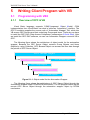
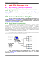
3.1
Optimize Your Communication
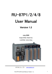
Figure 3.1.1 Communication architecture of I/O modules
Figure 3.1.1 is a figure of communication architecture of I/O modules. NAPOPC
server accesses to I-87024/I-87017/I-87058/I-7024/I-7033/I-7041 via serial COM port.
The assumed situation, we only need the interval time of accessing I-87024 and I7024 is 1 sec. The interval time of I-7041 and I-87058 is 3 sec. However, we want to
update I-7033 and I-87017 every 100 ms. For this purpose, we can achieve it by
seven steps as below.
Step 1: First of all, we try to connect all modules on COM1 and to auto search these
modules.
Ver: 3.09
Date: Oct-10-2008
Page: 39
NAPOPC DA Server User’s Manual
Step 2: Connect OPC client to NAPOPC Server. At the status bar of NAPOPC
window, it shows average scan time
when clicking any module.
We will find the average scan time is 968 ms.
COM1
Module
Avg Scan Time
I-87024
I-87017
I-87058
I-7033
I-7041
I-7024
968 ms
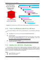
Step 3: We divide these modules into two groups. I-87024/I-87017/I-87058 connects
to COM1. I-7033/I-7041/I-7024 connects to COM2. And we search again.
Ver: 3.09
Date: Oct-10-2008
Page: 40
NAPOPC DA Server User’s Manual
Step 4: Connect OPC client to NAPOPC server again. We can discover the average
scan time separately when clicking each module. We will find the average scan time
of COM1 is 391 ms, and of COM2 is 516 ms.
COM 1
COM2
I-87024
I-87017
I-87058
I-7033
I-7041
I-7024
Module
Avg Scan Time
391 ms
516 ms
Step 5: Now we can set pending time to each module as below.
I-7033
I-7041
Pending Time
2000
─
Pending Time
I-87024
800
I-87017
─
I-7024
800
I-87058
2000
Step 7: Discover the average scan time of COM1 and COM2. We can find it is at our
target. The average scan time of COM1 is 62 ms. The average scan time of COM2 is
31 ms.
COM 1
COM2
Module
Avg Scan Time
Ver: 3.09
I-87024
I-87017
62 ms
Date: Oct-10-2008
I-87058
I-7033
I-7041
31 ms
Page: 41
I-7024
NAPOPC DA Server User’s Manual
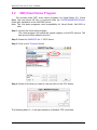
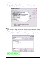
3.2
VB5 Client Demo Program
We provide three OPC client demo programs for Visual Basic 5.0, Visual
Basic .Net and Visual C# .Net. It is placed under the “\\ICPDAS\NAPOPC\Client\”
folder after installation of our NAPOPC server.
Note: The .Net demo programs could compatibility for Visual Studio .Net 2003 or
later.
Step 1: Launch the client demo program.
(The client program will search the system registry to find OPC servers. The
new servers will be added to the list. )
Step 2: Select the "NAPOPC.Svr.1" OPC Server.
Step 3: Click on the "Connect" button.
Step 4: Select a file which you want to use and click on the "OK" button.
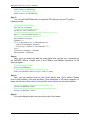
The following steps 5 ~ 6 are read operation of Modbus TCP controllers.
Ver: 3.09
Date: Oct-10-2008
Page: 42
NAPOPC DA Server User’s Manual
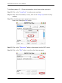
Step 5: Select a tag matching on your configuration.
(For example: Select the “i-8437" controller, "DO" group and "DO1" tag in the
tree-view window.)
Step 6: Click on the "Read" button to read the ““MTCP_8054.DO.DO1” value.
The following steps 7 ~ 9 are write operation of Modbus TCP controllers.
Step 7: Select a tag matching on your configuration.
(For example: Select the “i-8437" controller, "DO" group and "DO1" tag in the
tree-view window.)
Step 8: Fill in the "Tag-Value" field with 1.
Step 9: Click the "Write" button to write the “MTCP_8054.DO.DO1” value.
Ver: 3.09
Date: Oct-10-2008
Page: 43
NAPOPC DA Server User’s Manual
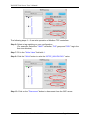
The following steps 10 ~ 12 are read operation, which loops unless you stop it.
Step 10: Click on the "Loop Read" to continuously read data.
Step 11: After about 5 seconds (or more), click on the "Stop Loop" button to stop
reading.
Step 12: A window pops up to show the performance.
Close it by clicking the "OK" button.
Step 13: Click on the "Disconnect" button to disconnect from the OPC server.
Step 14: Click on the "Exit" button to end the client demo program.
Ver: 3.09
Date: Oct-10-2008
Page: 44
NAPOPC DA Server User’s Manual
3.3
.Net Client Demo Program
We provide another two OPC client demo programs for Visual Basic .Net 2003
and Visual C# .Net 2003. It’s placed under the following folder
“\\ICPDAS\NAPOPC\Client\OPC_NetClientDemo\VBOPCClient_Demo” and
“\\ICPDAS\NAPOPC\Client\OPC_NetClientDemo\VCSOPCClient_Demo“after
installation of our NAPOPC server.
Step 1: Launch the client demo program “VBOPCClient_Demo.exe” or
“VCSOPCClient_Demo.exe”. (The client program set “NAPOPC.Svr.1” as
default OPC Server)
Step 2: Click on the "Connect" button.
Step 3: Select a file which you want to use and click on the "OK" button.
The following steps 4 ~ 5 are read operation of Modbus TCP controllers.
Step 4: Select a tag matching on your configuration.
(For example: Select the "i-8437" controller, "DO" group and "DO1" tag in the
tree-view window.)
Step 5: Click on the "Read" button to read the “MTCP_8054.DO.DO1” value.
Ver: 3.09
Date: Oct-10-2008
Page: 45
NAPOPC DA Server User’s Manual
The following steps 6 ~ 8 are write operation of Modbus TCP controllers.
Step 6: Select a tag matching on your configuration.
(For example: Select the "i-8437" controller, "DO" group and "DO1" tag in the
tree-view window.)
Step 7: Fill in the "Write Value" field with 1.
Step 8: Click the "Write" button to write the “MTCP_8054.DO.DO1” value.
Step 13: Click on the "Disconnect" button to disconnect from the OPC server.
Ver: 3.09
Date: Oct-10-2008
Page: 46
NAPOPC DA Server User’s Manual
3.4 FactorySoft's Client Program
Step 1: Click on the "OPC/ Connect…" menu item.
Step 2: Select the "NAPOPC.Svr.1 (NAPOPC DA Server)" OPC server.
Step 3: Click on the "OK" button.
Step 4: Select a file which you want to use and click on the "OK" button.
Step 5: Click on the "OPC/ Add Item" menu item to add existing tags.
Step 6: Browse the tree list. Then double-click on the tag to add.
Ver: 3.09
Date: Oct-10-2008
Page: 47
NAPOPC DA Server User’s Manual
Step 7: Click on the "Done" button to close.
Step 8: The window shows the values of selected tags.
Ver: 3.09
Date: Oct-10-2008
Page: 48
NAPOPC DA Server User’s Manual
3.5
LabVIEW
Step 1: Run the LabVIEW program and select “Open…” -> Example
Step 2: Click on the "Search Examples" button to get information on using OPC.
Step 3: Double-click on the "Multiple OPC Items Monitor.vi" item in the middle
window of NI Example Finder dialog..
Ver: 3.09
Date: Oct-10-2008
Page: 49
NAPOPC DA Server User’s Manual
Step 4: Click on the "Select Items" item in the "Multiple OPC Items Monitor.vi" demo.
Step 5: Run this demo.
Step 6: Click on a machine name in the "Network" tree-view.
Step 7: Select the "NAPOPC.Svr" OPC server.
Step 8: Click on the "OK" button to close it.
Step 9: Select a file which you want to use and click on the "OK" button.
Step 10: Select an item (tag) in the tree-view.
Ver: 3.09
Date: Oct-10-2008
Page: 50
NAPOPC DA Server User’s Manual
Step 11: Click on the "OK" button to add this one.
Step 12: Repeat the steps 6 ~ 11 to add more items(tags).
Step 13: Click on the "Cancel" button to finish adding items(tags).
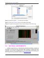
Step 14: The grid window graphs a line(s) to show changes of each item (tag).
3.6
NATIONAL INSTRUMENTS
National Instruments is a comprehensive industrial automation company by
providing the software, hardware, and technologies necessary to transform personal
computers into powerful computer-based and networked measurement and
automation systems. The ServerExplorer is one of their products for connecting to
OPC Server. For more information, please visit http://www.ni.com
Ver: 3.09
Date: Oct-10-2008
Page: 51
NAPOPC DA Server User’s Manual
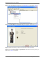
Step 1: Start ServerExplorer. Right-click on “NAPOPC.Svr”, then select “Wizard”.
Step 2: The OPC Wizard - Connection dialog box appears. Then click on “Next>”
Step 3: Select a file which you want to use and click on the "OK" button.
Step 4: Enter the Group Name and Update Rate. The name can be any name you
want. Click “Next>” to continue.
Ver: 3.09
Date: Oct-10-2008
Page: 52
NAPOPC DA Server User’s Manual
Step 5: Select all the items that you want to view from the Available OPC Items list.
Then click “Finish”.
Step 6: Now you should be able to view the OPC connection that you just created.
Ver: 3.09
Date: Oct-10-2008
Page: 53
NAPOPC DA Server User’s Manual
Step 7: To add new items, right-click on the group name then select “Add/Edit Items”.
Step 8: Make sure the Item ID textbox at the bottom has the correct object and item
name. Then click “Add>>” to add the item to the list on the right. In this example, we
add the “I7188EG_TCP.IO.V5”. Click “OK” when you are done.
Ver: 3.09
Date: Oct-10-2008
Page: 54
NAPOPC DA Server User’s Manual
Step 9: Now you should be able to read all the items that you added in the main
window.
Ver: 3.09
Date: Oct-10-2008
Page: 55
NAPOPC DA Server User’s Manual
3.7
WIZCON
Wizcon for Windows and Internet is a powerful HMI/SCADA software package
that delivers real-time and historical information from the plant floor to the boardroom
and beyond. For more information, please visit http://www.emation.com
Step 1: Run WIZCON (Version 7.51 or newer) program.
Step 2: Create a new project.
Step 3: Click on the "Communication Drivers" icon in the right hand window.
Ver: 3.09
Date: Oct-10-2008
Page: 56
NAPOPC DA Server User’s Manual
Step 4: Click on the "Add" button to add new drivers.
Step 5: Select the "OPC Client" item.
Step 6: Click on the "Next >" button.
Ver: 3.09
Date: Oct-10-2008
Page: 57
NAPOPC DA Server User’s Manual
Step 7: Enter the driver name (for example: "NAPOPC").
Step 8: Select the OPC Server Name as "NAPOPC.Svr.1".
Step 9: Click on the "Test Access" button to see if the OPC server can be accessed.
Step 10: Click on the "Finish" button.
Step 11: Click on the "Close" button.
Step 12: Click on the "OK" button to close the window.
Ver: 3.09
Date: Oct-10-2008
Page: 58
NAPOPC DA Server User’s Manual
Step 13: Click on the far-right icon (the arrow) to close the WIZCON.
Step 14: Restart the WIZCON.
Close
Step 15: Select the "Tags" item from the left-hand window.
Step 16: Right click the mouse button and select the "Add Tag" option to add tag(s).
Step 17: Enter a tag name in the "Tag Name" field.
Step 18: Select "PLC" in the "Tag Source" field.
Step 19: Select "NAPOPC"" in the "Driver" field.
Step 20: Select "Always" in the "Sample" field.
Step 21: Click on the "…" button to set the "Address" field.
Set Address
Ver: 3.09
Date: Oct-10-2008
Page: 59
NAPOPC DA Server User’s Manual
Step 22: Select a tag and click on the "OK" button.
Step 23: Click on the "OK" button to close it.
Step 24: The right hand window shows the tag(s) that were previously added.
Ver: 3.09
Date: Oct-10-2008
Page: 60
NAPOPC DA Server User’s Manual
Step 25: Click on the "Tools/ Multiple Tags" menu item.
Step 26: Click on the "OK" button to close the "Tag Filter" window.
Step 27: The "Tags Exerciser Program" window shows tag(s) and value(s).
Ver: 3.09
Date: Oct-10-2008
Page: 61
NAPOPC DA Server User’s Manual
3.8
iFix
iFIX is a powerful HMI/SCADA system that features full process visualization,
data collection and management, and supervisory control. iFIX, the HMI/SCADA
component of the Installation Dynamics family of automation software, is a Windows
NT-based industrial automation solution for monitoring and controlling manufacturing
operations. For more information, please visit http://www.intellution.com.
Step 1: Run iFix 2.1 and start system configuration.
Step 2: Click on the "Add" button to add I/O drivers.
Step 3: Select the "OPC - OLE for Process Control Client 7.12" driver.
Step 4: Click on the "OK" button.
Ver: 3.09
Date: Oct-10-2008
Page: 62
NAPOPC DA Server User’s Manual
Step 5: Select the "OPC - OLE for Process Control Client 7.12" driver.
Step 6: Click on the "Configure…" button to configure the I/O driver.
Step 7: Click on the "Connect…" button.
Ver: 3.09
Date: Oct-10-2008
Page: 63
NAPOPC DA Server User’s Manual
Step 8: To configure the OPC server.
Step 9: Select the "NAPOPC.Svr" and click on the "OK" button.
Ver: 3.09
Date: Oct-10-2008
Page: 64
NAPOPC DA Server User’s Manual
Step 10: Add server, group and items. Fill properties by clicking on the "Browse
Server…" button.
Step 11: Select the item which you need. Click on the "OK" button.
Ver: 3.09
Date: Oct-10-2008
Page: 65
NAPOPC DA Server User’s Manual
Step 12: Enter database manager of iFix 2.1.
Step 13: Add relative data units.
For example: AI.
Driver: "OPC OLE for Process Control Client 7.12".
I/O Address: "Server1;Group1:Item1".
Step 14: The window displays the current value of the AI unit.
Ver: 3.09
Date: Oct-10-2008
Page: 66
NAPOPC DA Server User’s Manual
3.9
InduSoft
InduSoft Web Studio is a powerful, integrated collection of automation tools that
includes all the building blocks needed to develop human machine interfaces (HMIs),
supervisory control and data acquisition (SCADA) systems, and embedded
instrumentation and control applications. Web Studio runs in native Windows NT,
2000, XP and CE 3.0 environments and conforms to industry standards such as
Microsoft DNA, OPC, DDE, ODBC, XML, SOAP and ActiveX. For more information
please visit: http://www.indusoft.com/
Step 1: Before using the InduSoft OPC Client module, you need to install and
configure the OPC server in the machines you will run it.
Ver: 3.09
Date: Oct-10-2008
Page: 67
NAPOPC DA Server User’s Manual
Step 2: Run the InduSoft (Version 4.1 or newer)
Step 3: Create the new project.
Ver: 3.09
Date: Oct-10-2008
Page: 68
NAPOPC DA Server User’s Manual
Step 4: In the Studio Workspace window, click the OPC tab, right-click the OPC
folder, and click “Insert”:
Step 5: OPC Attributes window pops up.
Ver: 3.09
Date: Oct-10-2008
Page: 69
NAPOPC DA Server User’s Manual
Step 6: Click on the Server Identifier: drop-down menu and select the
“NAPOPC.Svr”.
The configuration table for OPC has the following entries:
•
Description: this field is used for documentation only. The OPC Client module
ignores it.
•
Server Identifier: this field should contain the name of the server you want to
connect. If the server is installed in the computer, its name can be selected
through the list box.
•
Disable: this field should contain a tag or a constant. If its value is different of
zero, the communication with the OPC server is disabled.
•
Update Rate: this field indicates how often the server will update this group in
milliseconds. If it is zero indicates the server should use the fastest practical
rate.
•
Percent Deadband: this field indicates the percent change in an item value
that will cause a notification by the server. It's only valid for analog items.
•
Tag Name: these fields should contain the tags linked to the server items.
•
Item: these fields should contain the name of the server's items
Step 7: In the first cell of the Tag Name column type the tag name created in
database.
Step 8: In the first cell of the item you can right-click it to get a menu.
Ver: 3.09
Date: Oct-10-2008
Page: 70
NAPOPC DA Server User’s Manual
Step 9: Click the OPC Browser to appear the OPC Browser window.
Step 10: Select an item(tag) in the tree-view.
Step 11: Click the “OK” button to add this one.
Ver: 3.09
Date: Oct-10-2008
Page: 71
NAPOPC DA Server User’s Manual
Step 12: Repeat the step between 7 to 11 to add more tags.
Step 13: Creating a Text String for the Input/Output Dynamic. Click the Text icon on
the Object Editing toolbar. Position the crosshairs in the Display2.scr. Press the”#”
key three times to display “###” in the gray square.
Step 14: Click the Text Input/Output property icon on the Object Editing toolbar. Text
I/O appears in the drop-down menu of the Object Properties window. In the
Tag/Expression field type the tag name you want to link.
Ver: 3.09
Date: Oct-10-2008
Page: 72
NAPOPC DA Server User’s Manual
Step 15: From the Project select status. Then select the OPC Client Runtime in
“Execution Tasks” tab. Click on the Startup button to setup the Startup as Automatic.
Step 16: Run the program InduSoft OPC Client Runtime module automatically or by
the menu "Project->Status". After running this program, a small icon will appear in
your system tray. To close the InduSoft OPC Client module, right-click its icon in the
system tray, and select “Exit”.
Step 17: Database Spy allows you to monitor and forces application tags, reading
and writing to the database. You can find it in Tools menu.
Ver: 3.09
Date: Oct-10-2008
Page: 73
NAPOPC DA Server User’s Manual
3.10
Citect SCADA
CitectSCADA is a reliable, scaleable and high performance SCADA system
that includes over 100 drivers and free development software. Used in a wide range
of industries, CitectSCADA enables users to reduce costs by optimizing process
operations. Furthermore, it not only reduce risk with built-in redundancy for servers,
networks and communications, but open data connectivity via OPC client & server,
OLE DB, ODBC, DDE and API as well as over a hundred native drivers.
CitectSCADA can implement in Windows 98, NT and 2000. Visit
http://www.citect.com for more information about CitectSCADA
Step 1: Before using the CitectSCADA, you need to install and configure the OPC
server in the machines you will run it (see Chapter 1).
Step2: Start up the CitectSCADA with version 5.40.
Ver: 3.09
Date: Oct-10-2008
Page: 74
NAPOPC DA Server User’s Manual
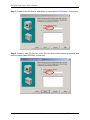
Step3: Left click the “page-marked button” or select “File / New Project…” from the
CitectSCADA window menu to build a new project in the CitectSCADA.
Step4: Fill a name of new project in the blank and then click “OK button” to finish this
process.
Ver: 3.09
Date: Oct-10-2008
Page: 75
NAPOPC DA Server User’s Manual
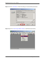
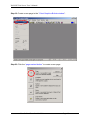
Step5: Click the “Express I/O Device Setup” icon to set all communication
parameters.
Step6: Start up the “Express Communications Wizard Dialog”.
Ver: 3.09
Date: Oct-10-2008
Page: 76
NAPOPC DA Server User’s Manual
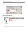
Step7: Create a new I/O Server and define a name called “OPCServer” for that one.
Step8: Create a new I/O Device under the I/O Server that created previously and
define a name called OPCDev for that one.
Ver: 3.09
Date: Oct-10-2008
Page: 77
NAPOPC DA Server User’s Manual
Step9: Select “External I/O Device” to be the type of OPCDev I/O Device.
Step10: Set OPC to be the method of communication for OPCDev I/O Device.
Ver: 3.09
Date: Oct-10-2008
Page: 78
NAPOPC DA Server User’s Manual
Step11: Set Address to be “NAPOPC.Svr.1” for OPCDev I/O Device.
Step12: Do not set any parameter in this step.
Ver: 3.09
Date: Oct-10-2008
Page: 79
NAPOPC DA Server User’s Manual
Step13: Click the “OK button” to finish the setting of communication parameters.
Step14: Open the “Citect Project Editor window” to edit Boards parameters.
Ver: 3.09
Date: Oct-10-2008
Page: 80
NAPOPC DA Server User’s Manual
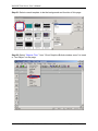
Step15: Edit Boards parameters. The Address (scanning period) is set to be
“250ms”, and the Special Opt is set to be blank.
Step16: Define two Variable Tags.
Ver: 3.09
Date: Oct-10-2008
Page: 81
NAPOPC DA Server User’s Manual
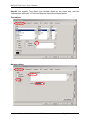
Step17: Define a variable tag for analog output of the modules 7021. The Variable
Tag Name is “A_out1”, the Data type is “REAL”, the I/O Device Name is selected to
be “OPCDev”, and the Address is “7021_1.AOs.Ch00”.(see Step 6 )
Step18: Define another variable tag for analog input of the modules 7012D. The
Variable Tag Name is “A_in1”, the Data type is “REAL”, the I/O Device Name is
selected to be “OPCDev”, and the Address is “7012D_2.AIs.Ch00”. (See Step 6 )
Ver: 3.09
Date: Oct-10-2008
Page: 82
NAPOPC DA Server User’s Manual
Step19: Create a new page in the “Citect Graphics Builder window”.
Step20: Click the “page-marked button” to create a new page.
Ver: 3.09
Date: Oct-10-2008
Page: 83
NAPOPC DA Server User’s Manual
Step21: Select normal template to be the background and function of this page.
Step22: Select “Objects /Text ” from “Citect Graphics Builder window menu” to insert
a “Text Object” on the page.
Ver: 3.09
Date: Oct-10-2008
Page: 84
NAPOPC DA Server User’s Manual
Step23: Key-in the words “AO:” in the Text object. Then, left click to put the Text
object on the page and set “Appearance parameters” of Text object.
Step24: Select “Objects/Number” from “Citect Graphics Builder window menu” to
insert a “Number Object” on the page. Left Click to put Number object on the page.
Then, set “Appearance attributes“ and “Input attributes” for this Number object.
Ver: 3.09
Date: Oct-10-2008
Page: 85
NAPOPC DA Server User’s Manual
Step25: Set another Text object and Number object by the same way, and the
“Appearance attributes” of Text and Number object are showed below.
Text object:
Number object:
Ver: 3.09
Date: Oct-10-2008
Page: 86
NAPOPC DA Server User’s Manual
Step26: When finish the all object and attribute setting, the page is looked like as
one, which shows below.
Step27: Select “File/Save ” from “Citect Graphics Builder window menu” to save this
page.
Ver: 3.09
Date: Oct-10-2008
Page: 87
NAPOPC DA Server User’s Manual
Step28: Fill the name of this page and save it under OPC_test project.
Step29: Left click the “computer-marked button” to define the role of this computer.
Ver: 3.09
Date: Oct-10-2008
Page: 88
NAPOPC DA Server User’s Manual
Step30: Start up the Citect Computer Setup Wizard.
Step31: Select the “Stand-alone computer” item to be the role of this computer.
Ver: 3.09
Date: Oct-10-2008
Page: 89
NAPOPC DA Server User’s Manual
Step32: Select the project “OPC_test” to be the project that this computer will run.
Step33: Click the “Next button” to next step.
Ver: 3.09
Date: Oct-10-2008
Page: 90
NAPOPC DA Server User’s Manual
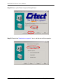
Step34: Left click the “Finish button” to finish the computer setup.
Step35: Select OPC_test project and press “F5” to run this project. Compare the
NAPOPC Server monitor and CitectSCADA runtime window.
Ver: 3.09
Date: Oct-10-2008
Page: 91
NAPOPC DA Server User’s Manual
Step36: Key-in the value “1.234” to output a voltage via the module 7021.
Step37: Both NAPOPC Server monitor and CitectSCADA runtime window show the
analog input of the modules 7012D is 1.231V.
Ver: 3.09
Date: Oct-10-2008
Page: 92
NAPOPC DA Server User’s Manual
Step38: Check if the analog output value of the modules 7021 that showed in the
NAPOPC Server monitor is 1.234V.
Ver: 3.09
Date: Oct-10-2008
Page: 93
NAPOPC DA Server User’s Manual
4
Remote Accessing
OPC Client has two ways to access the OPC Server. One is called “Local
Accessing”, and the other is called “Remote Accessing”. If the OPC Client and the
OPC Server are at the same computer, we said this kind of architecture is “Local
Accessing”. In other words, if the OPC Client should access OPC Server through a
network, we said this kind of architecture is “Remote Accessing”.
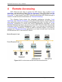
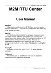
The following figure shows the integrated architecture including “Local
Accessing” and “Remote Accessing”. At the real Process Industry, the two ways are
often used at the same time. At the Process Management Layer, we often use “Local
Accessing” architecture to monitor and control manufacturing processes. At the
Business Management Layer, we just set up the OPC Client to collect the process
information from the Process Management Layer. If you just want to construct the
“Local Accessing” architecture, you do not need to read this chapter. If you want to
construct the “Remote Accessing” architecture, you have to know how to set up the
DCOM between OPC Client and OPC Server.
Figure 4-0-1 Local access and Remote access architecture.
Ver: 3.09
Date: Oct-10-2008
Page: 94
NAPOPC DA Server User’s Manual
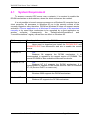
4.1
System Requirement
To access a remote OPC server over a network, it is required to enable the
DCOM mechanism on both stations, where the client and server are resided.
It is not possible to launch a secure process on a Windows 95 computer from a
client computer. All processes in Windows 95 run in the security context of the
currently logged-on user; therefore, DCOM on Windows 95 does not support remote
activation. A server application on a Windows 95 computer will have to be launched
manually or by some other mechanism to be accessed by a client application on
another
computer.
Consequently,
the
"DefaultLaunchPermissions"
and
"LaunchPermissions" registry values have no affect on Windows 95.
Platform
Windows 95
Does the platform support the DCOM?
No.
Users need to download and install the DCOM95.EXE and
DCM95CFG.EXE from Microsoft’s web site to enable the remote
access.
Windows 98
Yes.
Windows 98 supports the DCOM mechanism. It is
recommended to upgrade to the newest version of DCOM98. The
newest DCOM98 is also available at Microsoft’s web site.
Windows NT 4.0
Yes.
Windows NT 4.0 supports the DCOM mechanism. It is
recommended to upgrade to the newest Service Pack for Windows
NT 4.0 (Service Pack 3 or newer one).
Windows 2000
Yes.
Windows 2000 supports the DCOM mechanism.
Windows XP
Yes.
Windows XP supports the DCOM mechanism.
Ver: 3.09
Date: Oct-10-2008
Page: 95
NAPOPC DA Server User’s Manual
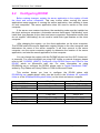
4.2
Configuring DCOM
Before making changes, register the server application in the registry of both
the client and server computers. This may involve either running the server
applications setup program or running the server application, then shutting it down
on both computers. The server application does not need to reside on the client
computer.
If the server uses custom interfaces, the marshaling code must be installed on
the client and server computers. Automation servers that support "vtbl-binding" must
install their type libraries on the client and server computers. Automation servers that
do not support "vtbl-binding" do not need to install their type libraries on the client
computer.
After changing the registry, run the client application on the client computer.
The DCOM looks at the server application registry entries on the client computer and
determines the name of the server computer. It will then connect to the server
computer, use the server computer registry to determine the location of the server
application, and start the server application on that computer.
You can change the registry with the DCOMCnfg.exe tool, the OLE Viewer tool,
or manually. For more information on using OLE Viewer or manual changes, please
refer to the “Q158582, HOWTO: Configure a Non-DCOM Server and Client to Use
DCOM” article on Microsoft’s web site. For more information on using
DCOMCnfg.exe to configure the DCOM, please refer to “Inside Distributed COM",
written by Guy Eddon and Henry Eddon in 1998 for Microsoft Press.
This section shows you how to configure the DCOM status with
DCOMCnfg.exe graphic-driven utility (can be found in the Windows NT system32
folder or in the Windows95/98 system folder) on the client and server computer.
Install NAPOPC Server
Platform
Configure DCOM
Client Site
Yes
Windows 98
Yes
Server Site
Yes
Windows NT 4.0 SP3
Yes
Install NAPOPC Server
Platform
Configure DCOM
Client Site
Yes
Windows XP
Yes
Server Site
Yes
Windows 2000
Yes
Ver: 3.09
Date: Oct-10-2008
Page: 96
NAPOPC DA Server User’s Manual
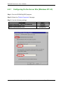
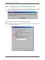
4.2.1
Configuring On the Server Site (Windows NT 4.0)
Step 1: Run the DCOMCnfg.EXE program.
Step 2: Select the "Default Properties" tab page.
Step 3: Use the following settings:
Field Name
Enable Distributed COM on this computer
Default Authentication Level:
Default Impersonation Level:
Ver: 3.09
Date: Oct-10-2008
Set to
Checked
Connect
Anonymous
Page: 97
NAPOPC DA Server User’s Manual
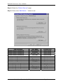
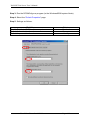
Step 4: Select the “Default Security” page.
Step 5: Click on the “Edit Default…” button to set.
Item to setting
Default Access Permissions
Default Access Permissions
Default Access Permissions
Default Access Permissions
User Name
Administrators
Everyone
INTERACTIVE
SYSTEM
Access Type
Allow Access
Allow Access
Allow Access
Allow Access
Default Launch Permissions
Default Launch Permissions
Default Launch Permissions
Default Launch Permissions
Administrators
Everyone
INTERACTIVE
SYSTEM
Allow Launch
Allow Launch
Allow Launch
Allow Launch
Default Configuration Permissions
Default Configuration Permissions
Default Configuration Permissions
Default Configuration Permissions
Administrators
Everyone
INTERACTIVE
SYSTEM
Full Control
Read
Full Control
Full Control
Ver: 3.09
Date: Oct-10-2008
Page: 98
NAPOPC DA Server User’s Manual
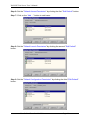
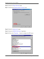
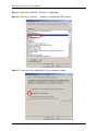
Step 6: Set the "Default Access Permission" by clicking the first "Edit Default" button.
Step 7: Click on the “Add …” button to add users.
Step 8: Set the "Default Launch Permission" by clicking the second "Edit Default"
button.
Step 9: Set the "Default Configuration Permission" by clicking the third "Edit Default"
button.
Ver: 3.09
Date: Oct-10-2008
Page: 99
NAPOPC DA Server User’s Manual
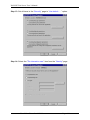
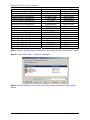
Step 10: Select the “NAPOPC DA Server” application.
Step 11: Click the “Properies…” button to configure the OPC server.
Step 12: Check the “Run application on this computer” option.
Ver: 3.09
Date: Oct-10-2008
Page: 100
NAPOPC DA Server User’s Manual
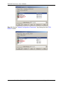
Step 13: Set all items in the “Security” page to “Use default…..” option.
Step 14: Select the “The interactive user” item from the "Identity" page.
Ver: 3.09
Date: Oct-10-2008
Page: 101
NAPOPC DA Server User’s Manual
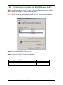
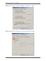
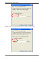
4.2.2
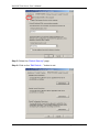
Configuring On the Client Site (Windows 98)
Run the DCOMCnfg.exe program. Users may get the following error message.
To avoid this message, configure the security to "User-level access control".
Step 1: Double click on the "Network" icon in the control panel.
Step 2: Configure the user's system with "User level access control" security in the
"Access Control" page.
Ver: 3.09
Date: Oct-10-2008
Page: 102
NAPOPC DA Server User’s Manual
Step 3: Run the DCOMCnfg.exe program (in the Windows95/98 system folder).
Step 4: Select the “Default Properties” page.
Step 5: Settings as follows:
Field Name
Enable Distributed COM on this computer
Default Authentication Level:
Default Impersonation Level:
Ver: 3.09
Date: Oct-10-2008
Set to
Checked
Connect
Identify
Page: 103
NAPOPC DA Server User’s Manual
Step 6: Select the "Default Security" page.
Step 7: Check on the "Enable remote connection" item.
Step 8: Select the "Applications" page.
Step 9: Select the "NAPOPC DA Server" application.
Step 10: Click on the "Properties…" button to configure the OPC server.
Ver: 3.09
Date: Oct-10-2008
Page: 104
NAPOPC DA Server User’s Manual
Step 11: Select the "Location" page.
Step 12: Settings as follows:
Field Name
Run application on the computer
where the data is located
Run application on this computer
Run application on the following computer
Set to
Unchecked
Unchecked
Checked
and key in the OPC server's
computer name or IP address.
Step 13: Check the "Run application on the following computer:" option.
Step 14: Key in the IP address of the OPC server.
Ver: 3.09
Date: Oct-10-2008
Page: 105
NAPOPC DA Server User’s Manual
Step 15: Users can also key in the OPC server's computer name in the field.
Step 16: Select the "Security" page.
Step 17: Select the "Use default access permissions" option.
Ver: 3.09
Date: Oct-10-2008
Page: 106
NAPOPC DA Server User’s Manual
4.2.3
Configuring On the Server Site (Windows 2000)
Step 1: Create a new user “test1” by using “Users and Passwords” in the Control
Panel, and set its Group as “Power Users” as follow.
NOTE: On the client site, remember to create the “test1” account which has the
same “Username” and “Passwaord” with one on the server site.
Step 2: Run the DCOMCnfg.EXE program.
Step 3: Select the "Default Properties" tab page.
Step 4: Use the following settings:
Field Name
Enable Distributed COM on this computer
Default Authentication Level:
Default Impersonation Level:
Ver: 3.09
Date: Oct-10-2008
Set to
Checked
Connect
Anonymous
Page: 107
NAPOPC DA Server User’s Manual
Step 5: Select the “Default Security” page.
Step 6: Click on the “Edit Default…” button to set.
Ver: 3.09
Date: Oct-10-2008
Page: 108
NAPOPC DA Server User’s Manual
Item to setting
Default Access Permissions
Default Access Permissions
Default Access Permissions
Default Access Permissions
Default Access Permissions
User Name
Administrators
Everyone
INTERACTIVE
Power Users
SYSTEM
Access Type
Allow Access
Allow Access
Allow Access
Allow Access
Allow Access
Default Launch Permissions
Default Launch Permissions
Default Launch Permissions
Default Launch Permissions
Default Launch Permissions
Administrators
Everyone
INTERACTIVE
Power Users
SYSTEM
Allow Launch
Allow Launch
Allow Launch
Allow Launch
Allow Launch
Administrators
CREATOR OWNER
Everyone
Power Users
SYSTEM
Users
Full Control
Full Control
Read
Full Control
Full Control
Full Control
Default Configuration Permissions
Default Configuration Permissions
Default Configuration Permissions
Default Configuration Permissions
Default Configuration Permissions
Default Configuration Permissions
Step 7: Set the "Default Access Permission" by clicking the first "Edit Default" button.
Step 8: Click on the “Add …” button to add users.
Step 9: Set the "Default Launch Permission" by clicking the second "Edit Default"
button.
Ver: 3.09
Date: Oct-10-2008
Page: 109
NAPOPC DA Server User’s Manual
Step 10: Set the "Default Configuration Permission" by clicking the third "Edit
Default" button.
Ver: 3.09
Date: Oct-10-2008
Page: 110
NAPOPC DA Server User’s Manual
Step 11: Select the “NAPOPC DA Server” application.
Step 12: Click the “Properies…” button to configure the OPC server.
Step 13: Check the “Run application on this computer” option.
Ver: 3.09
Date: Oct-10-2008
Page: 111
NAPOPC DA Server User’s Manual
Step 14: Set all items in the “Security” page to “Use default…..” option.
Step 15: Select the “The interactive user” item from the "Identity" page.
Ver: 3.09
Date: Oct-10-2008
Page: 112
NAPOPC DA Server User’s Manual
4.2.4
Configuring On the Client Site (Windows XP)
Step 1: Log in with “test1” account.
NOTE: On the server site, remember to create the “test1” account which has the
same “Username” and “Passwaord” with one on the client site.
Step 2: Run the DCOMCnfg.EXE program.
Step 3: Select the "NAPOPC DA Server" and righ-click on it. You will see
“Properties” and click on it.
Ver: 3.09
Date: Oct-10-2008
Page: 113
NAPOPC DA Server User’s Manual
Step 4: Select the “General” page and set the “Default” in the “Authentication Level”
field.
Step 5: Select the "Location" page.
Step 6: Settings as follows:
Field Name
Run application on the computer
where the data is located
Run application on this computer
Run application on the following computer
Set to
Unchecked
Unchecked
Checked
and key in the OPC server's
computer name or IP address.
Step 7: Check the "Run application on the following computer:" option.
Step 8: Key in the IP address of the OPC server.
Ver: 3.09
Date: Oct-10-2008
Page: 114
NAPOPC DA Server User’s Manual
Step 9: Users can also key in the OPC server's computer name in the field.
Ver: 3.09
Date: Oct-10-2008
Page: 115
NAPOPC DA Server User’s Manual
Step 10: Select the "Security" page.
Step 11: Set all items in the “Security” page to “Use Default” option.
Step 12: Select the “The interactive user” item in the "Identity" page.
Ver: 3.09
Date: Oct-10-2008
Page: 116
NAPOPC DA Server User’s Manual
5
Writing Client Program with VB
5.1
Programming with VB5
5.1.1
Overview of OPC & VB
Visual Basic language supports COM(Component Object Model). COM
implementation from Visual Basic use what is called an “Automation” interface. The
OPC Foundation supplies the source code of “Automation Wrapper” DLL which lets
VB access OPC Servers and their underlying Groups and items. That’s why we have
to install the OPC DAC (Data Access Component.) software(see 2 Quick Start). After
we install the OPC DAC software, we can use Automation Wrapper connects VB to
OPC.
The following figure shows the architecture of object model for the automation
wrapper. Because the OPC Server Object contains Group Objects and Items
Objects by using Collection, OPC Browse Object can access the item data through
the pointer of OPC Server Object.
OPC Server Object
OPC Groups Collection
OPC Browse Object
OPC Group Objects
OPC Items Collection
OPC Items Objects
Figure 5-1-1. Object model for the Automation Wrapper
The following figure shows the architecture of OPC Server Object through the
Automation Wrapper under COM/DCOM mechanism. The VB program wakes up the
remote OPC Server Object through the automation wrapper object by DCOM
mechanism.
Ver: 3.09
Date: Oct-10-2008
Page: 117
NAPOPC DA Server User’s Manual
Your VB Program
with the Automation
Wrapper object
included in it
OPC Server Object
OPC Groups Collection
OPC Browse Object
OPC Group Objects
OPC Items Collection
The Automation Wrapper
connects to the OPC server
and creates the groups and
items in the server and gives
you references to them in
your VB program in an
Object model that mirrors
that of the server
OPC Items Objects
COM/DCOM
OPC Server Object
OPC Groups Collection
Your OPC Server
and it’s object model
OPC Group Objects
OPC Items Collection
OPC Items Objects
Figure 5-1-2. Architecture of OPC Server Object under COM/DCOM mechanism
5.1.2
Tools You Will Need to Build Your VB Client
If you want to build an OPC client in VB and test it, you will need the following
tools.
Visual Basic 5 or 6 running on Windows 95/98/2000/ME/NT/XP
An OPC Server
At this manual, we use ICPDAS NAPOPC Server as the demo. You can find
it at your CD:\\Napdos\Napopcsvr\ or you can download it from the
http://www.icpdas.com/download/7000/napopcsvr.htm
The OPC Automation Wrapper
You can find it from http://www.icpdas.com/download/7000/napopcsvr.htm
5.1.3
Building Your VB Client – Step By Step
At this section, we just focus on the key steps of building the VB client. If you
want to know more information about OPC Automation 2.0 and the VB demo, please
refer to the opcda20_auto.pdf in the C:\ICPDAS\NAPOPC\Manual and the VB demo
source code in the C:\ICPDAS\NAPOPC\Client\VB5.
Step 1:
Install OPCDAC on your PC
Start a new VB project
Ver: 3.09
Date: Oct-10-2008
Page: 118
NAPOPC DA Server User’s Manual
In VB, click on Project -> References on the VB menu bar
The OPC Automation Wrapper appears on the dialog as “OPC Automation
2.0” – select it as shown here
Step 2:
First, you have to design your UI(User Interface). You can refer to the UI demo
of VB program shown as below. Next, you need to declare some variables at the
General Declarations area of VB code window. The most important types of
variables are OPCServer, OPCGroup, and OPCBrowser. As the declaration, we can
use several functions to read/write item values through Server and Group variables.
'Declare a new OPC Server object
Public Server As OPCServer
‘Declare a new OPC Group object
Ver: 3.09
Date: Oct-10-2008
Page: 119
NAPOPC DA Server User’s Manual
Public Group As OPCGroup
‘Declare a new Browser object
Public browser As OPCBrowser
Step 3:
You can call GetOPCServers() to scan the OPC Servers at your PC as the
following codes.
'Declare a Variant Variable
Dim Servers As Variant
'Create a new OPC Server object
Set Server = New OPCServer
'Call GetOPCServers to scan the OPC Servers on your PC
Servers = Server.GetOPCServers("")
'Show the servers on the Combo box
Dim lastIndex As Integer
lastIndex = 0
For I = LBound(Servers) To UBound(Servers)
cbServerList.AddItem Servers(I)
If Servers(I) = lastServer Then lastIndex = I - 1
Next I
cbServerList.ListIndex = lastIndex
MousePointer = vbDefault
Step 4:
Next, you’ll go ahead and add the code rights after you get your connection to
the NAPOPC Server. Please refer to the FillItems and Branch subroutine of VB
demo program.
'Generate the tree of tags
Private Sub FillItems()
'Populate the sub branches in the browser tree
Public Sub Branch(Count As Integer, node1 As node)
Step 5:
Now, you can add the code for the “Read” button and “Write” button. Please
refer to the btnRead_Click and btnWrite_Click subroutine of VB demo program. In
these two functions, the anItem.Read and the anItem.Write are two key methods.
'Read the OPCItem value after the read button press
Private Sub btnRead_Click()
'Write the value in the text box after the write button press
Private Sub btnWrite_Click()
Step 6:
You can build the project and you will see the UI as below.
Ver: 3.09
Date: Oct-10-2008
Page: 120
NAPOPC DA Server User’s Manual
Step 7:
After you click on the “Connect” button, you will see the OPC Server tree list.
You can choose one of them and click on the “Read” button. You will see the item
value at the “Tag Value” field as below. You can also type the value you want to
write in the text box and click on the “Write” button. (Refer to 4.1 Client Demo
Program)
5.2
5.2.1
Programming with .Net
Limitations about .Net client programming
1. OPC DA component 2.0 must be installed. (In this case, OPC DA Component 1.0
can’t be used)
Ver: 3.09
Date: Oct-10-2008
Page: 121
NAPOPC DA Server User’s Manual
2. Development was done on a Windows XP SP1 system using Microsoft
Development Environment 2003 version 7.1.3091 with .Net Framework 1.1
version 1.1.4322 and any new release version of .Net will need to modify these
codes.
3. Testing was done on following operation system, any others might not work
- Windows 98 second edition 4.10.2222A
- Windows 2000 professional 5.00.2195 service pack 4
- Windows XP professional version 2002 service pack 1
5.2.2
Tools – You Need to Build Your .Net Client
If you want to build an OPC VB .Net or VC# client and test it, you will need
following tools.
Visual Basic .Net 2003 or newer version running on Windows 98/2000/XP
OPC Automation 2.0
You can find it at your CD:\\Napdos\napopcsvr\OPCDAC or download it
from http://www.icpdas.com/download/7000/napopcsvr.htm
An OPC Server
At this manual, we use ICPDAS NAPOPC Server as the demo. You can find
it at your CD:\\Napdos\napopcsvr\ or download it from the
http://www.icpdas.com/download/7000/napopcsvr.htm
OPC .Net wrapper named “OPCNetWrapper.dll”.
You can find it at your CD:\\Napdos\napopcsvr or download it from
http://www.icpdas.com/download/7000/napopcsvr.htm
5.2.3
Building Your VB.Net Client – Step By Step
Step 1:
Install OPC DA Component 2.0 on your PC
Start a new VB.Net project with “Windows Application Program”
In VB.Net, click Project -> Add References on the VB.Net menu bar
Click Browse… to select “OPCNetWrapper.dll” as shown below
Ver: 3.09
Date: Oct-10-2008
Page: 122
NAPOPC DA Server User’s Manual
Step 2:
First, you must Import following declarations “ICPDAS.OPC”,”ICPDAS.OPCDA”
and “ICPDAS.OPC.NET”. Second, you could design your UI (User Interface). You
can refer to the UI of VB.Net program shown as below. Third, you need to declare
some variables at the General Declarations area of VB.Net code window. The most
important types of variables are ICPDAS_OPCServer, ICPDAS_SyncIOGroup, and
ServerTreeBrowser. As the declaration, we can use several functions to read/write
tag values through Server and Group variables.
'Declare a new ICPDAS_OPCServer object
Dim Svr As ICPDAS_OPCServer
‘Declare two new ICPDAS_SyncIOGroup objects
Dim ReadWriteGroup, Grp As ICPDAS_SyncIOGroup
‘Declare a new ServerTreeBrowser object
Ver: 3.09
Date: Oct-10-2008
Page: 123
NAPOPC DA Server User’s Manual
Dim TagTree As ServerTreeBrowser
'Declare two new RefreshGroup objects
Dim AsyncRefrGroup, rGrp As RefreshGroup
‘Declare a new TagDef object
Dim TagData As TagDef
‘Declare a new String variable for OPC Server ProgID
Dim ServerName As String
Step 3:
You can set ServerName as “NAPOPC.Svr.1” and pass it to
ICPDAS_OPCServer for connecting.
'Set a ProgID to ServerName
ServerName = "NAPOPC.Svr.1"
'Create a new OPC Server object
Svr = New ICPDAS_OPCServerr
'Connect to NAPOPC DA Server
Svr.Connect (ServerName)
Step 4:
Now, you’ll go ahead and add the code rights after you get your connection to
the NAPOPC Server. Please refer to following TagReadWrite and DataChangeHandler
subroutine of VB demo program.
‘Handles of data change callbacks
Public Sub DataChangeHandler (ByVal sender As Object, ByVal e As
DataChangeEventArgs)
Private Sub TagReadWrite (ByVal lgrp As ICPDAS_SyncIOGroup, ByVal lrgrp As
RefreshGroup, ByVal iTree As ServerTreeBrowser, ByVal tagId As String)
Step 5:
Now, you can add codes for the “Read” button, “Write” button and “TreeView”
AfterSelect function. Please refer to the btnRead_Click, btnWrite_Click and
tvTags_AfterSelect subroutine of VB.Net demo program. In these three functions,
the Grp.Read, the Grp.Write and the TagTree.TagName are three key methods.
'Read the OPCTag value after the read button press
Private Sub btnRead_Click ()
'Write the value in the text box after the write button press
Private Sub btnWrite_Click ()
‘The action after selecting the tag
Private Sub tvTags_AfterSelect ()
Step 6:
You can build the project and you will see the UI as below.
Ver: 3.09
Date: Oct-10-2008
Page: 124
NAPOPC DA Server User’s Manual
Step 7:
After you click on the “Connect” button, you will see the OPC Server tree list.
You can choose one of them and click on the “Read” button. You will see the tag
value at the “Read Value” field as below. You can also type the value you want to
write in the “Write Value” and click on the “Write” button. (Refer to 4.2 .Net Client
Demo Program)
Ver: 3.09
Date: Oct-10-2008
Page: 125
NAPOPC DA Server User’s Manual
5.2.4
Step 1:
Building Your VC#.Net Client – Step By Step
Install OPC DA Component 2.0 on your PC
Start a new VC#.Net project with “Windows Application Program”
In VC#.Net, click Project -> Add References on the VC#.Net menu bar
Click Browse… to select “OPCNetWrapper.dll” as shown below
Step 2:
First, you must using directive as following declarations:
“ICPDAS.OPC”,”ICPDAS.OPCDA” and “ICPDAS.OPC.NET”. Second, you could
design your UI (User Interface). You can refer to the UI of VC#.Net program shown
as below. Third, you need to declare some variables at the General Declarations
area of VC#.Net code window. The most important types of variables are
ICPDAS_OPCServer, ICPDAS_SyncIOGroup, and ServerTreeBrowser. As the
declaration, we can use several functions to read/write tag values through Server
and Group variables.
Ver: 3.09
Date: Oct-10-2008
Page: 126
NAPOPC DA Server User’s Manual
'Declare a new ICPDAS_OPCServer object
ICPDAS_OPCServer
Svr = null;
‘Declare two new ICPDAS_SyncIOGroup objects
ICPDAS_SyncIOGroup
ReadWriteGroup, Grp;
‘Declare a new ServerTreeBrowser object
ServerTreeBrowser
TagTree;
'Declare two new RefreshGroup objects
RefreshGroup
AsyncRefrGroup, rGrp;
‘Declare a new TagDef object
TagDef
TagData;
‘Declare a new String variable for OPC Server ProgID
string
ServerName;
Step 3:
You can set ServerName as “NAPOPC.Svr.1” and pass it to
ICPDAS_OPCServer for connecting.
'Set a ProgID to ServerName
ServerName = "NAPOPC.Svr.1;"
'Create a new OPC Server object
Svr = new ICPDAS_OPCServer ();
'Connect to NAPOPC DA Server
Svr.Connect (ServerName);
Step 4:
Now, you’ll go ahead and add the code rights after you get your connection to
the NAPOPC Server. Please refer to following TagReadWrite and DataChangeHandler
subroutine of VC# demo program.
‘Handles of data change callbacks
public void DataChangeHandler ( object sender, DataChangeEventArgs e )
public void TagReadWrite ( ICPDAS_SyncIOGroup grp, RefreshGroup rgrp,
ServerTreeBrowser iTree, string tagId)
Step 5:
Now, you can add codes for the “Read” button, “Write” button and “TreeView”
AfterSelect function. Please refer to the btnRead_Click, btnWrite_Click and
tvTags_AfterSelect subroutine of VC#.Net demo program. In these three functions,
the Grp.Read, the Grp.Write and the TagTree.TagName are three key methods.
'Read the OPCTag value after the read button press
private void btnRead_Click (object sender, System.EventArgs e)
'Write the value in the text box after the write button press
private void btnWrite_Click(object sender, System.EventArgs e)
‘The action after selecting the tag
private void tvTags_AfterSelect(object sender,
System.Windows.Forms.TreeViewEventArgs e)
Ver: 3.09
Date: Oct-10-2008
Page: 127
NAPOPC DA Server User’s Manual
Step 6:
You can build the project and you will see the UI as below.
Step 7:
After you click on the “Connect” button, you will see the OPC Server tree list.
You can choose one of them and click on the “Read” button. You will see the tag
value at the “Read Value” field as below. You can also type the value you want to
write in the “Write Value” field and click on the “Write” button. (Refer to 4.2 .Net
Client Demo Program)
Ver: 3.09
Date: Oct-10-2008
Page: 128
NAPOPC DA Server User’s Manual
6
NAPOPC Changes List
6.1
New features of NAPOPC version 3.0
The new features of NAPOPC version 3.0 are briefly described in this chapter.
6.1.1
New IO Kernel
NAPOPC version 3.0 uses new IO kernel “IOCtrl.DLL” and
“DCON_PC.DLL” to elevate IO communication performance. Also, the new IO kernel
architecture allows customers only to update “module.ini” for getting new module
support.
6.1.2
Customized Module/Device Polling Time
NAPOPC version 3.0 allows customers to optimize their communication by
setting “Pending Time” in “Device Dialog “. Customers have chance to spread more
time resource to other modules which are connected with each other. Please refer to
“3.1 Optimize Your Communication” in detail.
6.1.3
Multi-Thread Communication
NAPOPC version 3.0 uses multi-thread architecture to organize module
and device communication. Before NAPOPC version 3.0, NAPOPC uses singlethread to deal with module and device communication. Therefore, if NAPOPC
connects many modules and devices, accessing time will increase observably. By
NAPOPC version 3.0, customers have chances to group modules and devices into
several parts, and connect via different COM port. One COM port works in one
thread. All TCP communications belong to one thread.
Here is an example to show the difference of average scan time between
NAPOPC version 3.0 and before NAPOPC version 3.0.
Under the same architecture, the average scan time in NAPOPC version
3.0 is 375 ms and 539 ms separately. Before NAPOPC version 3.0, the average
scan time is 1109 ms.
Ver: 3.09
Date: Oct-10-2008
Page: 129
NAPOPC DA Server User’s Manual
6.1.4
Miscellaneous
z
z
6.2
6.2.1
Remove “import/export CSV file” function
Remove “debug logging” function
New features of NAPOPC version 3.09
Support Remote Procedure Call with Quicker/UPC
NAPOPC version 3.09 supports RPC(Remote Procedure Call) communication
with Quicker and UPC(ICP DAS Universal Protocol Converter). Based on RPC
service, NAPOPC can synchronize OLE data with Quicker and UPC automatically.
The behavior of changing data between “Quicker/UPC” and NAPOPC is not polling
from NAPOPC but sending from “Quicker/UPC”. This mechanism can transfer data
effectively and shorten response time.
6.2.2
Switch of Single-Thread and Multi-Thread
NAPOPC version 3.09 supports “Communication Mechanism” option at
"Options/ Configurate Initial Status". This option lets user define the communication
behavior of NAPOPC. Generally, “Multi-Thread” is the best choice for high
performace. However, for some particular OPC clients which can not work smoothly
under “Multi-Thread” communication, user can choose “Single-Thread” instead.
Ver: 3.09
Date: Oct-10-2008
Page: 130
NAPOPC DA Server User’s Manual
7
Reference
FAQ.txt
The frequently asked questions and answers.
Modules.htm
A list of modules the NAPOPC DA Server supports.
A list of module-supported commands.
Descriptions of each command type.
GetStart.PDF
This manual can be downloaded from below link.
http://www.icpdas.com/download/7000/manual.htm
It describes the following topics:
1. Connecting modules
2. The 7000 Utility user's manual.
3. Introduction to NAP7000P
4. Introduction to NAP7000X
5. Dual Watchdog
6. FAQ for 7000
OPCOvw.PDF
The OPC overview - written by the OPC Foundation.
OPCCommn.PDF
The OPC common interface - specifications by the OPC Foundation.
OPCDA20_Cust.PDF
The OPC DA v2.0 custom interface - specifications by the OPC Foundation.
OPCDA20_Auto.PDF
The OPC DA v2.0 automation interface - specifications by the OPC
Foundation.
OPC Foundation Web Site
http://www.opcfoundation.org/
Ver: 3.09
Date: Oct-10-2008
Page: 131