1
4/8/16-CH DVR CD-RW
PDR-6040/6080/6160 A/S
MERIT LILIN ENT. CO., LTD
http://www.meritlilin.com
66-6160CSE
INSTRUCTION MANUAL
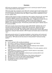
Summary
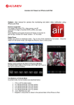
Merit LILIN 6 series MPEG-4 DVRs are designed to meet the demands for complete range of
DVRs including 4-channel, 8-channel, and 16-channel in one system platform. Adopting same
system platform, it gives flexibility and capability for users in expending systems for future
without considering compatibility. Merit LILIN 6 series MPEG-4 DVRs adopt high compression
rate MPEG-4 engine for video streaming. The combination uses of Group of Pictures (GOP)
and Noise Reduction Filter (NRF) at night maximize storage utilization.
Storage system of the DVRs can be extended by using cost-effective Merit LILIN PSH-100
RAID system to gain up to 4 TB in size. SATA interface provides faster HDD access speed
and prevents mechanical failure caused by 40-pin IDE connector. Video data file recovery and
monitoring technologies secure the data file from power failure.
Various backup plans
including DVD/RW drive, USB flash disk, and FTP file download allow the user to operate file
backup task anywhere.
Web interface provides network connectivity via Internet browser. Complete DVR features
including remote file backup configurable from the web interface, there is no need for on-site
maintenance. Free central management system (CMX) allows to digitally manage DVRs in
control centers remotely. By simple mouse click, operator can gain live video worldwide.
Plug-n-play RJ-45 3D joystick keyboard support, cascading camera name, easy-to-setup
DVRs daisy chain connection via RJ-45, addressable DVR ID, and IR receiver extension
provide the easiest way in setup a large-scare DVR systems.
Powerful MPEG-4 compression technology, complete storage and backup plans, full digital
and analog system solutions, easy-to-use user interface, and full range accessories support,
the new Merit LILIN 6 series MPEG-4 standalone digital video recorder is the only choice for
surveillance system.
Major Features
MPEG-4 compression engine
Built-in VGA with intellectual motion adoptive refinement and vivid image enhancement
HTTP web-based interface including DVR configuration, PTZ control, playback, and live
monitoring
Up to 480(NTSC)/400(PAL) frames per second in live
Frame rate and video quality configurable each channel
Extra spot output with quad and OSD support
4-channel audio inputs and 1 audio output
Network audio & backup audio supports
SATA HDD support with external e-SATA connector for maximum 4TB recording capability
Portable USB 2.0 flash disk, DVD/RW, or FTP backup with AVI or MPEG-4
Easy-to-use jog, shuttle, mouse, and 3D joystick
Daylight saving time (DST)
Trademarks and registered trademarks
Microsoft, Windows 2000, Windows XP, Internet Explorer are registered trademarks of
Microsoft Corporation in the U.S. and/or other countries.
Windows Media Player is registered trademarks of Microsoft Corporation in the U.S. and/or
other countries.
Adobe and Adobe PDF are registered trademarks of Adobe Systems Incorporated in the U.S.
and/or other countries.
JavaScript and all Java-based trademarks and logos are trademarks or registered trademarks
of Sun Microsystems, Inc. in the U.S. and/or other countries.
Linux, Macintosh, Mozilla, Netscape Navigator, are registered trademarks of the respective
holders.
Pelco is a trademark of Pelco - Clovis, CA, and may be registered in certain jurisdictions.
Other names of companies and their products mentioned in this manual may be trademarks or
registered trademarks of their respective owners.
Caution
•
Do not drop or strike this equipment
•
Do not install the equipment near any naked flames or heat sources
•
Do not expose this unit to rain, moisture, smoke or dust environment
•
Do not cover the opening of the cabinet with cloth and plastic or to install this unit
in poor ventilated places. Allow 10cm between this unit and its surroundings
•
Do not continue to operate the unit under abnormal conditions such as detection
of smoke, strange smell or no display on screen while power is turned on
•
Do not touch the power connection with wet hands
•
Do not damage the power cord or leave it under pressure
•
Do not operate this unit near magnet, speaker system, etc., to avoid unnecessary
magnetic interference
•
Connection cables should be grounded properly
CAUTION
RISK OF EXPLOSION IF BATTERY IS REPLACED
BY AN INCORRECT TYPE.
DISPOSE OF USED BATTERIES ACCORDING
TO THE INSTRUCTIONS
PDR-6160/PDR-6080/PDR-6040 User Manual
1
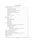
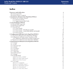
TABLE OF CONTENTS
CHAPTER 1. SYSTEMS OVERVIEW ...................................................................................... 6
Chapter 1-1. Front Panel.................................................................................................... 6
Chapter 1-2. Rear View...................................................................................................... 8
Chapter 1-3. System LED Status Panel............................................................................. 9
Chapter 1-4. Remote controller........................................................................................ 10
Chapter 1-5. Jog & Shuttle................................................................................................11
Chapter 1-6. Mouse System .............................................................................................11
Chapter 1-6-1. Mouse Menu...................................................................................... 12
Chapter 1-7. Active Camera............................................................................................. 12
CHAPTER 2. DVR OPERATIONS ......................................................................................... 14
Chapter 2-1. Sequential Display ...................................................................................... 14
Chapter 2-2. Freeze ......................................................................................................... 14
Chapter 2-3. Zoom ........................................................................................................... 14
Chapter 2-4. CH+ & CH- .................................................................................................. 15
Chapter 2-5. Audio & Mute............................................................................................... 15
Chapter 2-6. Addressable DVR Control Button................................................................ 15
Chapter 2-7. NTSC/PAL................................................................................................... 15
Chapter 2-8. Language .................................................................................................... 15
Chapter 2-9. ESC/Shutdown Procedure .......................................................................... 15
Chapter 2-10. OK/Cancel Button ..................................................................................... 15
CHAPTER 3. PTZ CONTROL ................................................................................................ 16
Chapter 3-1. Instant PTZ Controllable Mode ................................................................... 16
Chapter 3-2. Remote Controller & PTZ............................................................................ 16
Chapter 3-3. Recall Presets ............................................................................................. 16
CHAPTER 4. RECORDING ................................................................................................... 17
Chapter 4-1. Start Recording ........................................................................................... 17
Chapter 4-2. Manual Recording ....................................................................................... 17
Chapter 4-3. Schedule Recording.................................................................................... 17
Chapter 4-4. Alarm Switch Activation Recording ............................................................. 17
Chapter 4-5. Motion Detection Recording........................................................................ 17
CHAPTER 5. PLAYBACK....................................................................................................... 18
Chapter 5-1. Time Search ................................................................................................ 18
Chapter 5-2. Event Search............................................................................................... 18
Chapter 5-3. REC Search ................................................................................................ 19
Chapter 5-4. Other Playback Features ............................................................................ 19
CHAPTER 6. MENU SYSTEM ............................................................................................... 21
Chapter 6-1. Setup Menu................................................................................................. 21
Chapter 6-2. Camera Setup ............................................................................................. 21
PDR-6160/PDR-6080/PDR-6040 User Manual
2
Chapter 6-2-1. Camera Name ................................................................................... 21
Chapter 6-2-2. Channel Enable................................................................................. 22
Chapter 6-2-3. Video Setup....................................................................................... 22
Chapter 6-2-4. Sequence Time ................................................................................. 24
Chapter 6-3. Monitor Setup.............................................................................................. 23
Chapter 6-3-1. Main Alarm Switching ......................................................................... 24
Chapter 6-3-2. SPOT/QUAD Sequence ..................................................................... 24
Chapter 6-4. Record Setup .............................................................................................. 25
Chapter 6-4-1. Record Quality................................................................................... 25
Chapter 6-4-2. Frame Rate ....................................................................................... 25
Chapter 6-4-3. Recording Mode ................................................................................ 25
Chapter 6-4-4. Audio ................................................................................................. 25
Chapter 6-4-5. Pre-alarm Recording ......................................................................... 26
Chapter 6-4-6. Post-alarm Recording ....................................................................... 26
Chapter 6-4-7. Resolution ......................................................................................... 26
Chapter 6-4-8. GOP .................................................................................................. 26
Chapter 6-4-9. Schedule ........................................................................................... 26
Chapter 6-4-10. HDD Overwritten ............................................................................. 27
Chapter 6-4-11. Limited Recording............................................................................ 27
Chapter 6-5. Alarm Setup................................................................................................. 27
Chapter 6-5-1. Alarm Input Type ............................................................................... 27
Chapter 6-5-2. Motion Enable ................................................................................... 27
Chapter 6-5-3. Sensitivity .......................................................................................... 27
Chapter 6-5-4. Motion Area Set................................................................................. 28
Chapter 6-5-5. Motion Tracer .................................................................................... 28
Chapter 6-5-6. Alarm Time ........................................................................................ 28
Chapter 6-5-7. Buzzer Enable ................................................................................... 28
Chapter 6-5-8. Button Sound..................................................................................... 28
Chapter 6-6. System Setup.............................................................................................. 29
Chapter 6-6-1. Date/Time .......................................................................................... 29
Chapter 6-6-2. HDD Information................................................................................ 30
Chapter 6-6-3. Password/Access .............................................................................. 30
Chapter 6-6-4. LOG View .......................................................................................... 31
Chapter 6-6-5. Factory Reset .................................................................................... 32
Chapter 6-6-6. DVR/RS-485 ID ................................................................................. 32
Chapter 6-6-7. Video System .................................................................................... 32
Chapter 6-6-8. Firmware Update............................................................................... 32
Chapter 6-6-9. Language .......................................................................................... 33
Chapter 6-6-10. Live Audio........................................................................................ 33
PDR-6160/PDR-6080/PDR-6040 User Manual
3
Chapter 6-7. Network ....................................................................................................... 34
Chapter 6-7-1. Port Number ...................................................................................... 34
Chapter 6-7-2. DDNS ................................................................................................ 34
Chapter 6-8. PTZ Setup ................................................................................................... 34
Chapter 6-8-1. PTZ Model & Baud Rate ................................................................... 35
Chapter 6-8-2. Preset Setup...................................................................................... 35
Chapter 6-8-3. Preset ................................................................................................ 35
Chapter 6-8-4. Dwell.................................................................................................. 35
Chapter 6-8-5. Speed ................................................................................................ 35
Chapter 6-8-6. Position.............................................................................................. 36
Chapter 6-8-7. IRIS & Auto IRIS................................................................................ 36
Chapter 6-8-8. Focus & Auto Focus .......................................................................... 36
Chapter 6-8-9. Save Presets ..................................................................................... 36
Chapter 6-8-10. Clear All Preset................................................................................ 36
Chapter 6-9. Backup ........................................................................................................ 37
Chapter 6-9-1. FTP Download................................................................................... 37
CHAPTER 7. FILE PLAYBACK .............................................................................................. 38
Chapter 7-1. Play AVI File on PC ..................................................................................... 38
Chapter 7-2. Play MPEG-4 Files...................................................................................... 38
Chapter 7-2-1. Play MPEG-4 Audio........................................................................... 38
CHAPTER 8. NETWORK ....................................................................................................... 40
Chapter 8-1-1. Configuration ..................................................................................... 40
Chapter 8-1-2. Internet Ports..................................................................................... 40
Chapter 8-2. Access the DVR via Internet Browser .......................................................... 41
Chapter 8-2-1. Before Using Internet ........................................................................ 42
Chapter 8-2-2. Logon ................................................................................................ 42
Chapter 8-2-3. Show Frame Size .............................................................................. 42
Chapter 8-2-4. Split Window Display Buttons............................................................ 43
Chapter 8-2-5. Hyper Link Panel ............................................................................... 43
Chapter 8-2-6. Playback Over Network..................................................................... 43
Chapter 8-2-7. Save JPEG file .................................................................................. 45
Chapter 8-2-8. Network Audio ................................................................................... 45
Chapter 8-3. Configure the DVR via Web page............................................................... 45
Chapter 8-3-1 Camera Setting ................................................................................... 45
Chapter 8-3-2 Recording Setting................................................................................ 46
Chapter 8-3-3 Recording Schedule Table .................................................................. 46
Chapter 8-3-4 Alarm Setting ....................................................................................... 47
Chapter 8-3-5 Alarm E-mail ........................................................................................ 47
Chapter 8-3-6 Network Setting ................................................................................... 48
PDR-6160/PDR-6080/PDR-6040 User Manual
4
Chapter 8-3-7 System Setting .................................................................................... 48
Chapter 8-3-7-1 Timer.......................................................................................... 48
Chapter 8-3-7-2 User Setting ............................................................................... 49
Chapter 8-3-7-3 System Status............................................................................ 49
Chapter 8-3-7-4 Firmware update........................................................................ 50
Chapter 8-3-8 Backup ................................................................................................ 50
CHAPTER 9. KEYBOARD CONNECTION ............................................................................ 53
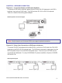
Chapter 9-1. Connection Between a DVR and a Keyboard ...................................... 53
Chapter 9-2. Daisy Chain Connections of DVRs and a Keyboard ............................ 53
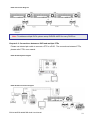
Chapter 9-3. Connections between a DVR and multiple PTZs .................................. 54
Chapter 9-4. Connection between multiple DVRs and multiple keyboards ............... 55
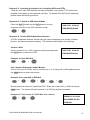
Chapter 9-5. Operating a Keyboard for Controlling DVRs and PTZs....................... 56
Chapter 9-5-1. Switch to DVR Control Mode ....................................................... 56
Chapter 9-6. Control DVR’s Multiplexer Features ..................................................... 56
Chapter 9-7. Control DVR’s Menu Setup .................................................................. 57
Chapter 9-7-1. OK or Cancel button in Submenu System.................................. 58
Chapter 9-8. Control DVR Playback.......................................................................... 58
Chapter 9-9. Control PTZ .......................................................................................... 59
Chapter 9-10. Control a DVR’s Spot Monitor ............................................................ 59
APPENDIX............................................................................................................................... 61
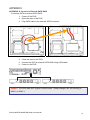
APPENDIX A. Connect to External SATA RAID................................................................ 61
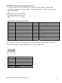
APPENDIX B. Connect External Alarm Switches ............................................................. 62
APPENDIX C. RS-485 Input and Output Pin Assignment ................................................ 63
APPENDIX D. Hard Disk Drive Support List..................................................................... 63
APPENDIX E. Supported DVD/RW Drive ......................................................................... 64
APPENDIX F. Hard Disk Recording Table ........................................................................ 64
SPECIFICATION ..................................................................................................................... 65
PDR-6160/PDR-6080/PDR-6040 User Manual
5
CHAPTER 1. SYSTEMS OVERVIEW
Chapter 1-1. Front Panel
Front View of PDR-6160 & PDR-6080
1
7
17
18
8
2
9 10
11
19 20
21
3
4
5
12
13
6
14 15 16
22 23 24
Front View of PDR-6040
18
1
2
7
23 3
1
5 15
3
10 9 8
PDR-6160/PDR-6080/PDR-6040 User Manual
4
24 22
12
13 16
6
1. LED status panel
Please see system LED status panel.
12. Down button
a. Move cursor down at menu mode.
b. Tilt down at PTZ control mode.
2. Split-display/camera buttons
13. Right button
a. 4, 8, 9, 13, 16 split-display when mode
a. Move cursor right in menu.
switch is on (PDR-6160 & PDR-6080
b. Pan right at PTZ control mode.
only)
c. Increase a value.
b. Camera selection mode
3. Left button
14. Shuttle ring (PDR-6160 & PDR-6080 only)
a. Move cursor left at menu setup.
a. Fast forward video at playback mode
b. Pan left at PTZ control mode.
b. Instant video FR or instant event list at
c. Decrease a value.
live mode
15. IR receiver
4. Enter button
a. Enter operation in menu setup.
b. Instant PTZ camera selection at live
mode.
c. Camera active mode
16. USB 2.0 connector
5. Up button
USB flash disk
a. Move cursor up in menu.
b. Tilt up at PTZ control mode.
6. Jog dial (PDR-6160 & PDR-6080 only)
17. Storage panel opening button
a. Play recorded image frame by frame
at playback mode.
b. Perform zoom in and out on a PTZ
device at live mode.
7. Rec button
18. Built-in DVD/RW drive
Start recording operation or stop the
recording task.
8. Play button
19. Emergency ejecting hole for DVD/RW tray
a. Invoke playback selection menu.
b. Replay after FF, FR, Pause, stepping
when playing video.
9. Pause button
20. Removable HDD tray
10. Stop video playback button
21. Removable HDD lock
11. Mode switch for split-display or
camera selection
(PDR-6160 & PDR-6080 only)
22. Menu button
23. ESC/shutdown button
24. Backup button
PDR-6160/PDR-6080/PDR-6040 User Manual
7
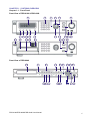
Chapter 1-2. Rear View
Rear View of PDR-6160
1
3
2
11
4
5 6 7
8
9 10
12
17
13 14 15 16
18
19
Rear View of PDR-6080
1 3
2
16 15
4
5 6 7
8
11
9 10
12
17
13 14
18
19
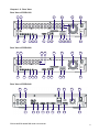
Rear View of PDR-6040
16
2
2
4
5
8
PDR-6160/PDR-6080/PDR-6040 User Manual
6
8
9
12
20
11
17
18
19
8
1. Spot/quad output
a. Spot/quad accessible by keyboard.
b. Each spot output can be
programmable for alarmed camera
display and sequence display.
2. Main output
3. External IR receiver (RCA)
4. Audio inputs
Four RCA audio connectors
5.
6.
7.
8.
9.
Audio output
PS/2 mouse
USB mouse
VGA output
Network RJ-45 connector
10. RS-485 out—PTZ devices
11. Alarm I/O
Alarm input switches, 1 N/O alarm
output, and 1 N/C alarm output
12. e-SATA connectors
Two e-SATA (PDR-6160 & PDR-6080)
connectors for external SATA RAID
One e-SATA for PDR-6040
13. RJ-45 Keyboard-in (PDR-6160 & PDR6080 only)
Connected from previous DVR’s
keyboard output in daisy chain.
14. RJ-45 Keyboard-out
Connect to the next DVR’s input.
RJ-45 connector
15. Looping—camera looping
16. Video in—16-channel analog video
17. Fan
18. Power switch
19. Power connector
AC 110V or 220V power input
20. Mouse input (top) / Reserved (bottom)
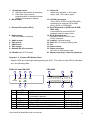
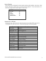
Chapter 1-3. System LED Status Panel
System LEDs are meaningful while operating the DVR. The status of each LED is described
as in the following table:
PDR-6160 and PDR-6080
1
2
4
ALARM HDD 1
PDR-6040
6
1
7
4
2
3
5
USB
POWER
REC
HDD 2
3
5
Item
1
2
LED
POWER
ALARM
3
4
5
6
7
REC
HDD 1
HDD 2
USB
BACKUP
Description
DVR power on/off indicator
External alarm switches indicators when
motioned or alarmed
Recording indicator
Master HDD recording indicator
Slave HDD recording indicator
USB portable disk connected indicator
Backup LED indicator (PDR-6040 only)
PDR-6160/PDR-6080/PDR-6040 User Manual
Color
Yellow
Red
Yellow
Green (blinking)
Green (blinking)
Green (blinking)
Green (blinking)
9
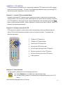
Chapter 1-4. Remote controller
The button arrangement of the remote controller is designed for easy-to-use purposes.
Buttons are separated in regions based on their features including DVR operational keys,
pan, tilt, and zoom camera device (PTZ) keys, numerical keys, and PTZ buttons.
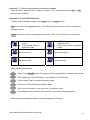
DVR operational keys (gray area)
MENU
ESC
Setup menu
Escape/exit
ZOOM
Digital video zooming
REC
Record/stop recording
FREEZE
Live video freeze
Pause
Playback
Stop
Fast forward
Fast rewind
Next single channel
Previous single channel
4 split display
8 split display
9 split display
13 split display
16 split display
PIP mode
SEQ
Sequential display
MUTE
Mute
AUDIO
Audio on
BACKUP
DVR
NTSC/PAL
LANGUAGE
PTZ features (yellow area)
Video backup
Addressable DVR control
Video system
Language selection
DVR & PTZ hybrid keys (blue area)
Auto Pan
Perform auto pan feature
Move up/tilt up
Zoom in
Zoom in of a fast dome camera
Move down/tilt down
Zoom out
Zoom out of a fast dome camera
Move left/pan left
Preset
Call preset of a fast dome camera
Move right/pan right
Enter/set
Numerical keys (green area)
0 to 9
Numerical keys
PDR-6160/PDR-6080/PDR-6040 User Manual
10
Chapter 1-5. Jog & Shuttle
Jog & shuttle menu—The DVR adopts Jog & Shuttle mainly in menu system and video
playback modes. In menu setup mode, rolling Jog is to move the cursor of the menu system
up or down. Shuttle moves the cursor of the menu system left or right.
Jog & shuttle during video playback-- During video playback, Jog & Shuttle acts as
conventional VCR for video stepping forward (rewind) and fast forward (rewind).
Instant rewind & event list modes—Turning shuttle ring left invokes Instant Rewind feature.
Instant Rewind rewinds and plays the recorded video from the moment of the operation in
backward. It allows that the operator can instantly review the video few seconds or few
minutes ago.
Turning shuttle ring right invokes event list (Instant Event). Operator can quick scan through
the event list for suspicious events. Instant Rewind and Instant Event features are identical
by pressing FF or FR button on the remote controller or a keyboard in live monitoring mode.
Jog for PTZ mode—Dialing jog dial in clockwise for a controlled PTZ camera can perform
zooming in action for the PTZ device. Dial jog dial in counter clockwise for zooming out
operation of the PTZ camera.
Chapter 1-6. Mouse System
The DVR has both USB and PS/2 mouse interface. A user can connect either USB mouse
or PS/2 mouse to operate the DVR. General mouse operations are described as below:
Left mouse click/
Right mouse click
Left mouse double click/
mouse drag
Mouse scroll
Left mouse click—In mouse menu system, mouse click can select a menu item. In windowdivision mode, click on a camera that is to select the camera in activation mode (active camera).
Left mouse double click-- In window division mode, click on a camera that can call the
camera in full screen mode.
Mouse drag—For channel editing, perform mouse drag that can drag one camera and
switch with another camera. In motion area setup mode, mouse drag can setup motion area.
Mouse scroll—In setup menu, mouse scroll can increase or decrease a value.
Right mouse click—Popup a submenu system or return to live in main menu.
PDR-6160/PDR-6080/PDR-6040 User Manual
11
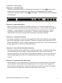
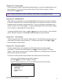
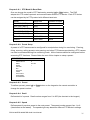
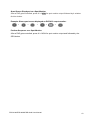
Chapter 1-6-1. Mouse Menu
For using mouse menu, please use the mouse click on Menu item. The mouse menu shows
on the screen for more system features.
LIVE
SETUP
PLAYBACK
MOTION
ZOOM
SEQUENCE
SHUTDOWN
Chapter 1-7. Active Camera
Active camera is shown in yellow color at the camera name/number in live monitoring mode.
Once a camera is activated, the camera can be controlled for PTZ operation or for camera
audio. Moving the active camera sequentially, one can simply press the Enter button on the
remote controller, the keypad, or keyboard(s).
PDR-6160/PDR-6080/PDR-6040 User Manual
12
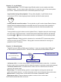
Chapter 1-8. Symbols & Icons
The DVR adopts symbols and icons for graphical user interface (GUI) design. These
symbols and icons contain useful information in operating the DVR. All the symbols and
icons are discussed in the rest of the chapter.
Task bar
The task bar shows up on bottom of the main monitor for indicating the operation status of
the DVR while operating the remote controller, the mouse, the keypad, or a keyboard.
The icons of the DVR are described in the follow table:
Mouse menu
Controlled DVR ID/RS-485 ID
The DVR’s ID/RS-485 ID address
Manual recording mode
Schedule recording mode
Zoom mode
Sequence mode
Remote controller preset mode
Network connection indicator
Audio on/off indicator
PDR-6160/PDR-6080/PDR-6040 User Manual
13
CHAPTER 2. DVR OPERATIONS
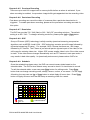
Most of the time, the DVR is operated at the surveillance/live mode. In live monitoring mode,
the information of screen layout and symbols are described in this section.
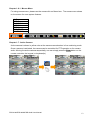
SCREEN LAYOUT
REC 2007/06/22 11:03:50
1
2
3
HDD 9%
4
5
①
Recording indicator
②
Date
③
Time
④
HDD recording percentage
⑤
Task bar
Chapter 2-1. Sequential Display
The DVR provides multiplexer feature displaying each camera in full screen
sequentially in specific time period. To perform sequential display, simply press
SEQ button on the remote controller or a keyboard. The sequence icon shows on
the task bar for indicating the DVR is in sequence status. To perform sequence
using mouse, please click on Mouse Menu->Sequence.
Chapter 2-2. Freeze
In live monitoring and playback modes, the DVR provides screen-freezing
feature in which suspicious individuals can be determined. To freeze the
screen, press Freeze button on the remote controller. Press the button
again to cancel this operation.
Chapter 2-3. Zoom
The DVR provides digital zooming capability in screen freezing, live monitoring,
and video playback modes. To perform this feature, press Zoom button on the
remote controller. Once the DVR is in zooming status, press Up, Down, Left, or
Right buttons to move the zooming window around to view other portion of the channel.
Press the Zoom button again can cancel the zooming window and back to normal screen.
To perform zoom feature using a mouse, please first double click on a camera channel for
camera’s full screen. Once the camera is in full screen mode, perform mouse drag on the video.
PDR-6160/PDR-6080/PDR-6040 User Manual
14
Chapter 2-4. CH+ & CHIn case of scanning through cameras in full screen, channel buttons, CH+ &
CH- can be used to monitor all cameras.
Chapter 2-5. Audio & Mute
Once the audio channel is properly setup, the DVR can output the live audio.
To disable live audio, one can press Mute button. To enable live audio,
press Audio button.
Chapter 2-6. Addressable DVR Control Button
To control one of the DVRs using only one remote controller, please press on the
addressable DVR control button followed by the DVR ID. The rest of the DVRs
are in sleeping mode until one of the DVRs gets called.
Chapter 2-7. NTSC/PAL
To change video system, press on NTSC/PAL button. Password is required if a
user presses on this button.
Chapter 2-8. Language
The DVR provides multi-language on screen display (OSD) support. To change
from one language to another, simply press on Language button.
Chapter 2-9. ESC/Shutdown Procedure
To properly shutdown the DVR, please press ESC/Shutdown button for a second. A
password dialog box shows up. Please provide administrator password to perform the task.
Power off the DVR without proper shutdown procedure that it may corrupt a video file. File
recovery procedure may start to recovery the video file when booting up the system.
Chapter 2-10. OK/Cancel Button
The DVR has OK/Cancel operation in menu/submenu system. To perform this operation,
the user can press Menu for OK or ESC for cancel on the keypad or the remote controller.
For keyboard, please press SET button for OK or CANCEL button for cancel.
PDR-6160/PDR-6080/PDR-6040 User Manual
15
CHAPTER 3. PTZ CONTROL
PTZ device can be controlled in live monitoring mode and PTZ setup mode via the keypad
and/or the remote controller. The rest of the chapter describes the ways of controlling PTZ
devices using the keypad and a remove controller.
Chapter 3-1. Instant PTZ Controllable Mode
Instantly controllable PTZ camera (active camera) is shown in yellow color at the camera
name/number in live monitoring mode indicating that the camera can be instantly controlled
for PTZ operations. Moving the active camera sequentially, one can simply press the Enter
button on the remote controller. Once a camera is in active mode (text in yellow), major PTZ
features can be easily performed.
Chapter 3-2. Remote Controller & PTZ
PTZ buttons are framed in yellow that contain auto panning, zooming, and zooming out.
Other PTZ and DVR buttons are shown in blue on remote controller. The details are
described as below:
1
5
6
4
3
7
2
①
Tilting the PTZ device up
②
Tilting the PTZ device down
③
Panning the PTZ device left
④
Panning the PTZ device right
⑤
Perform auto panning of the PTZ device
⑥
Perform zooming in of the PTZ device
⑦
Perform zooming out of the PTZ device
⑧
Calling presets
8
Chapter 3-3. Recall Presets
To call a preset, please follow the following instructions:
Press Preset button to enable the calling preset mode.
In Preset mode, preset 01 to 64 directly to recall preset points of the PTZ
device.
PDR-6160/PDR-6080/PDR-6040 User Manual
16
CHAPTER 4. RECORDING
Chapter 4-1. Start Recording
The DVR automatically performs recording task after power on. Press REC button on the
keypad or the remote controller that it can change the recording mode from schedule
recording to manual recording. Press REC button again. The DVR returns back to schedule
recording again.
Chapter 4-2. Manual Recording
Manual recording is equivalent to emergency recording. In manual recording mode, the
DVR records all the cameras based on recording frame rate. In many cases, there might be
a situation. A user might want to record all the cameras for suspicious events. Manual
recording can now be used for an emergency. If there are motion triggerings or alarm
switches set for the DVR, the events can be recorded in the DVR’s event log.
Chapter 4-3. Schedule Recording
For storage consideration, there are many applications that may be required to record video
after motion triggerings or alarm activations. Schedule recording can be used that the DVR
records video based on motion or alarm triggerings for certain hours. The schedule table can
be preprogrammed to meet the recording requirement.
Chapter 4-4. Alarm Switch Activation Recording
Recording operation can be triggered by an external alarm switch. An external alarm switch
can activate the DVR for recording. Proper settings such as Alarm Rec Duration and
activation type (N/O or N/C) should be configured before operation. Once one of the alarm
switches gets triggered, the alarm icon (yellow bell) shows at the bottom of each camera
channel.
Chapter 4-5. Motion Detection Recording
Motion detection is very useful feature of the DVR that the intrusion detection of a camera
can be detected. Motion detection recording sensors motion variation, and it triggers the
DVR to perform recording task. Once motion detection is activated, the motioned channel
shows an alarm icon (little man in yellow) on the screen to inform users.
PDR-6160/PDR-6080/PDR-6040 User Manual
17
CHAPTER 5. PLAYBACK
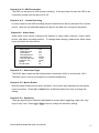
To playback, please press Play button on the remote controller, a keyboard, or the keypad.
A playback message box shows up for searching video clips. The details are described in
the following sections:
PLAYBACK
TIME SEARCH
EVENT SEARCH
RECORD SEARCH
DATE SEARCH
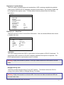
Chapter 5-1. Time Search
Time search feature can perform date and time search based on recorded video data. This
feature is very easy-to-use, and it allows a user to perform video searching task throughout
two hard disk drives. To perform time search operation, simply press Left or Right button on
the highlighted date or time field. To change the date and time, please press Up or Down
button.
TIME SEARCH
DATE
TIME
2007/09/11
19/54/00
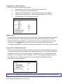
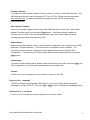
Chapter 5-2. Event Search
Event list contains information including date, time, event type, and camera channel for the
event. There are external alarm event and motion alarm event that can be found in event list.
To filter out events, please set starting and ending time in the event search dialog box. To
view operation log, please see System->Log View for detail.
EVENT SEARCH
RECORD TIME
05/07/04 13:40:48
05/07/04 13:40:42
05/07/04 13:40:35
EVENT
ALARM CH01
ALARM CH01
ALARM CH01
PDR-6160/PDR-6080/PDR-6040 User Manual
18
To select an event list item, press Up or Down button.
Press Enter button to play the video clips
Press Shuttle Left or << (FR) for previous page. Press Shuttle Left or >> (FF) for
next page on remote controller or keyboard.
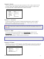
Chapter 5-3. REC Search
REC SEARCH contains the list when a user presses REC button to activate manual
recording operation. To play the REC Search list, please select Record Search item. A list
of start recording shows up accordingly. Press Up or Down button to select list item for
playback.
RECORD SEARCH
RECORD TIME
2007/07/04 13:39:47
2007/07/04 13:38:42
MANUAL
MANUAL
Chapter 5-4. Other Playback Features
Once one of above playback features is performed, features such as fast forward (FF), fast
rewind (FR), pause, stop, step, and re-play can then be used.
FF: Press Right button, shuttle ring right on the front panel, or FF key
on the remote controller to fast forward the playing video. The speed of
fast forwarding is range from 2X ~ 6X of the original playback speed.
FR: Press Left button, shuttle right left on the front panel, or FR key on
the remote controller to fast rewind the playing video. The speed of fast
rewinding is range from 2X ~ 6X of the original playback speed.
PDR-6160/PDR-6080/PDR-6040 User Manual
19
PAUSE & STEPPING: press Pause button while playing video that can
pause the video. Once the video is in pausing mode, one can press Left
or Right button on the DVR’s keypad or the remote controller to play the
video step-by-step.
Roll the Jog dial that can see the slow motion of the recorded video.
STOP: To stop video playback, press Stop button on the keypad or the remote
controller. The DVR’s screen switches back to playback main menu for other
playback operations. Press ESC button again that it returns to live monitoring
mode.
PDR-6160/PDR-6080/PDR-6040 User Manual
20
CHAPTER 6. MENU SYSTEM
Chapter 6-1. Setup Menu
Setup menu contains menu settings for camera, monitor, record, alarm, system, network,
PTZ, and backup. The details of all the setup menu items are described in the rest of the
chapters.
Record
Chapter 6-2. Camera Setup
One can setup individual camera’s settings such as camera name, video setup, sequence
display, video loss detection, and noise filter. To setup above, please select Camera menu
item in setup main menu.
CAMERA
CAMERA SELECT
CAMERA NAME
CHANNEL ENABLE
VIDEO SETUP
SEQUENCE TIME
V. LOSS DETECTION
NOISE FILTER
1
Cam01
ON
OFF
Chapter 6-2-1. Camera Name
A user can edit up to 12 characters for a camera name. To setup the camera name, please
type the character using visual keyboard and press Enter button.
Visual Keyboard
INSERT: CAMERA
1
Q
A
Z
2
W
S
X
3
E
D
C
4
R
F
V
5
T
G
B
6
Y
H
N
7
U
J
M
8
I
K
<
9
O
L
>
SPACE BAR
PDR-6160/PDR-6080/PDR-6040 User Manual
0
P
:
/
{
‘
=
}
:
Back
Cursor
OK
2
Enter
Page
21
Cascading Camera Name
In many cases, DVRs may be connected and accessed by keyboard(s) via RS-485. There
are up to 255 DVRs and 4080 cameras that can be addressed by keyboard(s). Editing
camera name becomes a time consuming task. The DVR can be automatically renamed by
using Cascading Camera Name (see System->DVR/RS-485 ID section).
Cascading Camera Name can match keyboard’s operating or calling convention. For
example, calling second DVR’s first camera can be done by pressing #2 + DVR + #1
Camera or #17 Camera. Directly calling camera is more intuitive. Cascading Camera Name
feature translates and modifies the second DVR’s camera name to CH17 to CH32.
For large-scale project, devices may include analog matrix, main monitor outputs, and spot
monitor outputs. The Cascading Camera Name feature is useful in identifying a camera.
However, a user can still use meaningful camera name instead of numerical value to identify
a camera.
Chapter 6-2-2. Channel Enable
Channel enable feature can disable the live video of a camera, and the channel can still
perform video recording. For privacy or security considerations, irrelevant people may be
prohibited to see the live video.
Chapter 6-2-3. Video Setup
Video setup can adjust video’s contrast, brightness, hue, and saturation for each camera. To
restore the default setting, please press Load Default menu item.
VIDEO SETUP
CONTRAST
BRIGHTNESS
HUE
SATURATION
LOAD DEFAULT
50
50
50
50
PDR-6160/PDR-6080/PDR-6040 User Manual
22
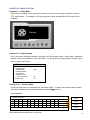
Chapter 6-3. Monitor Setup
The DVR has intellectual motion adoptive refinement with vivid image enhancement VGA
engine. The options can be set for the VGA engine including Adaptive Deinterlance, Edge
Preserving, Moving Object Correct, File Mode, LTI/CTI, and B/W Level Extension.
MONITOR
ADAPTIVE DEINTERLANCE
EDGE PRESERVING
ON
ON
MOVING OBJECT CORRECTION
FILE MODE
SHARPNESS ENHANCER
ON
ON
OFF
LTI/CTI
B/W LEVEL EXTENSION
MAIN MONITOR ALARM SWITCHING
OFF
OFF
MAIN MONITOR SEQ TIME
SPOT/QUAD SEQ
SPOT/QUAD SEQ TIME
SPOT
OFF
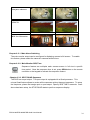
Each of the VGA settings is described in the following table:
OFF
ON
Adaptive deinterlance
Edge preserving
Moving object
correction
Film mode
PDR-6160/PDR-6080/PDR-6040 User Manual
23
Sharpness enhancer
LTI/CTI
B/W Level Extension
Chapter 6-3-1. Main Alarm Switching
The main monitor output can be configured in displaying camera’s full screen. To enable
this feature, please select the camera in camera selection box.
Chapter 6-3-2. Main Monitor SEQ Time
Sequence feature can multiplex each camera screen in full size in specific
time period. Once the sequence time is set, press SEQ button on the remote
controller or the keypad to activate the sequence feature.
Chapter 6-3-3. SPOT/QUAD Sequence
The DVR has a spot output. The spot output is equipped with a Quad processor. This
unique Quad feature allows to review all the cameras quicker than spot sequence. To setup
the sequence, please first assign spot or quad output. Specify SEQ TIME in seconds. Once
above has been setup, the STOP/QUAD starts to perform sequence display.
PDR-6160/PDR-6080/PDR-6040 User Manual
24
Chapter 6-4. Record Setup
Record setup menu can setup features related to recording features such as recording
quality, frame rate, recording mode, audio selection, alarm recording, recording resolution,
group of pictures (GOD), schedule table, HDD overwritten, and limited recording.
RECORD
CAMERA SELECT
QUALITY
FRAME RATE
RECORD MODE
AUDIO
PREALARM REC
POSTALARM
RESOLUTION
GOP
SCHEDULE TABLE
HDD OVERWRITTEN
LIMITED RECORDING
1
HIGH
7 / 120
SCHDEDULE
1
OFF
5 SEC
CIF
4
YES
Chapter 6-4-1. Record Quality
The recording quality can be configured for each channel. To change the quality setting,
press Left or Right button.
Chapter 6-4-2. Frame Rate
Each camera channel can be setup for its frame rate individually. To setup the frame rate,
please press Left or Right button.
FRAME RATE
CH1
CH2
CH3
CH4
CH5
CH6
CH7
CH8
8
8
8
8
8
8
8
8
←
←
←
←
←
←
←
←
→
→
→
→
→
→
→
→
CH9
CH10
CH11
CH12
CH13
CH14
CH15
CH16
8
8
8
8
8
8
8
4
←
←
←
←
←
←
←
←
→
→
→
→
→
→
→
→
□ AUTO
TOTAL: 120/120
Chapter 6-4-3. Recording Mode
Each camera can be setup for schedule recording or no recording. Once the recording
mode has been turned off, each recording mode including alarm, motion, or manual
recording does not record.
Chapter 6-4-4. Audio
There are up to four audio inputs that can be recorded into the DVR. To setup audio
recording, please assign the audio channel to a particular camera.
PDR-6160/PDR-6080/PDR-6040 User Manual
25
Chapter 6-4-5. Pre-alarm Recording
There are up to total 160 images held in memory buffer before an alarm is activated. If prealarm recording is enabled, the pre-alarm image buffer gets appended into the recording video.
Chapter 6-4-6. Post-alarm Recording
Post-alarm recording can record the video of a camera after a particular alarm/motion is
triggered. To enable post-alarm recording, please set the post-alarm recording seconds for
this option.
Chapter 6-4-7. Resolution
The DVR can provide 720 * 240 (field) or 360 * 240 (CIF) recording solutions. The default
setting is at 360 * 240. To change recording resolution, please press Left or Right button.
Chapter 6-4-8. GOP
Group of Pictures (GOP) technology is wildly used by dynamical streaming compression
algorithm such as MPEG-4 and H.264. GOP technology contains one still image followed by
dynamical streaming (P frame) . For example, GOP 4 means that there are 1 still image
followed by 3 P frames. The P frame is just a small portion (dynamic part of the video) of the
still image for reducing video size. Higher GOP means smaller video in size if the video source
is static. If the video source changes dramatically such as PTZ camera in auto pan mode, it
may results in bad video quality. In dynamically environment, please reduce GOP size.
Chapter 6-4-9. Schedule
Once the schedule has been setup, the DVR can record camera video based on the
schedule table. The DVR’s timer detects every second to check if it should start to record.
To edit the schedule table, a user can press Enter button for editing mode. Press Enter
button that can change recording mode, always, sensor, motion, or no record. For the Apply
All setting, the user can use Up or Down button to select Apply All menu item. Press Enter
button on Apply All menu item that can setup a recording mode for a week.
SCHEDULE
0 4 8 10 12 14 16 18 20 22 24
MON
TUE
WED
THU
FRI
SAT
SUN
□ ALWAYS
□
SENSOR
□ MOTION
□
NONE RECORDING
APPLY ALL
□
PDR-6160/PDR-6080/PDR-6040 User Manual
26
Chapter 6-4-10. HDD Overwritten
The DVR can be setup for HDD circular recording. If the user does not want the HDD to be
overwritten, please turn the option to be off.
Chapter 6-4-11. Limited Recording
In many countries, the HDD recording may be limited and can be only accessed for a certain
period. Once the recorded data passes the period, the data can no longer be accessed.
Chapter 6-5. Alarm Setup
Alarm setup menu allows changing the settings of extern alarm switches, motion alarm,
buzzer, and alarm recording duration. To change these settings, please enter Alarm setup
menu and follow the instructions:
ALARM
CAMERA SELECT
ALARM INPUT TYPE
ALARM ENABLE
MOTION SENSITIVITY
MOTION AREA SET
MOTION BUZZER TIME
ALARM REC TIME
BUZZER
BUTTON SOUND
CH01
OFF
OFF
OFF
NORMAL
05 SEC
05 SEC
ON
ON
Chapter 6-5-1. Alarm Input Type
The DVRs’ alarm inputs can be configured as normal open (N/O) or normal close (N/C).
The alarm input is one-to-one mapped to a camera respectively.
Chapter 6-5-2. Motion Enable
Motion Enable enables motion alarm activation, if the motion area has been set with proper
motion sensitivity. Press Left or Right button at Motion Enable menu item to change the
setting.
Chapter 6-5-3. Sensitivity
There are eight levels of sensitivity adjustable for motion alarm triggering, range from Very
High to Very Low. Press Left or Right button to change the sensitivity setting.
PDR-6160/PDR-6080/PDR-6040 User Manual
27
Chapter 6-5-4. Motion Area Set
There are few ways to setup motion area. The detail setup sequence is described as follows:
Step 1
Step 2
Step 3
Step 4
Step 5
Step 6
Step 7
Keypad
Keyboard
Remote controller
Enter Motion Area Set menu item.
Press Menu button again for motion setup selection.
Select “Motion Set” to define motion area(s)
Press Up, Down, Left, or Right to move cursor
(cursor mode).
Press Enter button to start area selection
Press Up, Down, Left, or Right for an area
Press Enter for cursor (cursor mode) and go to step
4 for second area. To exit the menu, please press
Exit menu item/ Menu button.
Mouse
Right mouse click.
Select a menu item using the
mouse.
Move mouse for starting
position.
Mouse drag for an area
Go to step 4 for second area.
Selection Exit menu item to save
changes and exit setup menu.
A user can also set or clear entire motion area by selecting Set All or Clear All menu item.
Chapter 6-5-5. Motion Tracer
Motion tracer can be used to determine the motion sensitivity. When motion tracer is set to
on, the motion grids are shown in red to represent motion triggers.
Chapter 6-5-6. Alarm Time
Motion alarms and external alarm inputs can trigger the buzzer alarm. Buzzer time is
adjustable from 0 to 99 sec. Press Left or Right button on Buzzer Time to adjust the time
setting.
Chapter 6-5-7. Buzzer Enable
In case, the warning buzzer requires to be turned off. A user can disable the buzzer under
System->Buzzer Enable menu item.
Chapter 6-5-8. Button Sound
To enable or disable button sound, please set button sound option.
PDR-6160/PDR-6080/PDR-6040 User Manual
28
Chapter 6-6. System Setup
The DVR system related settings such as date/time, HDD, restoring manufacturing default,
video format, DVR/RS-485 ID, language, password authentication, and firmware update can
be configured from system menu. To setup above features, please follow the following
instructions:
SYSTEM
DATE / TIME
HDD INFO
PASSWORD/ACCESS
LOG VIEW
FACTORY RESET
DVR / 485 ID
VIDEO SYSTEM
FIRMWARE
LANGUAGE
LIVE AUDIO
OFF
NTSC
ENGLISH
ON
Chapter 6-6-1. Date/Time
The DVR has built-in timer to record time information. One can choose different time format
or disable the timer.
DATE / TIME
TIME
DATE
FORMAT
DISPLAY
TIME SYNC
DST
18:16:17
2005 / 06 / 30
YYYY / MM / DD
ON
KEYBOARD
OFF
Time Sync
Time Sync feature allows the DVR to synchronize its timer system to PIH-931 keyboard. To
synchronize DVR’s timers to a PIH-931 keyboard, please set this option to Keyboard. PIH931D keyboard starts to synchronize every 15 minutes.
Warning: Highly recommend to perform Time Sync feature before the DVR starts to record
video.
Daylight Saving Time
The DVR provides Daylight Saving Time (DST) feature. This feature allows the DVR to
change timer system based on Daylight Saving Time table.
Warning: Highly recommend to re-format HDD, if the timer has been set and the HDD has
recorded video data.
PDR-6160/PDR-6080/PDR-6040 User Manual
29
Chapter 6-6-2. HDD Information
HDD INFO shows the following information:
1.
Model number—The model number of the hard disk drive
2.
Size—The capacity of the hard disk drive
3.
Approximate recording hour—recording hours based on the HDD(s)
4.
Approximate recording days—recording days based on the HDD(s)
5.
Average frame size—Average picture size
HDD INFO
PRI
MASTER
SIZE
SLAVE
SIZE
SEC MASTER
SIZE
SLAVE
SIZE
HDD FORMAT
APPROX REC HOURS
APPROX REC DAYS
RESET COUNTER
WD
250 GB
WD
250 GB
142
7
HDD Format
To format HDDs, please select HDD Format menu item. Password is required for preventing
unauthorized access. A warning message also gets prompted for formatting verification.
Please be alerted to this operation. It may erase not only event list data but also recorded
video data. Press Enter button at HDD Format menu to format the hard disk drives.
Formatting hard disk drives may take several seconds based on the number of lists recorded.
Chapter 6-6-3. Password/Access
The DVR has three sets of password protection (accounts) preventing unauthorized access.
To activate password function, please turn Enable Password on or off at System->Password.
The password consists of four to eight digits for entering the DVR. The default passwords
are admin, “1111”, operator, “2222”, and guest, “3333”. The acceptable characters are 1 to
10 (0) and A to Z. To change the password setting, please press Enter at System>Password->Change Password.
PASSWORD/ACCESS
USER
OLD PASSWORD
NEW PASSWORD
CONFIRM PASSWORD
PROPERTY
ENABLE PASSWORD
ADMIN
****
****
****
OFF
Note: In case, forgetting your password, please contact your sales agent for master password.
PDR-6160/PDR-6080/PDR-6040 User Manual
30
Access Property
Each account can be assigned for access rights including video playback, menu setup, video
backup, PTZ setup, network setup, and remote network playback. For an administrator, she
or he can manage various access rights for other users.
PROPERTY
PLAYBACK
SETUP
BACKUP
PTZ SETUP
NETWORK SETUP
REMOTE PLAYBACK
ON
ON
ON
ON
ON
ON
Chapter 6-6-4. LOG View
Operational event, video lose event, abnormal power off, and other DVR events can be
reviewed by LOG View menu item. Events are described in the following table.
Event
BOOTING
SHUTDOWN
ABNORMAL OFF
FORMAT
V.LOSS
WATCHDOG
SET CAMERA
SET MONITOR
SET RECORD
SET ALARM
SET NETWORK
SET SYSTEM
SET PTZ
SET BACKUP
ADMIN LOG
OPERATOR LOG
GUEST LOG
FILE RECOVERY
Description
Power on
DVR Shutdown
Abnormal power off
Format HDD
Camera video loss
Watchdog started
Set camera settings
Set monitor settings
Set recording settings
Set alarm settings
Set network settings
Set system settings
Set PTZ settings
Perform backup
Administrator login
Operator login
Guest login
File recovery after abnormal power down
PDR-6160/PDR-6080/PDR-6040 User Manual
31
Chapter 6-6-5. Factory Reset
A user may want to restore manufacturing default settings. A confirm message shows up for
final verification. To perform this task, please select Factory Reset at System->Factory
Reset and press Enter button.
Note: Factory reset does not affect IP address, video system, and language settings.
Chapter 6-6-6. DVR/RS-485 ID
Each DVR can be assigned by a unique DVR/RS-485 ID accessed by the remote controller
or PIH-931D keyboard. With a unique DVR/RS-485 ID set, the remote controller or PIH-931
keyboard issues commands to a particular DVR. The rest of DVRs are not affected by the
remote controller or PIH-931 keyboard. To operate addressable DVR control feature, please
refer to chapter 1 Addressable DVR Control Button.
To change DVR/RS-485 ID, press on Left or Right button on the front panel. Once DVR/RS485 ID has been change, the cascading camera message box gets prompted.
Chapter 6-6-7. Video System
The DVR supports both NTSC and PAL video systems. The DVR allows switching from one
video system to another without rebooting. To change video system, press Left or Right
button at System->Video System.
Chapter 6-6-8. Firmware Update
Firmware update allows one to upgrade the DVR’s firmware for improving system
performance. To perform firmware update, press Enter on Setup->System->Firmware
Update. There are two ways to perform firmware update via (1) USB flash disk at DVR site
and (2) HTML interface via network.
To perform firmware update using USB flash disk, please follow the instructions:
(1) Plug in portable USB disk at the DVR’s USB port.
(2) Press Enter button at Start Update Firmware.
(3) After finishing transferring, remove the USB device and reboot the DVR.
FIRMWARE UPDATE
USB FIRMWARE UPDATE
EXPORT SETUP
IMPORT SETUP
FIRMWARE VERSION
KERNEL
PDR-6160/PDR-6080/PDR-6040 User Manual
32
Prepare Firmware
To prepare firmware update, please create a directory, firmware, in the USB flash disk. The
USB flash disk should contain file system FAT-16 or FAT-32. Please visit the web site at
www.meritlilin.com to download the latest firmware and save the file in the directory
mentioned above.
Start Update Firmware
To perform firmware update, please plug in the USB flash disk into the DVR. Select Start
Update Firmware menu item and press Enter button. It will automatically transfer the
firmware into the DVR. After transferring firmware, wait until “Please Reboot System”
message gets prompted and reboot the DVR.
Export Setup
Export setup feature allows a user to export internal configuration into a system file, at USB
flash disk’s firmware directory. The file can later be imported to other machines. The
imported machine’s internal configuration gets updated based on the original DVR’s
configuration. To perform Export Setup, please select Export Setup menu item and press
Enter button.
Import Setup
To perform Import Setup feature, please select Import Setup menu item and press Enter key.
The configuration of the DVR gets updated based on the system file.
Version
Version menu item indicates the current version number of the DVR.
Chapter 6-6-9. Language
The DVR provides multi-language OSD support. A user can change his/her preferred
language to operate the DVR. Press on Left or Right button to change the Language setting.
Chapter 6-6-10. Live Audio
To turn on or off live audio monitoring, please set Live Audio option.
PDR-6160/PDR-6080/PDR-6040 User Manual
33
Chapter 6-7. Network
The DVR allows a user to access the video via Internet or LAN. In order to connect to LAN
or Internet, subnet mask, gateway, and IP address should be configured. Please consult
your Internet provider or system administrator for above information.
NETWORK
IP MODE
IP ADDR
SUBNET MASK
GATWAY
HTTP PORT
VIDEO PORT
MAC
STATIC
192 . 168 . 001 . 171
255 . 255 . 255 . 0
192 . 168 . 001 . 001
80
3100
00:0F:FC:00:00:03
Chapter 6-7-1. Port Number
For Internet connection, port number IP mapping technologies can be used for single IP
address shared by multiple devices via a network router. Please consult your network
administrator for this advanced network technique.
Note: Default Internet port numbers for the DVR are port 80 (HTML web pages) and port 3100
(video port)
Chapter 6-7-2. DDNS
To use domain name provided by DDNS server (www.dyndng.org), please first visit
www.dyndns.org to register an account. After registriation, please enter “host name”,
“username”, and “password” in DDNS menu item at DVR side.
Note: Please use lower case for “host name”, “username”, and “password” for both DynDNS
DATE
2007/09/11
TIME
19/54/00
registration
and DVR settings.
Chapter 6-8. PTZ Setup
The DVR can control up to 16 PTZ cameras. Using DVR’s keypad or the remote controller can
access all these cameras. To setup PTZ connection, please follow the following instructions:
PTZ
CAMERA SELECT
: 1
PTZ
: PIH 7625
PRESET ADJUST
BAUD RATE
9600
DIRECT KEYBOR ACCESS
PDR-6160/PDR-6080/PDR-6040 User Manual
34
Chapter 6-8-1. PTZ Model & Baud Rate
One can choose the model of PTZ devices by pressing Left or Right button. The DVR
adopts this PTZ model’s protocol and communicates with the PTZ device. Each PTZ device
can be assigned by its PTZ protocol with different baud rate.
Model
Baud Rate
Number of Bytes
PIH-7000 (MLP1)
9600
3
PIH-7600 (MLP1)
9600
3
PIH-7625-3 (MLP1)
9600
3
PIH-7625-7 (MLP2)
9600
7
PIH-7622-7 (MLP2)
9600
7
Pelco D
2400~9600
None
Pelco P
2400~9600
None
Chapter 6-8-2. Preset Setup
A preset of a PTZ camera can be configured for manipulation during live monitoring. Panning,
tilting, zooming, calling presets, auto panning, and other PTZ features provided by a PTZ camera
can also be accessed during live monitoring mode. All the features should be configured before
accessing PTZ functions. Please follow the rest of this chapter to setup a preset:.
PRESET SETUP
PRESET SETUP
DWELL
SPEED
POSITION
IRIS
AUTO IRIS
FOCUS
AUTO FOCUS
SAVE PRESET
CLEAR PRESET
01
000 SEC
1
Chapter 6-8-3. Preset
To define a preset, press Left or Right button on the keypad or the remote controller to
change the preset number.
Chapter 6-8-4. Dwell
Define dwell of a preset. Dwell number ranges from 0 to 255 (the shortest to the longest).
Chapter 6-8-5. Speed
Define speed of previous preset to the next preset. The speed number ranges from 1 to 8
(the slowest to the fastest). The speed might vary based on different PTZ device’s settings.
PDR-6160/PDR-6080/PDR-6040 User Manual
35
Chapter 6-8-6. Position
To adjust PTZ lens position, press Enter at Adjust Pos menu item. A PTZ screen keypad
shows up as a reminder. Please press Left, Right, Up, or Down button on remote controller
to move the PTZ lens. To zoom in and/or zoom out of the PTZ device, press Zoom In and/or
Zoom Out on the remote controller or Jog at front panel.
Chapter 6-8-7. IRIS & Auto IRIS
To adjust IRIS, please press Left or Right button on IRIS option. For auto IRIS, press Enter
on Auto IRIS option.
Chapter 6-8-8. Focus & Auto Focus
To adjust focus, please press Left or Right button on Focus option. For auto focus, press
Enter on Auto Focus option.
Chapter 6-8-9. Save Presets
Once the above parameters are entered, the lens of the PTZ device should be in place with
proper IRIS and focus set. To store the parameters permanently, please press Up or Down
button to choose Save menu item. The position gets stored by each PTZ device
programmatically. You can test the stored preset by switching back and forth on Preset
menu item. To define other preset point, please repeat chapter 6-8-4.
In live monitoring mode, this preset can be recalled at any time. To recall a preset, please
read Call Preset section for detail.
Chapter 6-8-10. Clear All Preset
To clear all the preset points of a PTZ device, please select Clear All Preset menu item.
Press Enter key on the front panel or remote controller. The operation clears all the preset
points.
Note: Please make sure that the RS-485 wires are properly installed and connected to the
DVR. The PTZ device ID is adjusted to the DVR’s camera number accordingly.
PDR-6160/PDR-6080/PDR-6040 User Manual
36
Chapter 6-9. Backup
The DVR provides various backup methods for performing backup task including USB flash
disk, DVD/RW (advanced model), and FTP file download.
BACKUP
DEVICE
CHANNEL
START
END
EJECT / LOAD
DVD/RW
ALL CHANNEL
2007/11/21 14:55
2007/12/21 14:55
□TRANSFORM TO AVI
TOTAL
274 MB
To perform backup, please press Left or Right to select backup device type. Press Enter
button on Channel option to select backup channel(s). Once the channel(s) has been
selected, enter start backup and end backup time. The video size will be calculated in Total
field. If an AVI backup file is needed, please select Transform to AVI option.
For DVD/RW backup, please purchase DVD+RW disk (recommended) .
Note: Windows Media Player can play AVI file. However, only one channel can be exported.
Chapter 6-9-1. FTP Download
If backup device is set to File, important backup video can be stored in DVR’s temporary
buffer. The DVR has 2 GB internal storage space allocated for file backup. The backup
files gets deleted automatically for the next time the backup task performed again.
To download the backup files, please use FTP program to download the video file to your PC.
Please provide the account and password as “Admin”, “Oper”, and “Guest” in the FTP
program to download the file(s). The user can also use integrated HTML interface for FTP file
download.
PDR-6160/PDR-6080/PDR-6040 User Manual
37
CHAPTER 7. FILE PLAYBACK
To play a backup file from a PC, a user can export DVR’s video to an AVI file or MPEG-4 file.
The difference between AVI file and MPEG-4 files are that AVI file can be played by Windows
Media Player Version 10 or above. However, there is only one single channel that can be
review. To review multiple channels, MP4Player.exe built-in in the DVR can be used.
Chapter 7-1. Play AVI File on PC
To play the AVI file on a PC, simply double click on the DVR exported AVI file. Window
Media Player loads the file and starts to play.
Note: To play AVI file, it requires Windows Media Player 10 or higher
Chapter 7-2. Play MPEG-4 Files
The DVR can export MPEG-4 file to (1) USB flash disk, (2) DVD/RW, (3) File for FTP
download. To play the exported MPEG-4 video files on a PC, please use MP4Player.exe .
MP4Player.exe can be copied over the backup device whenever the backup task has been
performed. The user can also download the application from the DVR’s HTML interface.
Chapter 7-2-1. Play MPEG-4 Audio
Double click on a channel in full screen for playing audio.
PDR-6160/PDR-6080/PDR-6040 User Manual
38
NETWORK
PDR-6160/PDR-6080/PDR-6040 User Manual
39
CHAPTER 8. NETWORK
There are two ways to access the DVR via network--Internet browser (web interface) or
CMX application. All the features including live monitoring, menu setup, video playback, and
file backup can be done by using web interface.
Chapter 8-1-1. Configuration
Make sure that network IP address, subnet mask, and gateway of the DVR are setup
correctly. Always, consult your network administrator before installing DVR.
To setup IP address, a user can use IPScan utility to scan all the DVRs within a LAN. This
powerful tool can help the user to monitor, to find, and to set IP configuration for all Merit
LILIN’s IP-based products.
Note: The default IP address of the DVR is 192.168.1.171
Chapter 8-1-2. Internet Ports
To access the DVR via Internet using a router, please make sure that IP Ports of the router
(IP sharing device) are set. The DVR uses the following IP Ports by default:
Port 80—HTML web pages
Port 3100—Command port
PDR-6160/PDR-6080/PDR-6040 User Manual
40
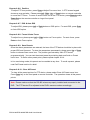
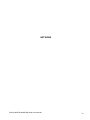
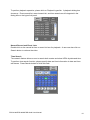
Chapter 8-2. Access the DVR via Internet Browser
To access the DVR, a user can use Internet browser to get live and stored video via Internet.
The DVR’s web interface also provides features of PTZ access, split window display, and
system configurations. General DVR web interface is described in the following figure:
Hyper Link Panel
Video Display Control
PTZ Control Panel
Camera Control Panel
Split Display Panel
PDR-6160/PDR-6080/PDR-6040 User Manual
41
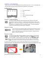
Chapter 8-2-1. Before Using Internet
Make sure that your Internet Browser allows signed ActiveX plug-in running on your PC. Set
“Download Signed ActiveX plug-in controls” to “Prompt” and “Run ActiveX control and plugin” to “Enable” at Internet Explore->Tools->Options->Security Settings.
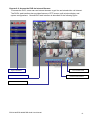
Chapter 8-2-2. Logon
To logon the DVR, please type in the IP address in the HTTP address box via Internet
browser. By default, type “192.168.1.171” in the HTTP address box to access the logon
page. Use default password “1111” for Administrator, password “2222” for Operator, and
password “3333” for Guest.
Note: Each user can be assigned for different access level at System->Password/Access.
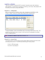
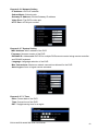
Chapter 8-2-3. Show Frame Size
To show frame size on each camera channel, please perform right mouse click on Video
Control Display area. A system menu shows up and select Show Frame Size menu item.
The frame size in Kbytes gets displayed on the right hand side of each camera caption. The
frame size information is very important information to determine bandwidth required for
operating the DVR.
PDR-6160/PDR-6080/PDR-6040 User Manual
42
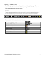
Chapter 8-2-4. Split Window Display Buttons
Buttons
Split Display
Buttons
Split Display
Single display
9 split display
4 split display
10 split display
6 split display
13 split display
8 split display
16 split display
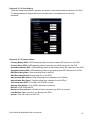
Chapter 8-2-5. Hyper Link Panel
Hyper Link Panel contains major features including video source, configuration, and
MP4Player.exe download page.
Configure the DVR via Web page
To configure the DVR via web page, please Click on “Configure” hyper link. There are
internal server setting, general network setting, PTZ device setting, and video system setting
allowed. The detail settings are described in the rest of the chapter.
Download MPEG-4 DVR File Player
MPEG-4 DVR File Player hyper link allows a user to download the application via Internet.
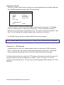
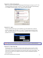
Chapter 8-2-6. Playback Over Network
The DVR allows a user to perform Play, FF, Pause/Step, and Stop operations on a remote
DVR. The buttons are described in the following figure:
Playback
Pause/Step
PDR-6160/PDR-6080/PDR-6040 User Manual
FF
Stop
43
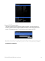
To perform playback operation, please click on Playback hyperlink. A playback dialog box
shows up. Event search list, record search list, and time search are all integrated in the
dialog box on the hyper link panel.
Normal Record and Event Lists
Double click on the record list item or event list item for playback. A user can also click on
Search button to retrieve the video.
Time Search
Time search feature allows a user to search both master and slave HDDs by date and time.
To perform time search function, please specify date and time information in date and time
edit boxes. Press Search button to finish this task.
PDR-6160/PDR-6080/PDR-6040 User Manual
44
Chapter 8-2-7. Save JPEG file
To save live or playback video to JPEG files, please perform right mouse click on Video
Display Control area. In system menu, select Save All as JPEG or Save JPEG for the live or
playback video.
Chapter 8-2-8. Network Audio
The DVR can provide network audio monitoring for both live and playback video. To activate
network audio, please open a camera’s video in full screen on Video Display Control. It can
deliver network audio to a PC for both live and playback video.
Chapter 8-3. Configure the DVR via Web page
Features of the DVR’s main menu system can be configured via web interface. Features
such as camera, alarm, recording, network, and backup can all get setup remotely.
Chapter 8-3-1 Camera Setting
Noise Filter—Enable or disable noise filter
Channel Enable—Enable or disable live video on main monitor
Sequence Time—Camera sequence time for main monitor
PDR-6160/PDR-6080/PDR-6040 User Manual
45
Chapter 8-3-2 Recording Setting
Current Rec Mode—Current DVR recording mode
HDD Overwritten—Option for circular recording
Camera Recording Mode--Assign schedule recording or no recording for a camera.
Camera Quality—Setup the recording quality for a camera
Camera FPS—recording frame rate for a camera
Chapter 8-3-3 Recording Schedule Table
A user can setup record schedule table via Internet, to setup scheduling table, please
specify day and time with the recording mode. The user can also use Apply
PDR-6160/PDR-6080/PDR-6040 User Manual
46
Chapter 8-3-4 Alarm Setting
Buzzer Enable—Enable/disable DVR buzzer
Motion Enable—Enable/disable motion detection
Motion Tracer—Enable/disable motion trace
Alarm Input Type—Set alarm input as NO/NC or disable
Buzzer Output Time—Assign buzzer time for each camera
Chapter 8-3-5 Alarm E-mail
Enable Alarm E-Mail—Option for enable alarm/motion email
From—From E-Mail address
To—To E-Mail address
Host/IP Address—SMTP mail server’s IP or DNS address
Authentication—Option for user and password authentication
E-Mail Account—receiver’s E-Mail account
E-Mail Password—receiver’s E-Mail account’s password
PDR-6160/PDR-6080/PDR-6040 User Manual
47
Chapter 8-3-6 Network Setting
IP Address—DVR’s IP address
Subnet Mask—Subnet mask
Gateway IP Address—Router/Gateway IP address
Video Port—The DVR’s video port
HTTP Port—HTML port number
Chapter 8-3-7 System Setting
MAC Address: MAC address of the DVR
Firmware: firmware version of the DVR
DVR/485 ID: Addressable DVR ID for multiple DVRs remote control using remote controller
and RS-485 keyboard.
Language: Language selection of the DVR
Max Connections: Maximum network connections allowed for the DVR
Auto Logout: force to logout remote accesses.
Chapter 8-3-7-1 Timer
Date: Current date of the DVR
Time: Current time of the DVR
DST: Daylight saving time for a region
PDR-6160/PDR-6080/PDR-6040 User Manual
48
Chapter 8-3-7-2 User Setting
There are three levels (admin, operator and guest) of user authentication allowed in the DVR.
To change password, please specify the old password, new password, and confirm
password.
Chapter 8-3-7-3 System Status
Primary Master HDD—HDD detecting status of primary master IDE channel for the DVR
Primary Slave HDD—HDD detecting status of primary slave IDE channel for the DVR
Secondary Master HDD—HDD detecting status of secondary maser IDE channel for the DVR
Secondary Slave HDD—HDD detecting status of secondary slave IDE channel for the DVR
HDD Recording Start—Start recording time of the DVR
HDD Recording End-End recording time of the DVR
Approximate Rec Hours—Total recording hours available for the HDD(s)
Approximate Rec Days—Total recording days available for the HDD(s)
Current Written HDD—The HDD of the DVR in writing
Already Overwritten—The HDD(s) has been overwritten.
DVR ID—DVR ID/RS-485 ID
Number of Connections—Number of users accessing the DVR via network
Last Reboot Time—Last time for rebooting the DVR
Kernel—The OS version of the DVR
PDR-6160/PDR-6080/PDR-6040 User Manual
49
Chapter 8-3-7-4 Firmware update
This DVR is allowed to perform firmware upgrade via network. After DVR receives the
firmware, it starts to perform firmware upgrade automatically. After finishing the firmware
update, HTML page gets reload. The user can then start to operator the DVR.
To perform network firmware update, please click on Browse button and locate the firmware.
For 4-channel, 8-channel, and 16-channel, the firmware files are flash604.bin, flash608.bin,
and flash616.bin respectively.
PDR-6160/PDR-6080/PDR-6040 User Manual
50
Chapter 8-3-8 Backup
To perform remote video file backup, click Backup hyperlink. Please specify starting time
and ending time. Click on Submit button to perform file backup task.
A backup progress bar shows up on the web page. After backup task ends, please click on
the file hyperlink with LMP file extension. It can download the file from the DVR’s internal
FTP server to your local PC.
To download the backup file(s) again, please click on “Backup File Download” hyperlink to
download.
DATE
TIME
2007/09/11
19/54/00
PDR-6160/PDR-6080/PDR-6040 User Manual
51
KEYBOARD CONNECTONS
PDR-6160/PDR-6080/PDR-6040 User Manual
52
CHAPTER 9. KEYBOARD CONNECTION
Chapter 9-1. Connection Between a DVR and a Keyboard
To operator a DVR with a keyboard, please directly connect PIH-931 keyboard to the DVR’s
keyboard input using a RJ-45 cable. The DVR provides DC 12V for PIH-931 keyboard.
There is no need for connecting power adapter.
DVR & Keyboard Connection Diagram
Note: Only 8-channel and 16-channel DVRs can support keyboard connection.
Chapter 9-2. Daisy Chain Connections of DVRs and a Keyboard
To connect PIH-931D a keyboard with multiple DVRs, connect the RJ-45 cable from PIH-931D
keyboard to the DVR’s RJ-45 keyboard input. The DVRs are connected in daisy chain from the
DVR’s keyboard output to the next DVR’s keyboard input. There are up to 255 DVRs can be
connected and addressed. For setup DVR/RS-484 ID, please read Menu->System->DVR/RS485 section first
DVRs System Diagram
PDR-6160/PDR-6080/PDR-6040 User Manual
53
DVRs Connection Diagram
Note: To address multiple DVRs, please setup DVR/RS-485ID for every DVR first.
Chapter 9-3. Connections between a DVR and multiple PTZs
Please use twisted pair cable to connect a PTZ to a DVR. The connections between PTZs,
please refer PTZs’ user manual.
DVRs & PTZs System Diagram
DVRs & PTZs Connection Diagram
PDR-6160/PDR-6080/PDR-6040 User Manual
54
Chapter 9-4. Connection between multiple DVRs and multiple keyboards
To connect multiple DVRs and multiple keyboards, please use Connector Box shipped with
the PIH-931D keyboard. Connections between keyboards, use a twisted pair cables to
connect two Connector Boxes. The detail is in the following connection diagram. The
connection between DVRs, please use RJ-45 cable to connect.
Multiple DVRs & Multiple PTZs System Diagram
Multiple DVRs & Multiple PTZs Connection Diagram
PDR-6160/PDR-6080/PDR-6040 User Manual
55
Chapter 9-5. Operating a Keyboard for Controlling DVRs and PTZs
There are four main DVR features including multiplexer, menu setup, PTZ control, and
playback controllable by the keyboard controller. To operate DVR by PIH-931 keyboard,
please follow the following sections:
Chapter 9-5-1. Switch to DVR Control Mode
Press the SHIFT button and the DVR button to set the
2006/01/01 12:00:00
keyboard controller to the DVR operation mode.
DVR MODE ID=000
+
Chapter 9-6. Control DVR’s Multiplexer Features
A DVR’s multiplexer features include calling a camera displayed on a monitor, windowdivision, and camera sequence display. The details are described in the following:
Control a DVR
Enter a number from 1~255 using the number pad and press
2007/01/01 12:00:00
the DVR button to select the DVR.
DVR MODE ID=xxx
Example: Control DVR #12.
+
+
Call a Camera Displayed on Main Monitor
After a DVR gets controlled, enter a number from 1 to 16 using the number pad and press
the CAM button to select the camera.
Example: Call camera #8 of DVR #12.
+
+
+
+
+
Directly access a camera of a particular DVR. Enter the camera’s ID (1~4080) and press
CAM button. The camera ID gets resolved to its DVR by keyboard controller.
Example #1: Call camera #17 (DVR #2’s first camera).
+
+
2006/01/01 12:00:00
DVR MODE ID=002
CAM=001
PDR-6160/PDR-6080/PDR-6040 User Manual
56
Example #2: Enter camera number 128 and press the CAM
2006/01/01 12:00:00
button. This calls DVR #8’s camera #16.
DVR MODE ID=008
CAM=016
+
+
+
Window-division on Main Monitor
To perform window division feature of a DVR, press the following window division buttons.
16 window-division
9 window-division
8 window-division
4 window-division (Quad screen)
DVR Sequential Display on Main Monitor
Press SEQ button to display cameras’ full screen in a sequence with specific time period.
Chapter 9-7. Control DVR’s Menu Setup
After a DVR gets controlled. Press the SET button to activate the DVR’s setup menu.
Menu Setup Using 3D Joystick
Enter a submenu
ESC/Exit a submenu
Move cursor up
Move cursor down
Decease a digit
Increase a digit
Enter a submenu
ESC/Exit a submenu
PDR-6160/PDR-6080/PDR-6040 User Manual
57
Chapter 9-7-1. OK or Cancel button in Submenu System
There are OK or Cancel button in submenu system. The shortcut buttons are SET or ESC
button on the keyboard.
Chapter 9-8. Control DVR Playback
To perform DVR playback feature, press Play button or Search button.
Play button can invoke playback menu. Use 3D joystick to move menu cursor and perform
playback feature.
Search button can invoke time search feature of the DVR. Use 3D joystick to move menu
cursor.
1. Enter a submenu in playback
menu
2. Fast forward video in
playback mode
1. ESC/Exit a submenu in
playback menu
2. Fast reverse video in playback
mode
Move cursor up
Move cursor down
Decease a digit
Increase a digit
Video Playback Operations
Pause: Press PAUSE button during playing video can pause the video in pause mode.
Play: Replay the video after Pause, Fast Forward, or Fast Rewind.
Fast Forward: Fast Forward the playback video.
Fast rewind: Fast Rewind the playback video.
Stop: Stop the playback video and return to playback menu.
Record/Stop Record: Perform DVR record or stop DVR recording operation.
Select various split display modes on live and playback monitoring.
PDR-6160/PDR-6080/PDR-6040 User Manual
58
Chapter 9-9. Control PTZ
To control PTZ camera in live monitoring mode, press Enter button to gain camera control
sequentially in window-division mode or perform call camera in full screen mode.
Once a camera of a DVR gets controlled, the following PTZ operations can be performed.
Zoom in
Zoom out
Tilt up
Tilt down
Pan left
Pan right
Zoom in
Zoom out
Focus far
Focus near
IRIS large
IRIS small
Auto Pan
Chapter 9-9-1. Recall a Preset
To recall a preset point of a PTZ device, please press number key and followed by Preset key.
Example #1: Recall preset #16 of camera #21.
+
+
+
+
+
Chapter 9-10. Control a DVR’s Spot Monitor
A user can also use a PIH-931D keyboard to control DVRs’ spot monitors. The spot monitor
is equipped with a Quad processor for quad screen accessed by a keyboard. Sequence
feature of spot monitor can also be accessed.
Call a Camera Displayed on a Spot Monitor
After a DVR gets controlled, press #1 + MON for spot monitor output and enter a number
from 1 to 16 using the number pad followed by the CAM button to select the camera.
Example: Call camera #8 displayed on DVR #12’s spot monitor .
+
+
+
PDR-6160/PDR-6080/PDR-6040 User Manual
+
+
+
+
59
Quad Screen Displayed on a Spot Monitor
After a DVR gets controlled, press #1 + MON for spot monitor output followed by 4 windowdivision button.
Example: Show quad screen displayed on DVR #12’s spot monitor .
+
+
+
+
+
Perform Sequence on a Spot Monitor
After a DVR gets controlled, press #1 + MON for spot monitor output and followed by the
SEQ button.
PDR-6160/PDR-6080/PDR-6040 User Manual
60
APPENDIX
APPENDIX A. Connect to External SATA RAID
To connect SATA to external SATA RAID:
1. Power off the DVR.
2. Open the case of the DVR.
3. Plug SATA cable to the external SATA connector.
4. Close the case of the DVR.
5. Connect the DVR to external SATA RAID using SATA cable.
6. Power on the DVR.
Caution: The DVR does NOT support N-RAID mode. Please change PSH-100’s setting to
RAID-0 or RAID-1.
PDR-6160/PDR-6080/PDR-6040 User Manual
61
APPENDIX B. Connect External Alarm Switches
For 8/16-Ch DVR, it has a D-SUB 25-pin I/O connector which contains 16 alarm switch
inputs (dry contact) and two alarm outputs. The detail description of the pin assignment is in
the following charts.
Alarm Switch Pin Assignment Table
Pin 1
Pin 2
Pin 3
Pin 4
Pin 5
Pin 6
Pin 7
Pin 8
Pin 9
Pin 10
Pin 11
Pin 12
Pin 13
Alarm input 1
Alarm input 2
Alarm input 3
Alarm input 4
Alarm input 5
Alarm input 6
Alarm input 7
Alarm input 8
Alarm input 9
Alarm input 10
Alarm input 11
Alarm input 12
GND
Pin 14
Pin 15
Pin 16
Pin 17
Pin 18
Pin 19
Pin 20
Pin 21
Pin 22
Pin 23
Pin 24
Pin 25
Alarm input 13
Alarm input 14
Alarm input 15
Alarm input 16
GND
ALARM COM
ALARM NC (normal close)
ALARM NO (normal open)
GND
GND
For 4-Ch DVR, it has 8-pin I/O connector which contains 4 alarm switch inputs (dry contact)
and two alarm outputs. The ping assignment is in the following charts.
Pin 1
Pin 2
Pin 3
Pin 4
Pin 5
Pin 6
Pin 7
Pin 8
Alarm input 1
Alarm input 2
Alarm input 3
Alarm input 4
GND
ALARM NO (normal open)
ALARM NC (normal close)
COM
PDR-6160/PDR-6080/PDR-6040 User Manual
62
APPENDIX C. RS-485 Input and Output Pin Assignment
Terminal
1
2
3
4
5
6
7
8
9
10
11
12
13
14
15
16
Name
----RS-485 – Out Link Keyboard
RS-485 + Out Link Keyboard
GND
DC +12V input
----RS-485 - DVR
RS-485 + DVR
GND
--
RS-485 PTZ Terminal Pin Assignment
Terminal
1
2
Name
RS-485 + for PTZ
RS-485 – for PTZ
APPENDIX D. Hard Disk Drive Support List
Model
HDD Size
Seagate Barracuda ST316020811AS
160GB
Seagate Barracuda ST3200827AS
200GB
Seagate Barracuda ST32506AS
250GB
Seagate Barracuda ST3400620AS
400GB
Seagate Barracuda ST3500630AS
500GB
Western Digital WD1600AVJS
160GB
Western Digital WD2500AVJS
250GB
Western Digital WD3200AVJS
320GB
Western Digital WD4000AVJS
400 GB
PDR-6160/PDR-6080/PDR-6040 User Manual
63
APPENDIX E. Supported DVD/RW Drive
Manufacturer
ASUS
Lite-On
NEC
Model
DRW-1608P3S
LH-20A1P
ND-3550A
APPENDIX F. Hard Disk Recording Table
Approximate recording days and hours can also be found at Menu->System->HDD Info.
Recording Quality
Very high
High
Normal
Low
Picture
size
8.2
KB/Pic
5.8
KB/Pic
2.9/Pic
KB/Pic
1.6
KB/Pic
120
GB
1.8
Days
2.5
Days
5.0
Days
9.1
Days
250
GB
3.7
Days
5.2
Days
10.5
Days
19.0
Days
400
GB
5.9
Days
8.4
Days
16.7
Days
30.3
Days
500
GB
7.4
Days
10.5
Days
20.9
Days
37.9
Days
750
GB
11.1
Days
15.7
Days
13.0
Days
56.9
Days
1000
GB
14.8
Days
20.9
Days
41.8
Days
75.9
Days
2000
GB
29.6
Days
41.8
Days
83.7
Days
151.7
Days
4000
GB
59.2
Days
83.7
Days
167.4
Days
303.4
Days
HDD
Note: #1. Recording frame rate is 120(NTSC)/100(PAL) picture per second at CIF in resolution.
#2. Above information may be inaccurate due to the installation environment.
PDR-6160/PDR-6080/PDR-6040 User Manual
64
Models
Recording medium
Recording mode
Speed
NRF
Resolution
Schedule
External RAID
Frame rate
Backup
DVD/RW drive
DVD format
Playback
Speed
Compression
Video Input
Camera Name
Looping
Live
Channel Editing
Video Out
VGA output
Multiplexer
Split screen
Spot
Alarm
Motion
Event
Recording
Accessories
P/T/Z protocol
Keyboards
IR receiver
RS-485/RS-232
Jog & shuttle
Mouse
Audio
Network
Protocols
Web setup
API
Web
IPScan
User authentication
WDT
DST
LRA
Multilanguage
CPU/OS
Power
Working Env.
Dimension
Weight
Specification
PDR-6160A/S
PDR-6080A/S
A: Removable HDD tray * 1, internal HDD * 1 with DVD/RW
S: Internal HDD * 2
PDR-6040A/S
A: Internal HDD * 1 with DVD/RW
S: Internal HDD * 2
SATA HDD: internal * 1 (A),
SATA HDD: * 2
Internal * 2 (S)
External alarm / motion detection / schedule / manual
PAL: 50 Field/Sec or 100 CIF/Sec NTSC: 60 Field / Sec or 120 CIF/Sec, 1.2 to 8.2 KB/CIF
Noise Reduction Filter, configurable for night
720*240 (Field) / 320*240 (CIF)
7 day * 24 hrs time table, recording mode configurable
e-SATA interface * 2 up to 4TB
e-SATA interface * 1 up to 2 TB
Configurable for each channel
USB 2.0 flash disk / DVD/RW (A) / FTP file download / Audio supported
4.0GB
DVD+RW, DVD+R, AVI/MPEG-4 video with ISO-9660 compatible, plug-n-play
Manual record, time search, event search, date search
FR: 2x, 4x, 6x / FF: 2x, 4x, 6x
MPEG-4
BNC * 16 (1Vp-p, 75Ω)
BNC * 8 (1Vp-p, 75Ω)
BNC * 4 (1Vp-p, 75Ω)
12 characters
None
BNC * 16 (1Vp-p, 75Ω)
BNC * 8 (1Vp-p, 75Ω)
PAL: 400 FPS NTSC: 480 FPS
PAL: 200 FPS NTSC: 240 FPS
PAL: 100 FPS NTSC: 120 FPS
Mouse drag-n-drop
1 BNC (1Vp-p, 75Ω)
2 BNC (1Vp-p, 75Ω)
Intellectual motion adoptive refinement with vivid image enhancement VGA engine
Sequence / digital zoom / freeze
4, 8, 9, 13, 16, PIP
4, 9, PIP
4, PIP
Spot with quad output, sequence, keyboard control, and alarm switching
None
Alarm in * 16 / out * 2 (NO/NC)
Alarm in * 8 / out * 2 (NO/NC)
Alarm in * 4 / out * 2 (NO/NC)
Motion grid 30*24 each channel, 8 sensitivities, motion tracer
External alarm, video loss, stop recording, power recovering, motion detection, schedule, logon, HDD format
Pre-alarm (up to 160 images) and post-alarm
Remote controller addressable up to 255 DVRs
Merit LILIN all series, Pelco P/D protocol, remote controllable, Web
Via RS-232
PIH-931 keyboard addressable up to 255 DVRs
None
Extra IR extension connector, up to 200 m
None
RS-485 keyboard connector * 2 , 12V output, RS-485 PTZ output * 1
PTZ connection
None
FF, FR, Step, instant rewind, menu setup
USB / PS-2, drag-n-drop, right-mouse-click, mouse wheel.
RCA * 4 input / RCA * 1 output (0.7Vp-p, 300 Hz to 3KHz)
Direct Internet browser access / multiple users access / free CMX / audio
ARP / TCP/IP / HTTP / SMTP / FTP/ DDNS
Full features with remote firmware upgradable
HTTP API / ActiveX / SDK supported
Live / event log & time search playback / AVI / snapshot
Supported, easy-to-setup for IP address
Three level: admin, operator, and guest, feature configurable
Hardware watchdog timer
Daylight saving time
Limited recording access
Supported
32-bit RISC Processor, 333 MHz/ Linux 2.6 Kernel
AC 110V / 220V Max., 135W
Temp: 0℃ ~ +50℃ / Humidity: 0%~80%
434mm x 411.4mm x 88mm
434mm x 411.4mm x 88mm
434 mm x 364.3 * 52.8 mm
8.5 Kg w/o HDD
8.5 Kg w/o HDD
5.2 Kg w/o HDD
PDR-6160/PDR-6080/PDR-6040 User Manual
65
66-6160CSE-1
DATE
TIME
2007/09/1
19/54/00
4/8/16-CH DVR CD-RW
PDR-6040/6080/6160 A/S
MERIT LILIN ENT. CO., LTD
http://www.meritlilin.com
66-6160CSE
INSTRUCTION MANUAL