1
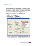
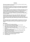
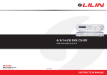
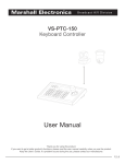
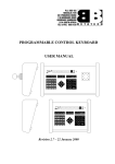
2.2 PTZ Camera Setup 2.2.1 Analog PTZ Camera Hardware Connection 1. Analog PTZ setup requires RS485 +/- connection from the PTZ camera to a GV-COM Box, GVNet Card, or GV-Net I/O Card. For GV-DVR system, GV-Net I/O Card can be found in the back of the unit. 2. From GV-COM Box, GV-Net Card, or GV-Net I/O Card, it is necessary to connect a RJ45 to RS232 cable or a RJ45 to USB cable to establish a connection to the DVR. 3. If RJ45 to USB cable is used, check under Device Manager for the correct COM port created. a. To access Device Manager, right-click on My Computer, select Manage, then select Device Manager. b. If RJ45 to RS232 cable is used, COM 1 is the default COM port. Add PTZ Device in Multicam 1. In Multicam, click on the “Configure” icon. 2. Select “Accessories ” -> “Add/ Remove PTZ”. 3. Select the appropriate PTZ protocol from the list on the left then click on “>>” to enable the PTZ protocol. 4. Click “OK”. 5. Restart Multicam by Last Settings. To verify PTZ protocol, refer to PTZ manufacturer user manual, technical document, or check with PTZ manufacturer directly. You may also find tested PTZ models in the next section. GeoVision Technical Handbook 13 6. Click on the “Configure” icon. 7. Select “General Setting” -> “System Configure”. 8. Under System Configure, place a checkmark by “PTZ Device Setup”. Then select corresponding PTZ protocol in the drop-down list. 9. Click on “PTZ Setup” button. 10. Check on “Active”. 11. Select “COM Port” for which the PTZ camera is connected through (refer to 2.2.1 step 3), and then select “Baud Rate” that matches the PTZ baud rate. 12. Click “OK”. To verify PTZ baud rate, refer to PTZ manufacturer user manual for options. It is typically setup via dipswitches on the PTZ camera. 13. Repeat above steps to add multiple PTZs using different protocols and COM ports. GeoVision Technical Handbook 14 For multiple PTZ cameras (with the same protocol) connected via the same COM port, it is necessary to assign a different ID (address) to each PTZ camera. In general, ID for each camera can be set via dipswitches on the PTZ camera. 14. At this stage, a PTZ button should appear on the right side of Multicam. Click on the button to bring up PTZ control panel to control PTZ via Multicam. To control a different PTZ, select the address from the drop-down list corresponding to the desired PTZ. If PTZ camera cannot be controlled, verify your hardware connection first. Then, verify that the protocol, COM port, and baud rate settings for your PTZ cameras are correct. PTZ Camera Mapping For DVR systems with more than one PTZ cameras, PTZ camera mapping will allocate each PTZ to its respective channels base on the address of the PTZ camera. 15. In Multicam, click on the “Configure” icon. 16. Select “Accessories” -> “PTZ Device”-> “Camera Mapping PTZ Dome”. 17. Under Camera Mapping Setup window, select the camera number with PTZ camera, then select “Device” and then the “Address” for the PTZ camera from the drop-down list. 18. Repeat step 17 for each of the PTZ cameras. 19. Click “OK”. Enable PTZ for Webcam 20. In Multicam, click on the “Network” icon. 21. Select “Webcam Server” to bring up Server Setup window. 22. Select “Video” tab, then click on “Allowed PTZ camera”. 23. Select individual camera to add or click on “Add all”. 24. Click “OK”. 25. Click “OK” again to exit Server Setup. For detailed instruction, refer to p.89 of v8.4 User Manual GeoVision Technical Handbook 15 2.2.2 Compatible PTZ Camera List GeoVision Technical Handbook 16 For PTZ cameras not listed above, users may try using generic protocols such as Pelco D or Pelco P. However, please be aware that generic protocols may or may not be able to perform the full functions in OEM PTZ cameras. Thus, users may observe loss of certain advanced features (such as OSD menu and auto-touring etc), if available. GeoVision Technical Handbook 17 2.2.3 Compatible Object Tracking PTZ Camera List GeoVision Technical Handbook 18 2.2.4 IP PTZ Camera In general, IP PTZ Cameras (or analog PTZ cameras connected via GV-Video Server or GV-Compact DVR) have the same setup procedure as IP cameras. (Refer to 2.1.2 IP Camera Setup). Then, after the IP PTZ cameras are connected to Multicam, follow the steps below: 1. In Multicam, click on the “Configure” icon. 2. Select “General Setting” -> “System Configure”. 3. Under System Configure, place a checkmark by “PTZ Device Setup”. 4. For IP PTZ Cameras: a. In the drop-down list, select the IP PTZ Camera model. (Please note the camera model will only appear in the list only if the camera is in our supported IP Camera List as shown in 2.1.3) 5. For analog PTZ cameras connected via GV-Video Server or GV-Compact DVR: a. In the drop-down list below, select the PTZ camera channel from GV-Video Server or GV-Compact DVR. (For example, if PTZ camera is on channel 1 of GV-Video Server, select VS01 in the list) 6. Click “OK”. 7. At this stage, a PTZ button should appear on the right side of Multicam. Click on the button to bring up PTZ control panel to control PTZ via Multicam. GeoVision Technical Handbook 19 2.2.5 PTZ Idle Protection 1. In Multicam, click on the “Configure” icon. 2. Select “Accessories” -> “PTZ Device” -> “Camera Mapping PTZ Dome”. 3. 4. 5. 6. Select the Camera to apply idle protection. Check “PTZ Inactivity”. Select the time period before idle protection activates. Select the desired function when idle protection starts by checking “Auto”, “Preset”, “Multi Position Tour”, or “Tour Schedule”. a. “Auto” allows the PTZ camera to Auto Scan, Frame Scan, or Random Scan. b. “Preset” will move the PTZ camera to a preset position. c. “Multi Position Tour” allows the PTZ camera to dwell over a series of presets with the ability to set dwell time for each location. d. “Tour Schedule” allows the PTZ camera to perform functions from a, b, and c by an hourly schedule. 7. Click “OK”. 8. Click “OK” again to finish setup. For detailed instruction, refer to p.90 of v8.4 User Manual GeoVision Technical Handbook 20