1
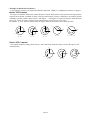
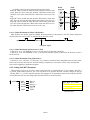
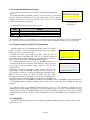
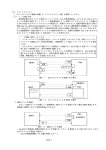
Part 2
Fics-III
System Setup
Table of Contents
1: Overview of Fics –III System Setup ..................................................................................... 3
2: Setting System Parameters ...................................................................................................... 5
2-1: Position Control Parameters ..................................................................................................... 5
2-1-1: Speed Parameters ....................................................................................................................... 5
2-1-2: Parameters for Acceleration and Deceleration...................................................................... 6
2-1-3: PTP Control with S-Curve Velocity Profile .......................................................................... 6
2-2: Setting Soft Limit and Offsets ................................................................................................... 7
2-2-1: Setting Software Limit .......................................................................................................... 8
2-2-2: Setting Home Offset .............................................................................................................. 8
2-2-3: Setting PTP Offset ................................................................................................................. 9
2-3: Setting/Checking Variables and FLAGs .................................................................................. 9
2-3-1: Setting/Checking Variables ................................................................................................... 9
2-3-2: Setting/Checking System Variables ....................................................................................... 9
2-3-3: Setting/Checking FLAGs .....................................................................................................11
2-3-4: Setting/Checking Monitor Variables ....................................................................................11
3: I/O Check ..................................................................................................................................... 12
3-1: Checking DI Status .................................................................................................................. 12
3-2: Checking DO Status ................................................................................................................. 12
3-3: Checking Drive Status, General I/O, and Sensors ...................................................................... 12
3-3-1: Checking Drive Status ......................................................................................................... 13
3-3-2: Checking Sensor Status ....................................................................................................... 13
3-3-3: Checking General DI/DO of Atom-series Drives ............................................................... 13
3-3-4: List of General DI/DO of Atom-series Drives ..................................................................... 13
3-4: Checking Error History ........................................................................................................... 14
3-5: Checking Communication Error ............................................................................................ 14
4: Listing ............................................................................................................................................ 14
5: Assigning I/O Module Channel Number (Fics-IOM) .................................................. 14
5-1: Fics On-Board I/O ................................................................................................................... 15
5-2: Configuring DI/DO of Fics-Atoms SB ................................................................................... 15
6: Setting Environmental Parameters .................................................................................... 15
6-1: Setting Coordinate Systems and Mechanical Parameters .................................................... 16
6-1-1: Setting Coordinate Systems ................................................................................................. 16
6-1-2 Automatic update of program data ....................................................................................... 19
6-1-3: Setting Micro Step ............................................................................................................... 20
6-2: Setting Homing, Moving Direction, and Coordinate Unit .................................................... 20
6-2-1: Home Mechanism................................................................................................................ 20
6-2-2: Setting JOG-KEY Parameter ............................................................................................... 21
6-2-3: Setting PULSE Parameter ................................................................................................... 22
6-2-4: Setting Coordinates System................................................................................................. 22
6-2-5: Setting Encoder Type .......................................................................................................... 22
6-3: Setting Bit Mask for Digital Inputs ........................................................................................ 22
6-3-1: Setting Bit Mask for DI ....................................................................................................... 23
6-3-2: Setting Bit Mask for General Inputs and Sensor Inputs(Fics-Atoms only) ........................ 23
6-3-3: Setting Continuous Monitoring for Emergency Stop and Motor Error............................... 23
6-3-4: Setting Manual Input and Output ........................................................................................ 24
6-4: Setting Parameters for RS232C Communication ................................................................. 24
6-5: Initialization.............................................................................................................................. 24
6-5-1: Initializing Program Area .................................................................................................... 25
-SYS 1-
6-5-2: Initializing Parameters ......................................................................................................... 26
6-5-3: Setting Number of Axes and Unused Axes ......................................................................... 26
6-5-4: Setting Unit Information...................................................................................................... 27
6-5-5: Version Information............................................................................................................. 28
7: Loading and Saving of Data to EEPROM ....................................................................... 29
8: Communication with WinFics .............................................................................................. 29
Appendix 1: More Information About Homing of Fics-Atoms Series ...................................... 30
Appendix 1-1: Error Messages for Homing .................................................................................. 31
Appendix 1-2: Axes Subject to Software Limit............................................................................. 31
Appendix 1-3: Switching to Automatic Mode ............................................................................... 31
Appendix 1-4: Home Completion Indicator................................................................................. 31
-SYS 2-
1: Overview of Fics –III System Setup
This chapter explains the system setup of Fics-series controllers by using the Fics-RT1, DYNASERVO universal
motion control terminal. DYNASERVO other handheld terminals (e.g. Fics-RT3/PT3), touch screen
controllers/terminals (e.g. Fics-TPC1), programming software tool WinFics etc. can also be used for system setup.
Since the screen size of each terminal is different, the menu arrangement may be different, but the parameters, which
have to be set, are the same.
Before you begin Fics-III programming, it is strongly recommended that you read through this chapter to fully
understand system setup requirements.
In the initial screen (cf. [2-1: Initial Screen], part 1), select [SYS] menu (by pressing <F3> key) to enter the
system setup mode (SYS mode). In SYS mode, various electrical, mechanical, and control parameters can be set and
their values can be checked. The status of variables, FLAGs, and I/O can also be set or checked.
The available commands for system setup are arranged in a tree structure as shown on the next page. The main
sub-menus and their functions are listed below.
Menu
PARAM
CHK
LIST
IOM
SETUP
Functions
Setting various parameters.
Setting maximum speed.
Setting acceleration and deceleration time.
Setting software limit.
Setting OFFSET.
Setting/checking variables and FLAGs.
Checking I/O data.
Checking drive status.
Listing existing and remaining programs steps.
Setting channel number for each connected I/O module
Setting environment.
Setting mechanical parameters (gear ratio, lead …).
Setting moving direction, homing mechanism etc.
Setting bit mask of DI.
Initializing program area.
Initializing parameters.
-SYS 3-
AUTO
MANU
SYS
PARAM
PTP/JOG
AXIS
SPD
SLOPE
CURVE
POS
AXIS
S-LMT
OFF
P.OFF
VAR
VAR
AXIS
AXIS
AXIS
NEXT
LAST
SYS/VAR
NEXT
NEXT
LAST
FLAG
MON
CHK
NEXT
LAST
EMG
NEXT
I/O /SNSR/BRK/DRV
CH+
AXIS
CHDO
N+
•–‚P Fics-Atoms SB ‚Ì‚Ý
N•–‚Q Fics-Atoms SB ‚Å‚Í•\ ¦‚³‚ê‚Ü‚¹‚ñ•B
RESET
IN
OUT
MOTOR
ERROR
WARN
LIST
•–‚P
DI/DO
IOM
DI/DO
IOM •–‚Q
SETUP
NEXT
LAST
DI/DO
M/C
NEXT
LAST
DI/DO
AXIS
DIV
ORG
AXIS
IN.P
EEPROM
PRM/PGM
LOAD
SAVE
J.KEY
PULSE
TYPE
INPUT
232C
INIT
CH
DI
MOTOR
EMG
I/O
PGM
PARAM
AXES
Ver.
-SYS 4-
•Ý’è‚Å‚«‚Ü‚¹‚ñ•B
Enc.z
(+/-)
NEED
SEQ
AXIS
KEY(+/-)
AXIS
PD/CW
(+/-)
AXIS
TYPE
AXIS
ABS/INC
NEXT
CH+
CH-
SNSR(I/O)
AXIS
NEXT
TYPE
INIT
ON/OFF
INIT
SAFE
NEXT
OK/NG
AXES
UNIT
STN
U.PGM
UNIT
U.MAX
USE
NEXT
U.MAX
AXIS
USER
ATOM
OPT
STN
2: Setting System Parameters
The [SYS]-[PARAM] menu is designed to set maximum speed for PTP/jog, accelerating and decelerating time etc.
2-1: Position Control Parameters
Position control requires velocity profiles to be specified. Fics-III supports S-curve as well as trapezoidal velocity
profile as shown below. To uniquely define these velocity profiles, it is necessary to specify maximum speed,
acceleration/deceleration time, and starting frequency (applies only to stepper motors).
Pulse rate
Maximum speed
Starting frequency
Decelaration time
Accelaration time
o
o
o
o
Time
These parameters should be independently set for each axis and for the following different motion:
Jog (manual)
Homing
PTP control (the maximum speed of each axis can be set independently.)
Interpolation (circular, arc, and linear interpolations, etc.)
2-1-1: Speed Parameters
The [PARAM]-[SPEED] menu: Setting the maximum speed and other parameters related to jog, homing, and PTP
control etc.
There are six parameters to be set for each axis. The axis is chosen by selecting [AXIS] menu. For item No.5 of the
following table selection of individual axis is meaningless since this item applies to all axis.
PARAM
SPEED
SLOPE
CURVE
-SYS- PTP AXIS
jog=xxxxmm/sec
[FAST]xxxxmm/sec
<X> org=xxxxmm/sec
PTP/jog
•yDDA•z
AXIS
AXIS
-SYS- jog AXIS
PTP MAX=xxxxmm/sec
jog key timer=xxxms
<X> one shot=xxxum
Speed Parameter
(in mm coordinate)
-SYS 5-
No.
Name
Description
1
2
3
jog
org
[FAST]
4
MAX
5
jog key
6
one shot
Setting maximum speed for jog operation
Setting maximum speed for homing
Setting maximum speed for jog operation when jog key is pressed and
held for longer than 1.5 seconds.
Setting maximum speed for PTP. The SPEED command in program
overwrites this parameter. Notice that the speed here refers to the speed
of the gear reducer output shaft.
Set one shot time to keep the jog operation. If jog key is pressed and held
for longer than the time specified in this field, jog operation continues.
Set moving distance if jog key is released within the time period
specified by jog key timer. This must be specified as a pulse number.
-SYS- jog AXIS
PTP MAX=xxxxmm/sec
one shot = n
<X>
-SYS- AXIS
ACCEL X:xxxxmsec
DECEL X:xxxxmsec
START-F X:xxxxpps
Speed Parameter
Accel Parameter
Note: If the coordinate system is set as “pulse”, the speed must also be specified by pulse rate in kpps.
2-1-2: Parameters for Acceleration and Deceleration
The [PARAM]-[SLOPE] menu: Setting acceleration time, deceleration time and starting pulse frequency on PTP
operation. These parameters are used for both trapezoidal and S-curve velocity profiles.
The startup frequency (START-F) applies only to Atom-PS(PDS) and Fics-PDS/3. SYS- AXIS
The acceleration and deceleration times in jog operation and homing process
ACCEL X:xxxxmsec
are both fixed at 100msec.
DECEL X:xxxxmsec
In systems with more than 1 axis, select [AXIS] menu to switch to other axes.
2-1-3: PTP Control with S-Curve Velocity Profile
By default, Fics-III uses S-curve as velocity profile because this usually generates
less mechanical vibration.
KIND: Selecting trapezoidal (LINEAR) or S-curve.
RATIO A (ACCEL): Specifying acceleration rate of S-curve.
RATIO D (DECEL): Specifying deceleration rate of S-curve.
For Fics-Atoms, the ratio parameter in the forth row is not displayed on the screen
because the acceleration rate and the deceleration rate are fixed at 50%.
Accel Parameter
(Fics-Atom)
-SYS<CURVE> KIND=0
(0:LINEAR 1:S-CURVE)
RATIO A=xxx%
D=xxx%
S-Curve Parameter
-SYS 6-
Pulse rate
Pulse rate
Maximum speed
Accelaration
Maximum
speed
Decelaration
Starting frequency
Unit msec Time
t
t
Accelaration time
(msec)
Fig. 1 Trapezoidal Curve
Decelaration timeTime
(msec)
Fig.2 S-Curve
2-1-3-1: Acceleration Rate (ACCEL=aaa%) and Deceleration Rate(DECEL=ddd%) in S-Curve
The acceleration and deceleration rates in S-curve velocity profile are specified by percentage.
0%
Acceleration: rapid starting and slow stopping.
Deceleration: slow starting and rapid stopping.
Acceleration: similar starting and stopping.
Deceleration: similar starting and stopping.
Acceleration: slow starting and rapid stopping.
Deceleration: rapid starting and slow stopping.
50%
100%
Pulse rate f
Maximum
0%
0%
Speed
50%
50%
100%
Accelaration time
100%
Decelaratoin time
Time
t
2-2: Setting Soft Limit and Offsets
Fics-III allows user to set software limit for safeguards, and home offset and PTP offset for convenience. Use
[PARAM]-[POS] menu to set these parameters.
1. SOFT LIMIT (software limit)
2. HOME OFFSET
3. PTP OFFSET
PARA
SPEED
SLOPE
CURVE
POS
Parameters 1 and 2 have the relation shown in the figure
below and can be set by entering numeric data or by teaching.
-SYS 7-
AXIS
S-LMT
OFFSET
PTP.OFF
AXIS
AXIS
AXIS
+OV (Y)
Hardware Limit
Software Limit
Software Home
Mechanical Home
-OV (Y)
-OV (X)
+OV (X)
o Mechanical home refers to the home position set by the homing process incorporating home sensor. Home offset
allows you to change the home position to the software home without changing the mechanical home position.
All coordinates in Fics-III are referred to software home.
o To set coordinates by teaching, homing must be completed first.
2-2-1: Setting Software Limit
The [POS]-[S-LMT] menu is used to set the software limit. Software limit
enhances safety by comparing target coordinates with the software limit before
starting any move. If the target coordinates in the program are out of the
software limit, motion does not start.
If the software limit coordinates are set to 0, the software limit will not be
checked.
2-2-2: Setting Home Offset
The [POS]-[OFF] menu: Setting the home offset. It is set to the coordinate
values of the software home.
2-2-2-1: Example of Setting Home Offset
When you want to set the software home as follows, the home offset reads
as (X=10.00mm, Y=8.00mm).
-POS- AXIS <CLR>
<SOFT LIMIT>
-X = ±xxxx.xxmm
+X = ±xxxx.xxmm
(mm-unit system)
-POS- AXIS <CLR>
<ORIGIN OFFSET>
X = ±xxxx.xxmm
(mm-unit system)
. Software Home
X = 10.00 mm
Y = 8.00 mm
8.00mm
10.00mm
Mechanical Home
o If the home offset is set as above, the homing triggered by <ORG> key on handheld terminal or by external DI
will move the axis first to the mechanical home, then move by the distance of home offset and set that position as
home. The current position after homing becomes (X= 0.00mm, Y= 0.00mm). However, the homing command
“ORIGIN (***)” in the Fics-III program only moves the axis to its mechanical home but does not move to the
software home. The coordinates after returning to the mechanical home become (X=-10.00mm, Y=-8.00mm). To
move the axis to the software home, use the PTP command to move to the position (0, 0).
-SYS 8-
o To set the software home by teaching, set the home offset as (0,0) at first. Then start homing, and move to the
position to be specified as the software home by pressing jog keys and then press <ENT> key.
2-2-3: Setting PTP Offset
The [POS]-[P.OFF] menu allows user to set PTP offset. The PTP OFFSET
can be used to shift coordinates of absolute PTP command. Because these
values are in terms of relative coordinates, they can be set by entering
numeric data, but cannot be set by teaching.
o In host control mode, specified absolute coordinates can be changed to other
points by changing this parameter.
PARAM
POS
VAR
-POS- AXIS
<CLR>
<POS OFFSET>
X =± xxxx.xxmm
Setting PTP Offset
NEXT
VAR
LAST
SYS
FLAG
NEXT
2-3: Setting/Checking Variables and FLAGs
In the [PARAM]-[VAR] menu, the values of variables and FLAGs can be set
or checked.
2-3-1: Setting/Checking Variables
There are 96 variables named VAR01~VAR96. These variables can be used
for arithmetic operation in application programs.
In the [VAR]-[VAR] menu, the value of variables can be set or checked.
Shown in the figure at the right are three variables. The display is scrolled up
by the [NEXT] menu and scrolled down by the [LAST] menu.
Do not use VAR96. This variable is reserved for internal use by the PALLET
(MATRIX) program
-SYS- NEXT LAST SYS
<VAR> 01:-xxxxxxxxxx
02:-xxxxxxxxxx
03:-xxxxxxxxxx
Setting/Checking Variables
-SYS- NEXT LAST VAR
<SYS> 01:xxxx02:xxxx
03:xxxx04:xxxx
05:xxxx06:xxxx
Setting/Checking
System Variables
2-3-2: Setting/Checking System Variables
There are 96 system variables named SYS01~SYS96. System variables provide flexibility to add custom features
to the system. Each system variable has special purpose. For example, SYS21/SYS22 are used to specify the
channel number and bit number of Auto/Manual control selector switch of the system. For details, refer to the
following table of system variables.
In the [SYS] menu, system variables are set or checked. System variables are updated and saved in EEPROM,
different from VARnn, which are saved in RAM. This feature, together with the aid of System Variables 65 and 66,
makes it possible to always use program parameters saved in EEPROM instead of using the program parameters in
RAM, which is on battery-backup when the power is off. If program parameters are stored in EEPROM, it is
necessary to save program parameters to EEPROM every time they have been changed.
-SYS 9-
System Variable No
SYS01/SYS02
SYS03/SYS04
SYS05/SYS06
SYS07/SYS08
SYS09/SYS10
SYS11/SYS12
SYS13/SYS14
SYS15/SYS16
SYS17/SYS18
SYS19/SYS20
SYS21/SYS22
SYS23/SYS24
SYS25/SYS26
SYS27/SYS28
SYS29/SYS30
SYS31/SYS32
SYS33/SYS34
SYS35/SYS36
SYS37/SYS38
SYS39/SYS40
SYS41/SYS42
SYS43/SYS44
SYS45/SYS46
SYS47/SYS48
SYS49/SYS50
SYS51/SYS52
SYS53/SYS54
SYS55/SYS56
SYS57/SYS58
SYS59/SYS60
SYS61
SYS62
SYS63
SYS64
SYS65
SYS66
SYS67
…
SYS69
…
SYS71/SYS72
SYS95/SYS96
Description
Remark
DO output channel /bit when running task 998
Atom ready input channel/bit
Execution suspend channel/bit
Automatic/Manu mode switching channel/bit
Demo operation channel/bit
Cycle operation channel/bit
Step operation channel/bit
Manual I/O ignore channel/bit
DO output channel/bit in automatic running mode
DO output channel/bit when error occurs
Power-off verification channel/bit
Pressure abnormal verification channel/bit
Servo-on channel/bit after power-on
Area sensor verification channel/bit
CPU status output channel/bit
RT1 connected/disconnected check channel/bit
Emergency stop of the same unit when error occurs
Treat<CAN> as emergency stop when homing
Treat <CAN> as immediate stop when homing
Load parameter from EEPROM at power-on
Load program from EEPROM at power-on
Treat emergency stop in the same way as pulse output type
Customization
Customization
Customization
Customization
Customization
Customization
Customization
Use (1) or do not use (0) on-board I/O as general input/output
Channel/Bit of JOG by external DI
Error reset channel/bit
-SYS 10-
Customization
2-3-3: Setting/Checking FLAGs
In the [PARAM]-[VAR]-[FLAG] menu, FLAGs can be set or checked.
FLAG is a variable with values of 0 or 1 only. There are 96 FLAGs.
FLAGs are expressed in programs as FLAGnn, where nn denotes a FLAG
number ranging from 01 to 96. FLAG00 is used by the system to indicate
the PTP is completed (0) or not (1). FLAG01-08 are reserved for system use
in multi-tasking.
Power-on check and EEPROM save are the same as variables.
-SYS-NEXT <0/1><CLR>
<FLAGS> 1
12345678 90123456
xxxxxxxx xxxxxxxx
Setting/Checking FLAGs
2-3-4: Setting/Checking Monitor Variables
In the [MON] menu, Monitor Variables can be set or checked.
Monitor variables are used mainly for various production management purposes.
2-3-4-1: Production Management Information
Production management information is stored in the monitor file only in WinFics.
There are 96 monitor variables named MON01~MON96 for production management. These variables can also be
used for purposes other than production management, but they are different from VARnn variables as far as the
arithmetic operation is concerned.
1 Capable of being uploaded or downloaded by WinFics.
2 No checksum for monitor files.
3 Cannot be saved to EEPROM
4 MON80~MON96 are used by Fics-III system.
Variable Name
MON80
MON81
MON82
MON83
MON84
MON85
MON86
MON87
MON88
MON89
MON90
MON91
MON92
MON93
MON94
MON95
MON96
Description
(system use: Power-on timer)
(system use: Automatic operation timer)
(system use: 1 Cycle duct time)
(system use: Unused)
(system use: Decrement timer)
(system use: Decrement timer)
(system use: Decrement timer)
(system use: Increment timer)
(system use: Increment timer)
(system use: Increment timer)
(system reserved: Unused)
(system reserved: Unused)
(system reserved: Unused)
(system reserved: Unused)
(system use: for I/O Wait command)
(system use: for I/O Wait command)
(system use: for I/O Wait command)
-SYS 11-
Unit
1 sec
1 sec
1 sec
10msec
10msec
10msec
10msec
10msec
10msec
2-3-4-2: Commands Related to Production Management
The following commands are related to production management.
(1) Timer control commands
(2) Monitor variable addition commands
(3) Monitor variable substitution commands
(4) Variable substitution commands
(5) Monitor variable branch commands
(6) I/O wait branch commands
3: I/O Check
In the [SYS]-[CHK] menu, the logic al state of input/output port, the status of motor drive, error history and the
number of communication errors can be checked.
CHK
IN
OUT
MOTOR
ERROR
WARN
NEXT
LAST
EMG
I/O SNSR/BRK/DRV
AXIS
DO
N.+
N.-
NEXT
CH+
CH-
RESET
3-1: Checking DI Status
By selecting the [CHK]-[IN] menu, the logical state of each input port can be
connected to the input port can be displayed and checked since the display is
updated continuously.
The [NEXT], [LAST] menu can be used to display the states of other input
ports if available. The relationship between a digital input and its logical state
can be inverted by the [INPUT]-[DI] menu to be stated in section [6-3].
checked. ON/OFF state of sensors
-CHECK- NEXT LAST
DI 76543210 76543210
01:xxxxxxxx xxxxxxxx
03:xxxxxxxx xxxxxxxx
Checking DI
3-2: Checking DO Status
In the [CHK]-[OUT] menu, the logical state of each output port is
displayed. Each bit can be set as '0' or '1' by entering the digit and then
pressing the <ENT> key. This operation turns ON/OFF each corresponding
DO port, which makes it easy to check the output port.
The [NEXT] and [LAST] menus can be used to display the states of other
remaining output ports if available.
Using the [CH+], [CH-] menus, cursor can be moved to the next or the
preceding channel.
3-3: Checking Drive Status, General I/O, and Sensors
In the [CHK]-[MOTOR] menu, drive states, general DI/DO,
sensor status can be checked (menu may differ for Fics-Atoms and FicsPDS/3).
-SYS 12-
-CHECK-NEXT CH+ CH<OUT> 76543210
01:xxxxxxxx
02:xxxxxxxx
Checking DO
-CHECK-I/O AXIS<CLR>
<MOTOR> STOP=x
ALARM=x READY=x
<X> SERVO READY=x
Checking Drive Status
3-3-1: Checking Drive Status
In this menu, the status of STOP, ALARM, READY, and
READY is displayed. “1” means “yes” and “0” means “no”.
SERVO
-CHECK-DRV AXIS
<MOTOR> ORG:0
+0V: 0
-0V: 0
3-3-2: Checking Sensor Status
The [SNSR] screen shows the status of home sensor, +overrun, and –
overrun sensors of each axis. “1” means ON, and “0” means OFF.
3-3-3: Checking General DI/DO of Atom-series Drives
The status of the general I/O of Atom -series drives can be checked by
selecting the [I/O] menu. To check an output port, move the cursor to the
desired DO bit and enter “0” or “1”. The logical state of each DI can easily be
inverted by appropriately setting the bit mask. See [6-3] for details.
Checking Home&Limit Sensors
-CHECK-SNSR AXIS DO
<MOTOR> 76543210
DI: xxxxxxxx
DO: xx
Checking Atom General I/O
3-3-4: List of General DI/DO of Atom-series drives
General
Input
DI: 7
DI: 6
DI: 5 DI: 4
DI: 3
DI: 2
DI: 1
DI: 0
Atom-SRA/SLA
Atom-SLIM
Ver.3.5
Atom-mini
Ver.3.5
Atom-PS Ver.2
Atom-PDS
Atom-PDS/3
Others
DI-8
DI-7
DI-6
DI-4
DI-3
DI-2
DI-2
DI-1
DI-1
DI-5
DI-1
DI-8
General
Output
DI-7
DO:6
Heat
Alarm
DI-5* 3
DI-5
DI-6
DO:5
DO:4
TIM
DI-3
DI-2
DI-1
DI-4
DI-4
DI-3
DI-3
DI-2
DI-2
DI-1
DI-1
DO:3
DO:2
DO:1
DI:0
Atom-SRA/SLA
STOP*1
READY*1
Atom-SLIM Ver.3.5
STOP*1
DO-1(SVRDY)*1
Atom-mini Ver.3.5
DO-1(Green LED)*1
Atom-PS Ver.2
Atom-PDS
Atom-PDS/3
Others
DO7*2
DO6
DO5
DO4
*1: Valid only when IO-TYPE parameter =1
*2: Valid only for the 3rd axis of PDS/3
*3: Does not exist for the 3rd axis of PDS/3
-SYS 13-
Current
Down
OFF
Hold
OFF
DO-1
STOP*1
READY*1
3-4: Checking Error History
In the [CHK]-[ERR] menu, the error history information can be
confirmed. Up to 16 error messages are saved. The latest error message is assigned
the smallest number ranging from 01 to 16. By selecting this menu, it is possible to
display the error history or to reset the history. The context displayed on the error
history screen is exactly the same error message that appeared on Fics-RT1 when
an error occurs.
[N+.]
[N-.]
[RESET]
-WARN- N+ N- RESET
STN:nn COUNT:99999
Display previous error message.
Display next error message.
Reset error history.
3-5: Checking Communication Error
In this menu, it is possible to check up to 65535 communication errors of
Atom drives. This feature is extremely useful for troubleshooting system
problems related to noise.
To reset the error of all drives, select station number by pressing
<F1>(N+)/<F2>(N-) and then pressing the <RESET> key.
-ERROR- N+ N- RESET
<01>
XXXXXXXXXXXXXX
Checking Error History
4: Listing
In the [SYS]-[LIST] menu, the program name and number of steps in memory
can be checked. As shown in the figure on the right, the program name, the
number of steps, and the number of available steps are displayed. To see more,
press <ENT> key.
“STEPS” indicates the total number of program steps in the selected program.
“REMAIN STEPS” shows how many program steps are available.
-LIST- PGM ALL LIST
PGM=001
STEPS=xxxx
REMAIN STEPS=xxxx
Listing Program Steps
5: Assigning I/O Module Channel Number (Fics-IOM)
MODUL
To activate DYNASERVO I/O modules for I/O control, it is necessary to
correctly set each module number by the DIP switch on module and assign the
channel number to each module.
If the [SYS]-[IOM] menu is selected; the screen shown on the right is
displayed and channel No. for each Fics-IOM can be assigned. “MDL00”
implies module number “00”.
Use [DI/DO] menu to select the type of Fics-IOM as either input type (FicsIOM/16 etc.), or input and output type (Fics-IOM/16.16CN etc.). The Fics-III
automatically displays the channel number of the first available channel for the
module in “xx” field. 8 bits DI/DO comprises one channel.
-SYS 14-
NEXT
LAST
-SYS-NEXT LAST DI/DO
I/O MDL00 16IO:xx xx
I/O MDL01 DI:xx
I/O MDL02 DO: xx
Assigning I/O Module (Fics-IOM)
Characters on Screen
Description
DO
8IO
16IO
16DO
DI
Module with 8 DO
Module with 8 DI and 8 DO
Module with 16DI and 16DO
Module with 16DO
Module with 16DI
5-1: Fics On-Board I/O
If there are on-board DI/DO on the Fics-series controller board, the on-board DI/DO are assigned channel No.
first. The channel No. assignment for DI/DO of Fics-IOM comes next. In this case, the DI of Fics-IOM is assigned
from channel No.5, and DO is assigned from channel No.3. The DI channel No.1-4 and DO channel No.1-2 are
assigned to the on-board DI/DO. If there are no on-board DI/DO, the channel numbers assigned to Fics-IOM starts
from “01”. Channel numbers are directly accessed in Fics-III application program.
Fics-Atoms SB Ver.3.5
24DI/8DO
Fics-Atoms PCI
IMC-1X
16DI/16DO
DI 76543210 76543210
01: cccccccc cccccccc
DI 76543210 76543210
01: cccccccc cccccccc
DI 76543210 76543210
01: xxxxxxxc xxxxxxxx
DI 76543210 76543210
01: cccccccc cccccccc
03: cccccccc xxxxxxxx
05: mmmmmmm mmmmmm
03: xxxxxxx xxxxxxxx
05: mmmmmm mmmmmmmm
03: xxxxxxxx xxxxxxxx
05: mmmmmm mmmmmmmm
03: cccccccc xxxxxxxx
05: mmmmmm mmmmmmm
DO76543210 76543210
01: cccccccc xxxxxxxx
03: mmmmmm mmmmmm
DO 76543210 76543210
01: cccccccc cccccccc
03: mmmmmm mmmmmmmm
DO 76543210 76543210
01: xxxxxxxx xxxxxxxx
03: mmmmmmm mmmmmm
DO 76543210 76543210
01: cccccccc cccccccc
03: mmmmmm mmmmm
cccccccc: Valid bit for on-board DI/DO
mmmmm: Valid bit Fics-IOM
xxxxxxxx: Invalid bit
5-2: Configuring DI/DO of Fics-Atoms SB
Fics-Atoms SB has 8 bits of digital inputs/outputs, which can be used either as digital inputs or as digital outputs.
Selecting the [SYS]-[SETUP]-[DI/DO] menu allows user to configure the DI/DO of Fics-Atoms SB as 24DI/08DO
or 16DI/16DO.
6: Setting Environmental Parameters
SETUP
The Fics-III is extremely flexible software, adaptable to different
motion control applications through the setting of specific application
parameters. Selecting the [SYS]-[SETUP] menu allows user to set
environmental parameters.
-SYS 15-
M/C
AXIS
INPUT
232C
INIT
AXIS
ORG
DI•@
MOTOR
PGM
6-1: Setting Coordinate Systems and Mechanical Parameters
-SYS- AXIS <CLR>
LEAD =xx.xxxmm/r
Fics-III supports the following four types of coordinate systems. Each axis can be ENCODER=xxxxxxp/r
assigned a different coordinate system. By default, all axes are set as “mm”.
<X>TIMES= x
6-1-1: Setting Coordinate Systems
mm
X=±xxxx.xxmm
Pulse
X=±xxxxxx
Angle
X=±xxx.x degrees
Tilt
X=±xxx.x degrees
mm Coordinate System
mm:
All coordinates are displayed in “mm”. Fics-III converts the coordinates on screen to output pulses automatically.
The following system parameters are needed for conversion.
LEAD
ENCODER
TIMES
Moving distance per revolution of motor
Encoder pulse number per revolution of motor
Magnification ratio of encoder (1, 2, or 4)
In mm-unit system, set LEAD equal to the pitch if ballscrew is used, or equal to circumference of the pulley for a
belt-drive axis. ENCODER is automatically set by Fics-III and cannot be changed once motor is selected. TIMES
specifies the magnification rate multiplied to the encoder pulse number. For example, if using an incremental
encoder, whic h generates 2500 pulses per revolution, and if TIMES is, by default, set as 4, then 10000 pulses
correspond to one revolution of motor.
The coordinates (X) on screen and the output pulse number (P) are related as follows:
P X*ENCODER*TIMES/LEAD
The result of divison is rounded off.
Pulse:
All displayed values on screen are results of multiplying the number of pulses by
-SYS- AXIS <CLR>
the system parameter RATIO. Conversion to output pulses is made by Fics-III
automatically by making use of the system parameter:
RATIO=xxxxxx:xxxxxx
RATIO = R1:R2
To display the actual pulse number, set RATIO as 1 : 1.
<X>
Assume one revolution of motor generates 1000 pulses. Then the minimum unit of
the on-screen value is 0.1 deg if the ratio is set as 3600 : 1000 or 36 : 10. The
Pulse Coordinate System
minimum unit of the on-screen value is 1.0 deg if the ratio is set as 360 : 1000 or 36
: 100.
The coordinates (X) on screen and the output pulse number (P) are related as follows:
P = X*R2/R1
The result of division is rounded off.
-SYS 16-
Angle:
Coordinates are displayed in degrees.
The sign of the coordinates indicates the rotation direction of the motor shaft,
-SYS- AXIS <CLR>
and the value represents the target position expressed in absolute coordinate. In
other words, the rotation range of the motor is 360 degree (one rotation), and the RATIO=xxxxxx:xxxxxx
coordinates can take possible values between –360 ~360 degree. For instance, if – GEAR= xxxx:xxxx
45 is specified, motor rotates 45 degrees from current position in the minus
<X>
direction. There are more examples to illustrate this concept.
Angle & Tilt Coordinate System
Assume one revolution of the motor generates 1000 pulses. Then the minimum
unit of the on-screen value is 0.1 deg if the ratio is set as 3600 : 1000 or 36 : 10.
Conversion to output pulses is made by Fics-III automatically by making use of system parameters RATIO =
R1:R2 and GEAR = G1:G2.
If using mechanical gear with gear reduction ratio equal to 40, GEAR should be set as GEAR=40:1.
The coordinates (X) on screen and the output pulse number (P) are related as follows:
P X*R2*G1/(R1*G2)
The result of division is rounded off.
Tilt:
Coordinates are expressed in degrees, but how many degrees to move is determined from both the target position
and the current position. For instance, if the current position is 45 degrees, and the target position is specified as –30
degrees, pulses corresponding to 75 degrees are outputted in the minus direction. There are more examples to
illustrate this concept.
Conversion to output pulses is made by Fics-III automatically by utilizing system parameters RATIO=R1:R2 and
GEAR = G1:G2.
The coordinates (X) on screen and the output pulse number (P) are related as follows:
P X*R2*G1/(R1*G2)
The result of division is rounded off.
-SYS 17-
<<Examples of Rotational Coordinates>>
In the following example, it is assumed that RATIO=3600:1000 GEAR=1:1 (1000pulse/per rotation, 0.1 degree).
Absolute PTP Command:
The sign of coordinates indicates the rotation direction of motor shaft, and the value represents the target position
expressed in an absolute coordinate. In other words, the rotation range of motor is 360 degree (one rotation), and the
coordinates can take possible values between –360 degrees ~ +360 degrees. To rotate to 0 degree in minus direction,
specify W=-360.0; To rotate to 0 degree in the plus direction, specify W=0.0, or W=360.0.
For instance, if –45 is specified, motor rotates 45 degrees from current position in the minus direction.
90
90
0
135
135
45
45
0,360
0,360
0
0
225
270
W = 225
W = -45
W=0
W = -360
W = -90
W = 360
Relative PTP Command:
The signed coordinates, taking values between –360.0 and 360.0, denote the relative value with respect to the
current position.
90
45
45
0
0
0
225
27
W = 135
-SYS 18-
W = -225
W = -360
<<Examples of Tilt Coordinate>>
Coordinates are expressed in degrees, but how many degrees to move is determined from both the target position
and current position. For instance, if current position is 45 degrees, and target position is specified as –30 degrees,
pulses corresponding to 75 degrees are output in the minus direction. Coordinates take values between –999.9 and
999.9.
Current
Position
0°
Target
Position
+30°
Angle Coordinate
Tilt Coordinate
Amount to
Move
30°
Amount to
Move
30°
0°
-30°
0°
330°
0°
30°
0°
90°
+30°
300°
9 0°
60°
9 0°
0°
0°
-30°
60°
9 0°
0°
120°
90°
0°
6-1-2 Automatic update of program data
Once mechanical parameters have been changed, programs in memory should be changed correspondingly. When
being asked whether program data should be automatically converted, press <ENT> key for yes . If unnecessary,
press any other key.
-SYS 19-
6-1-3: Setting Micro Step
For Fics-PDS/3, micro steps can be set. Selectable micro steps are shown below. By default, micro step is set as 50,
which means the number of pulses generated by step motor per one revolution equals the basic number of pulses
(e.g. 200 pulses) times 50. Therefore, one revolution will generate 10000 pulses.
1
8
30
100
1.5
10
32
125
2
12
40
150
2.5
12.5
48
160
3
16
50
200
4
20
60
250
5
24
64
400
6
6-2: Setting Homing, Moving Direction, and Coordinate System
AXIS
6-2-1: Home Mechanism
Homing process differs for different systems. Fics-III allows
user to select one of the following homing mechanism by
selecting [Enc.z] menu.
ORG
IN.P
J.KEY
PULSE
TYPE
Enc
No
Enc SENSOR
No SENSOR
Enc LIMIT
No LIMIT
Use encoder Z-phase
Do not use encoder Z-phase
Use encoder Z-phase, but do not make a U-turn at
sensor position
Do not use encoder Z-phase and do not make a Uturn at sensor position
Use encoder Z-phase and use the limit sensor as
the home sensor
Do not use encoder Z-phase, but use the limit
sensor as the home sensor
Enc.z
(+/-)
IN.P
KEY(+/-)
PD/CW
(+/-)
TYPE
-SYS-Enc.Z(+/-) NEED
<ORIGIN> X:Enc(-)
The [(+/-)] menu: Selecting rotation direction of homing.
The [NEED] menu: Selecting whether homing is needed before
automatic operation. If home offset is set, all axes move to the offset position after NEEDLESS PGM=999
returning to the mechanical home.
If, for example, homing is not needed, select NEEDLESS for home. Special care must be taken during operation
since home is automatically set to the position when power was turned on.
The [SEQ] menu: Selecting starting homing simultaneously for all axes or following the homing sequence as
specified in program 999 (PGM=999). Program 999 is executed by homing command or <ORG> switch (on FicsRT1 etc.).
6-2-1-1: Home Mechanism for Step Motor
If no Z-phase signal is available as in step motor, the arising edge of the home sensor is taken as the home position.
minus overrun sensor
home sensor
home position
There are three ways for returning to home depending on the starting point.
(1) Starting point is between the minus overrun and home sensor.
(2) Starting point is on home sensor.
-SYS 20-
plus overrun sensor
(3) Starting point is between home and plus overrun sensors.
Case (1): Move towards the minus direction. When the minus overrun
sensor turns ON, move in the plus direction. When home sensor turns
ON/OFF, move in the minus direction. When home sensor turns ON,
stop.
Case (2): Move towards the plus direction. When home sensor turns
OFF, move in the minus direction. When home sensor turns ON, stop.
Case (3): Move towards the minus direction. When home sensor turns
ON, move in the plus direction. When home sensor turns OFF, move in
the minus direction. When home sensor turns ON, stop.
Minus
Overrun
Home
Sensor
1
2
3
6-2-1-2: Home Mechanism for Motor with Encoder
When Z-phase (zero phase) signal is available, the home position is determined by the first Z-phase signal after
the first time home sensor is ON, as described in the previous section.
minus overrun sensor
home sensor
plus overrun sensor
zero phase signal
6-2-1-3: Home Mechanism with no Sensor U-Turn
If [Enc.Z] is set to “No.SENSOR” in case 3, the first sensor ON position is the home.
If [Enc.Z] is set to “Enc.SENSOR” in case 3, the detected encoder Z-phase position after the first time sensor is
ON is the home.
6-2-1-4: Home Mechanism Using Limit Sensors
If [Enc.Z] is set to “No Limit”, or “Enc.Limit”, it is possible to search for home using limit sensor as home sensor.
In this case, since the limit sensor is ON after homing is completed, it is necessary to move away from the limit
sensor at the beginning of application program.
6-2-2: Setting JOG-KEY Parameter
When pressing jog keys on Fics-RT1, motor rotates clockwise or counterclockwise. If, for example, when [X->]
is pressed, motor rotates clockwise, but if the movement in the opposite direction is desired, change the sign by
selecting [KEY (+/-)]. Notice that this operation only changes the correspondence between the JOG label and the
moving direction, but does not change pulse direction (PTP move direction) itself.
AXIS
ORG
IN.P
J.KEY
PULSE
TYPE
Enc.z
IN.P
KEY(+/-)
*1
PD/CW
(+/-)
TYPE
-SYS- KEY (+/-) AXIS
<COORD> X:(+)
JOG KEY +/JOG-KEY Menu
-SYS 21-
6-2-3: Setting PULSE Parameter
The [(+/-)] menu: Changing the sign of output pulse of each axis. This operation
will change the JOG and PTP move direction. If, for example, the coordinate value -SYS- (+/-) AXIS
displayed on Fics-RT1 is negative when motor is rotating clockwise, which is <PULSE> X:(+)
opposite to the desired direction, change the sign by selecting [(+/-)].
6-2-4: Setting Coordinates System
The [TYPE] menu: Setting coordinates system as mm, pulse, angular, or
tilt. The displayed coordinate system on screen is changed cyclically by
clicking [TYPE](<F1>) menu.
'mm'-> <F1> -> 'PULSE' -> <F1> ->'ANGLE'-> <F1> 'TILT'
mm unit for
linear
coordinate
All coordinates are expressed and displayed in “mm”
Pulse unit
All coordinates are expressed and displayed in number of
pulses
Degree unit for
angular
coordinate
All coordinates are expressed and displayed in degrees.
Notice that
1). Coordinates are displayed with value from 0 to 360 and
the sign indicates the direction of rotation.
2). Coordinates greater than 360 are displayed with the
remainder after divided by the number of pulses per
revolution.
3). In PTP operation, up to one revolution can be specified in
both absolute and relative coordinates.
Degree unit for
tilt coordinate
All coordinates are expressed and displayed in degrees, but
the movement measure depends on the current and target
coordinates. For details, refer to
the programming guide (part 3 of this manual)
Setting PULSE Parameter
-SYS-TYPE AXIS <CLR>
<COORD> X:mm
Setting Coordinates System
6-2-5: Setting Encoder Type
By selecting [ABS/INC] menu, the encoder type (absolute or incremental) can be specified for each axis. In a
multi-axis system, it is possible that some axes are using ABS motors while others ENC motors. In such case, it is
necessary to home before any automatic operation. For how to reset ABS encoder, etc. refer to DYNASERVO
Atom-series drive manual.
6-3: Setting Bit Mask for Digital Inputs
In Fics-III, sensor ON is represented by “1” and OFF by
“0”. The relationship between an input signal and its logical
state can be changed by setting the corresponding bit mask
with [INPUT]-[DI] menu.
-SYS 22-
SETUP
M/C
AXIS
INPUT
232C CH
INIT
DI
MOTOR
EMG
I/O
NEXT
CH+
CHAXIS
6-3-1: Setting Bit Mask for DI
Menu
[INPUT]-[DI]
[NEXT]
[CH+],[CH-]
Function
Setting bit mask as “0” or “1”.
By default, all bit masks are “0”.
Selecting other channels if available
Moving cursor to the next or preceding channel
-INPUT- NEXT CH+ CHDI 76543210 76543210
01:xxxxxxxx xxxxxxxx
02:xxxxxxxx xxxxxxxx
Setting Bit Mask for DI
The actual DI status is determined by XORing the sensor status and the
bit mask. For example, if some DI is of “normally closed” type, then Fics-III sees the DI is ON if the
corresponding bit mask is set as “0”. If, however, the corresponding bit mask is set as “1”, then in Fics-III, the
status of the DI is OFF because the status is determined by “1 XOR 1” which is “0”.
6-3-2: Setting Bit Mask for General Inputs and Sensor Inputs (Fics-Atoms only)
By selecting the [INPUT]-[MOTOR] menu, it is possible to invert the
general inputs/outputs of Atom-series drives by setting the bit mask for
these inputs. If the ON/OFF is opposite to the desired state, it can be
inverted.
-INPUT-DRV AXIS
<MOTOR> 76543210
DI:xxxxxxxx
<X>
Setting Bit Mask for Atoms General DI
-INPUT-IO AXIS <CLR>
<MOTOR> ORG: 0
+OV: 0
<X>
-OV: 0
In [SNSR] menu, the states of the home sensor (ORG) and overrun
sensors (+OV and –OV) can be inverted by properly setting their bit
masks. Press <F2> to select specific axis. In most applications, +OV and –
OV sensors are of “normally closed” type, so the bit mask for these sensors
Setting Bit Mask for Sensors
should be set as “1”. This way, under normal conditions (+OV and –OV
are OFF), the logic state of overrun sensors in Fics-III is “0” (= 1 XOR 1). If this is not set, jog error occurs when
trying to jog because Fics-III sees that both overrun sensors are ON at the same time.
6-3-3: Setting Continuous Monitoring for Emergency Stop and Motor Error
The [INPUT]-[EMG] menu: Setting bit mask for emergency stop switch
and conditions for continuous monitoring of emergency stop and motor
error. To reverse the logic state of emergency switch, set the “0” in the
second line of the screen on the right as “1” or “0”. When TIMER and
INPUT are set as “0”, the emergency stop and motor error are
unconditionally and continuously monitored. When the TIMER is not “0”,
the emergency stop and motor error are not monitored for the set time
period beginning from the moment of power-on. When the INPUT is not set
to “0”, the system does not monitor while DI:nn-m is “0” (OFF).
TIMER: Delay time for starting monitoring after power-on.
INPUT: External DI for monitoring.
-SYS 23-
-INPUT<CLR>
<EMERGENCY>:0
TIMER:000sec
INPUT:00-0
Setting Continuous Monitoring for
Emergency Stop and Motor Error
6-3-4: Setting Manual Input and Output
It is possible to control DO output by DI input in manual and programming
modes.
The maximum number of assignable points is 15. On each screen, 3 points can be
assigned. Inside the parenthesis of I/O (1), the group number of the 3 points is
displayed as shown on the screen on the right where “nn” and “m” represents
channel and bit numbers, respectively.
ON/OFF
ON
OFF
I:nn-m O:nn-m ON/OFF
I:nn-m O:nn-m ON/OFF
Setting Input and
Output Signals
In the [TYPE] menu, output mode can be selected.
Mode
I/O (1) NEXT TYPE
I:nn-m O:nn-m ON/OFF
Function
The state of DI is directly outputted to DO.
DO is enabled ON if DI is ON.
DO is enabled OFF if DI is ON.
For example, if I:01-3 O:01-5 ON/OFF is set, the ON/OFF of the DI bit 3, channel 01 is directly outputted to DO
bit 5. This is like software wiring, allowing for some specific DO to be directly controlled by some specific DI.
6-4: Setting Parameters for RS232C Communication
Fics-III communicates with WinFics and HOST option for PC-based
-SYScontrol via RS232C. The initial parameters such as baud rate, etc. in FicsIII are shown in the figure on the right.
<RS232C> 9600bps
Available baud rates: 19200, 9600, 4800, 2400, 1200, 600, 300. In
PO(0,2:PN 1:PO 3:PE)
controllers such as Fics-Atoms SB, there are two RS232C channels
DATA 8 STOP 1
(connectors): HOST and RT1. HOST is used for host communication and
Parameters for RS232C
RT1 is used for connecting to Fics-RT1 handheld terminal.
The HOST channel can also be used for Fics-RT1 connection if
-SYS- CH
<CLR>
selecting [CH] on the screen to change “HOST/WinFics: RT1” (the screen
on the right shows the default setting: HOST is used for host
communication).
HOST/WinFics:HOST
Parameters can only be changed for HOST channel. But when the
COMMAND WAIT t.tsec
HOST channel is used for Fics-RT1 connection and if the baud rate, etc.
are changed, it is necessary to change correspondingly the setting in FicsSetting HOST/WinFics CH
RT1 to match the speed, etc. When the setting does not match,
unrecognizable characters will appear on the screen of Fics-RT1. Once
the communication settings are changed, reset the power to Fics-RT1. To
change the baud rate, etc. of Fics-RT1, press SHIFT+CLR+MODE switches on Fics-RT1 keypad at the same time.
For Fics-RT1 channel, parameters: 9600bps, PN(No Parity), DATA =8bit, Stop=1bit are fixed and cannot be
changed.
For multi-unit option, the COMMAND WAIT parameter can be set. This command is designed for host
communication of Fics-Atoms. Specifically, if the ENQ command is sent out, and no ACK command is received
after waiting for a period of COMMAND WAIT time, the ENQ command is resent. If specified as 0.0sec, the ENQ
command will not be resent. For details of host communication, refer to DYNASERVO host communication user’s
manual.
6-5: Initialization
The [SETUP]-[INIT] menu allows user to initialize the program and parameter areas in memory and to set the
number of axes, etc.
-SYS 24-
6-5-1: Initializing Program Area
INIT
Fics-III allows the use of up to 999 programs. By default,
PGM=001~100 are designated as main programs, and the
remaining are designated as sub-programs.
PGM
PARAM
AXES
Ver.
INIT
SAFE
NEXT
INIT
ON/OFF
MOTOR
AXES
USER
6-5-1-1: Setting Range of Sub-Program Number
Set the specified program numbers as sub-program numbers. Other numbers are used in the main program.
The relationship between the first and last program numbers is as follows.
-SYS- INIT SAFE NEXT
SUB PGM:000->000: Sub-program does not exist.
SUB PGM:001->099: Sub-program are from PGM=002 to
<PROGRAM>
PGM=099.
SUB PGM:sss->eee
SUB PGM: 900->099: Sub-program are from PGM=900 to
PGM=999 and PGM=002 to PGM=099.
Setting Range of
PGM=001 is always a main program
Sub-Program Numbers
6-5-1-2: Initializing Program
The [INIT]-[PGM]-[INIT] menu is used to initialize the program area. When this
menu is selected, the screen on the right is shown to confirm the initialization. To
initialize, press <DEL> key. To cancel the initialization, press any other key.
When a program is PROTECTED, the program area cannot be initialized.
-SYS- INIT SAFE
<PROGRAM>
initialize OK ?
(OK: DEL)
Initializing Program
6-5-1-3: Protecting program
This function enables user to protect programs from being accidentally
erased.
The [INIT]-[PGM]-[SAFE] menu: Setting protection for programs from
being changed and from being copied. Program changing protection is set by
specifying the range of program numbers. Copy protection is set by selecting
[OK]/[NG] menu. Initial values are 000->000 and OK.
-SYS- NG
<PROGRAM>
PROTECT:sss->eee
COPY:OK
Protecting Program
-SYS- INIT ON
PROTECT: 000->000: No programs are protected.
<PROGRAM>
PROTECT: 100->999: Programs from PGM=100 to PGM=999 are protected.
PROTECT:OFF
PROTECT: 900->100: Programs from PGM=900 to PGM=999 and from
PGM=001 to PGM=100 are protected.
6-5-1-4: Setting Startup and Emergency Programs
In the [INIT]-[PGM]-[NEXT] menu, the user can set the startup program
to be executed at the time of power -on and the program to be executed in
an emergency.
If the value is set as “000”, the last “current program” is executed at the
time when power-on and the emergency stop error occurs in an emergency.
-SYS- NG
<PROGRAM>
POWER ON:000
EMERGENCY:000
Setting Startup Program
POWER ON:
EMERGENCY:
The program to be executed as current program at the
time of power-on.
The program to be executed in an emergency.
The emergency program is special program and has
several restrictions.
-SYS 25-
OK/NG
AXIS
OPT
(1) In an emergency, the emergency program is started after turning on the error stop indicator output bit.
(2) The commands, which can be used in the emergency program, are restricted to the same class of commands
that can be used in task programs except PTP commands.
(3) While emergency program is being executed, the emergency stop switch is not monitored.
(4) When the emergency program is registered, nothing is done for DO after the error reset. The DO can be
processed in the emergency program.
(5) When no emergency program is registered, all outputs of DO are turned OFF when error is reset.
6-5-2: Initializing Parameters
The [INIT]-[PARAM] menu allows the user to protect and initialize parameters.
6-5-2-1: Protecting Parameters
This function enables the user to protect parameters from being accidentally erased. If PROTECT is set to ON,
parameters can be viewed, but cannot be changed.
6-5-2-2: Initializing Parameters
The [INIT]-[PARAM]-[INIT] menu is used to initialize the parameter
area. When this menu is selected, the screen on the right is displayed to
confirm the initialization. To initialize, press <DEL> key. To cancel the
initialization, press any other key. When parameters are protected, the
parameter area cannot be initialized.
Once initialized, the message is displayed as shown on the screen. Press
any key to return to the initial screen.
-SYS- INIT ON
<PARAMETER>
Initialize OK
(OK: DEL)
-SYS- INIT ON
<PARAMETER>
PARAM initialize
Enter key to reset.
Initializing Parameter
6-5-3: Setting Number of Axes and Unused Axes
-SYS- AXIS
No. of AXES is n
The [INIT]-[AXIS] menu is used to set the total number of axes in the
system configuration and to specify unused axes.
When the number of axes is changed and the <ENT> key is pressed,
the message is displayed as shown on the screen on the right.
-SYS- AXIS
In Fics-III, once the number of axes has been changed, the system
returns to the initial screen by pressing <ENT> key.
6-5-3-1: Setting In-Use and Unused Axes
When a system is still under construction, it might be necessary to test
only the running part of the system. In that case, it is possible to specify the
unused axes. After moving the cursor to the axis you want to set, pressing
the [AXIS] key enables you to set the in-use axes (with axis names
displayed) and unused axes (with * displayed). The screen on the right
shows that currently X-axis and Z-axis are used; others are not used (even if
connected, they are not recognized by Fics controllers).
-SYS 26-
Parameter is changed.
Enter key to reset.
Setting Number of Axis
-SYS- AXIS
USE AXIS (X*Z*)
Setting In-Use and
Unused Axes
6-5-4: Setting Unit Information
In Fics-III, a system comprised of up to 16 axes can be divided into 5 units with a maximum of 6 axes in each unit.
By selecting the [INIT]-[AXES] menu, the following unit information can be set.
INIT
o Number of unit
o Number of axes in each unit
o Setting in-use/unused axes for each unit
o Program number for each unit
Once all this information is set, Fics-III assigns each axis a
unique station number.
PGM
PARAM
AXES
AXES
UNIT
STN
U.PGM
UNIT
U.MAX
USE
NEXT
U.MAX
AXIS
Ver.
6-5-4-1: Setting/Checking Unit Information
By selecting [INIT]-[AXES] menu, the information for each unit can be set or checked.
[AXES]
Setting the number of axes for the displayed unit
-SYS- AXES UNIT STN
[UNIT]
Changing unit numbers. “x/x” stands for “Unit
Number/Total Number of Units”.
UNIT No.=x/x
[STN]
Displaying station number for confirmation
[U.PGM]
Displaying program number for use by the unit
No. of AXIS is n
Setting No. of Axes for Each Unit
6-5-4-2: Checking Station Number for Each Unit
Selecting the [INIT]-[AXES]-[STN] menu enables user to confirm the
station number of each axis in each unit. The station number is
automatically assigned by Fics-III according to the total number of axes in
each unit. A station number will be displayed for axis in use; “-“ is
displayed for axes not in use; Axes not assigned to the system are
displayed with “**”.
[UNIT]
[U.MAX]
[USE]
Changing unit number
Setting maximum unit
Setting in-use/unused axes
-SYS- UNIT U.MAX USE
UNIT No.=1/1
<STN X:01 Y:-- Z:03
No.> W:-- U:** V:**
Station No. Confirmation
-SYS- U.MAX <CLR>
UNIT MAX : m
Setting Unit Number
-SYS 27-
6-5-4-3: Setting Unit Number
Set the total number of units to be used in a specific system. A maximum
of 5 units can be set. A maximum of 6 axes can be set in each unit.
-SYS- AXIS
UNIT No=x/x
USE AXIS( X*Z*)
6-5-4-4: Setting In-Use/Unused Axes
Setting In-Use/Unused Axes
When a system is still under construction, it might be necessary to test part
of the system. In that case, it is possible to specify the uninstalled axes as unused axes. Moving the cursor to each
axis and pressing [AXIS] menu enables the setting of in-use (with axes No. displayed) axes/unused axes(with *
displayed).
6-5-4-5: Setting Program Number for Each Unit
By selecting the [INIT]-[AXES]-[U.PGM] menu, the range of program numbers for each unit can be set.
The programs for each unit use the program number specified here. If there is a -SYS- NEXT
PTP command in programs specified by the program number, it is only valid UNIT 2 PGM:200->299
within the unit. Any program number not included in the specified range is
3 PGM:300->399
considered as a program of Unit 1.
4 PGM:400->499
Program No. Setting for Each Unit
6-5-5: Version Information
By selecting the [INIT]-[Ver.] menu, the software version of Fics-III as well as
the installed options can be confirmed. Make sure to check this information for
your software package.
DBGR = Name of System Loader
SOFT = Software Version: Revision No.
(MASK ROM Version)
Ver.-USER ATOM<CLR>
DBGR= DbgATL0
SOFT= 2.30 : R01
(MASK V01.03)
Version Check Menu
*MASK ROM Version and Revision No. are for software management.
In the version menu, pressing [USER] menu switches to user information menu. -USER- OPT <CLR>
Select [OPT] menu to confirm what kind of optional software is installed.
USER:DYNAX001
USER: System ID for user identification
DATE:2000/2/08
DATE: Date of production of loaded ROM
By repeatedly pressing [OPT] menu, the installed option software names are
OPT:xxxxxxxxxxxx
displayed sequentially.
User Info Menu
-SYS 28-
Software Option
High Speed Linear Interpolation
Host
Host Text
Table
JOG by External DI
Fics-PT Option
SVAL
3000 Step
Fics DPRAM BIOS
Fics CAM BIOS
Touch Terminal Operation
Multi Condition Jump Option
Name on Screen
H-DDA
HOST
HOST-TEXT
Table
DI-JOG
PT
SVAL
3000
DPBIOS
CAMBIOS
TT*
IF2
6-5-5-1: Atom Version Info
In the version menu, selecting [ATOM] menu displays the version information
of Atom . By selecting the [STN] menu, the version information of the next Atom -Atom- STN <CLR>
station is displayed. If Atom does not have any version information, NOST STN:01 VER: 3.30
NAME:SADDA02B
VERSION is displayed.
DATE:2000-02-10
Atom Version Menu
7: Loading and Saving of Data to EEPROM
Program and parameter data produced in Fics-III can be saved in EEPROM (flash memory) and the saved data
can be re-used.
Selecting the [EEPROM] menu in the initial screen switches to EEPROM processing mode.
In the [PAR]/[PGM] menu, modes are selected so as to load/save program <PGM> or parameter <PARAM>.
By selecting [LOAD] menu, the message below is displayed.
Load from EEPROM?
-SYS- PAR LOAD SAVE
By selecting [SAVE] menu, the message below is displayed.
Save to EEPROM?
In either case, action will take place by pressing <ENT> key.
<LD/SV>
<PGM>
Select the process.
Selecting Load/Save
8: Communication with WinFics
Program and parameter data can be transferred between Fics controllers and the programming tool WinFics.
Using this function, data can be stored in PC, or a program written on PC can be loaded to Fics. Communication
with the WinFics is carried out through RS232C, or SRing-LAN using DYNASERVO CBIC-MFC card. For
details, refer to “WinFics user’s manual.”
-SYS 29-
Appendix 1: More Information About Homing of Fics-Atoms Series
Home positioning (homing) is a procedure performed to set motor reference position. If using incremental
encoders, precise positioning becomes possible in an automatic operation only after homing has been completed.
The following supplementary information should help better understand the issues related to homing.
Homing:
Forces axes movement to the mechanical home. All axes in a system can go home at the same time, or the homing
sequence can be determined by program PGM=999. Program PGM=999 usually contains homing commands for
each axis, but it could also be a program consisting of a NOP command only. The start of homing is triggered in
following ways:
(1) DI:01-3 (external homing DI bit) is ON.
(2) The <ORG> key on Fics-RT1 was pressed.
(3) In the host communication, a C5OG command has been received.
Mechanical Home :
Home using sensors attached to machines. This is accomplished by sending a homing command to each axis.
Home Needed/Not Needed:
Choose whether to use the mechanical home or not. It is specified for each axis. In the case of ABS encoder,
“NEEDLESS” should be chosen.
Home Completed:
Indicates that the homing has been completed successfully.
Determination of Coordinates:
This indicates that coordinates are determined. If homing is needed for an axis, then before the completion of
homing, the coordinates are not determined. If homing is not needed for an axis, the position at power-on is taken as
the home position.
Home Offset:
Sets the software home position for axes with determined coordinates.
Software Limit:
The moving range of the axis can be limited by software to axes with determined coordinates.
Automatic Operation Mode :
Mode for automatic execution of programs.
Jog mode:
Mode for jog operation.
-SYS 30-
Appendix 1-1: Error Messages for Homing
For axes whose coordinates have not yet been determined, if PTP commands, interpolation commands, or coil
winding commands are executed, ’ORIGIN ERROR X’ (X denotes axis name) will occur. In the following cases,
the coordinates are determined, so there is no error.
(1) When homing is set as “NEEDLESS” home position determined at power-on .
(2) When homing is set as “NEED”, but homing has been successfully completed.
Appendix 1-2: Axes Subject to Software Limit
The following axes whose coordinates are determined are subject to software limits. If the coordinates are not
determined, software limit will not be checked. In old versions, even in the homing program, software limit were
checked unconditionally for each axis. In the future, software limits will not be checked for those axes whose
coordinates are not yet determined.
(1) Axes in jog operation (including teaching)
(2) Axes in PTP operation
(3) Transverse axes in coil winding
Appendix 1-3: Switching to Automatic Mode
Setting
Switching to Automatic Mode
Home ‘NEED’
Home ‘NEEDLESS’
OK if homing process is completed
OK if all axes are set to NEEDLESS (regardless of
’ALL’/’PGM=999’)
Appendix 1-4: Home Completion Indicator
ON
Home
completed
OFF
o
o
o
o
o
o
Power-on
Parameter initialization
Servo drive adjustment
Parameter loading (EEPROM, WinFics)
Changing homing Parameters
The following errors occurred
‘MOTOR ERROR (08)’
‘MOTOR ERROR (14)’
‘COMM ERR (STNxx)’
-SYS 31-