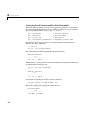
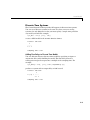
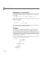
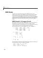
1
Control System Toolbox For Use with MATLAB ® Getting Started Version 6 How to Contact The MathWorks: www.mathworks.com comp.soft-sys.matlab Web Newsgroup [email protected] Technical support Product enhancement suggestions Bug reports Documentation error reports Order status, license renewals, passcodes Sales, pricing, and general information 508-647-7000 Phone 508-647-7001 Fax The MathWorks, Inc. 3 Apple Hill Drive Natick, MA 01760-2098 Mail [email protected] [email protected] [email protected] [email protected] [email protected] For contact information about worldwide offices, see the MathWorks Web site. Getting Started with the Control System Toolbox COPYRIGHT 2000 - 2004 by The MathWorks, Inc. The software described in this document is furnished under a license agreement. The software may be used or copied only under the terms of the license agreement. No part of this manual may be photocopied or reproduced in any form without prior written consent from The MathWorks, Inc. FEDERAL ACQUISITION: This provision applies to all acquisitions of the Program and Documentation by, for, or through the federal government of the United States. By accepting delivery of the Program or Documentation, the government hereby agrees that this software or documentation qualifies as commercial computer software or commercial computer software documentation as such terms are used or defined in FAR 12.212, DFARS Part 227.72, and DFARS 252.227-7014. Accordingly, the terms and conditions of this Agreement and only those rights specified in this Agreement, shall pertain to and govern the use, modification, reproduction, release, performance, display, and disclosure of the Program and Documentation by the federal government (or other entity acquiring for or through the federal government) and shall supersede any conflicting contractual terms or conditions. If this License fails to meet the government's needs or is inconsistent in any respect with federal procurement law, the government agrees to return the Program and Documentation, unused, to The MathWorks, Inc. MATLAB, Simulink, Stateflow, Handle Graphics, and Real-Time Workshop are registered trademarks, and TargetBox is a trademark of The MathWorks, Inc. Other product or brand names are trademarks or registered trademarks of their respective holders. Printing History: November 2000 June 2001 July 2002 June 2004 First printing Second printing Online only Online only New for Version 5 (Release 12) Revised for Version 5.1 (Release 12.1) Revised for Version 5.2 (Release 13) Revised for Version 6.0 (Release 14) Contents Introduction 1 What Is the Control System Toolbox? . . . . . . . . . . . . . . . . . . . 1-2 Installation . . . . . . . . . . . . . . . . . . . . . . . . . . . . . . . . . . . . . . . . . . . 1-3 Demos . . . . . . . . . . . . . . . . . . . . . . . . . . . . . . . . . . . . . . . . . . . . . . . 1-4 Using the Documentation . . . . . . . . . . . . . . . . . . . . . . . . . . . . . . 1-5 Building Models 2 Linear Models . . . . . . . . . . . . . . . . . . . . . . . . . . . . . . . . . . . . . . . . 2-2 Linear Model Representations . . . . . . . . . . . . . . . . . . . . . . . . . . 2-2 SISO Example: the DC Motor . . . . . . . . . . . . . . . . . . . . . . . . . . . 2-3 Constructing SISO Models . . . . . . . . . . . . . . . . . . . . . . . . . . . . . 2-5 Discrete Time Systems . . . . . . . . . . . . . . . . . . . . . . . . . . . . . . . . 2-9 Adding Delays to Linear Models . . . . . . . . . . . . . . . . . . . . . . . . 2-10 LTI Objects . . . . . . . . . . . . . . . . . . . . . . . . . . . . . . . . . . . . . . . . 2-10 MIMO Models . . . . . . . . . . . . . . . . . . . . . . . . . . . . . . . . . . . . . . . MIMO Example: Jet Transport Aircraft . . . . . . . . . . . . . . . . . Constructing MIMO Transfer Functions . . . . . . . . . . . . . . . . . Accessing I/O Pairs in MIMO Systems . . . . . . . . . . . . . . . . . . 2-12 2-12 2-14 2-16 Arrays of Linear Models . . . . . . . . . . . . . . . . . . . . . . . . . . . . . . 2-17 Model Characteristics . . . . . . . . . . . . . . . . . . . . . . . . . . . . . . . . 2-20 Interconnecting Linear Models . . . . . . . . . . . . . . . . . . . . . . . 2-21 Feedback Interconnection . . . . . . . . . . . . . . . . . . . . . . . . . . . . . 2-22 i Continuous/Discrete Conversions . . . . . . . . . . . . . . . . . . . . . 2-23 Discrete DC Motor Model . . . . . . . . . . . . . . . . . . . . . . . . . . . . . 2-23 Model Order Reduction . . . . . . . . . . . . . . . . . . . . . . . . . . . . . . . 2-25 Example: Gasifier Model . . . . . . . . . . . . . . . . . . . . . . . . . . . . . . 2-25 Analyzing Models 3 LTI Viewer . . . . . . . . . . . . . . . . . . . . . . . . . . . . . . . . . . . . . . . . . . . 3-2 Example: Time and Frequency Responses of the DC Motor . . . . . . . . . . . . . . . . . . . . . . . . . . . . . . . . . . . . . . 3-3 Right-Click Menus . . . . . . . . . . . . . . . . . . . . . . . . . . . . . . . . . . . . 3-5 Displaying Response Characteristics on a Plot . . . . . . . . . . . . . 3-6 Changing Plot Type . . . . . . . . . . . . . . . . . . . . . . . . . . . . . . . . . . 3-10 Showing Multiple Response Types . . . . . . . . . . . . . . . . . . . . . . 3-12 Comparing Multiple Models . . . . . . . . . . . . . . . . . . . . . . . . . . . 3-13 Functions for Time and Frequency Response . . . . . . . . . . . Time and Frequency Responses . . . . . . . . . . . . . . . . . . . . . . . . Plotting MIMO Model Responses . . . . . . . . . . . . . . . . . . . . . . . Data Markers . . . . . . . . . . . . . . . . . . . . . . . . . . . . . . . . . . . . . . . Plotting and Comparing Multiple Systems . . . . . . . . . . . . . . . Creating Custom Plots . . . . . . . . . . . . . . . . . . . . . . . . . . . . . . . . 3-17 3-17 3-19 3-22 3-24 3-26 Designing Compensators 4 The SISO Design Tool . . . . . . . . . . . . . . . . . . . . . . . . . . . . . . . . . Opening the SISO Design Tool . . . . . . . . . . . . . . . . . . . . . . . . . . Importing Models into the SISO Design Tool . . . . . . . . . . . . . . . Feedback Structure . . . . . . . . . . . . . . . . . . . . . . . . . . . . . . . . . . . Loop Responses . . . . . . . . . . . . . . . . . . . . . . . . . . . . . . . . . . . . . . ii Contents 4-2 4-2 4-4 4-5 4-7 Bode Diagram Design . . . . . . . . . . . . . . . . . . . . . . . . . . . . . . . . . 4-9 Example: DC Motor . . . . . . . . . . . . . . . . . . . . . . . . . . . . . . . . . . . 4-9 Adjusting the Compensator Gain . . . . . . . . . . . . . . . . . . . . . . . . 4-9 Right-Click Menus . . . . . . . . . . . . . . . . . . . . . . . . . . . . . . . . . . . 4-10 Adjusting the Bandwidth . . . . . . . . . . . . . . . . . . . . . . . . . . . . . . 4-11 Adding an Integrator . . . . . . . . . . . . . . . . . . . . . . . . . . . . . . . . . 4-13 Adding a Lead Network . . . . . . . . . . . . . . . . . . . . . . . . . . . . . . . 4-16 Moving Compensator Poles and Zeros . . . . . . . . . . . . . . . . . . . 4-18 Changing Units on a Plot . . . . . . . . . . . . . . . . . . . . . . . . . . . . . 4-21 Adding a Notch Filter . . . . . . . . . . . . . . . . . . . . . . . . . . . . . . . . 4-22 Adding a Prefilter . . . . . . . . . . . . . . . . . . . . . . . . . . . . . . . . . . . . 4-24 Converting Between Continuous and Discrete Time . . . . . . . . 4-28 Root Locus Design . . . . . . . . . . . . . . . . . . . . . . . . . . . . . . . . . . . Example: Electrohydraulic Servomechanism . . . . . . . . . . . . . . Changing the Compensator Gain . . . . . . . . . . . . . . . . . . . . . . . Adding Poles and Zeros to the Compensator . . . . . . . . . . . . . . Editing Compensator Pole and Zero Locations . . . . . . . . . . . . Viewing Damping Ratios . . . . . . . . . . . . . . . . . . . . . . . . . . . . . . Exporting the Compensator and Models . . . . . . . . . . . . . . . . . Storing and Retrieving Intermediate Designs . . . . . . . . . . . . . 4-29 4-30 4-35 4-36 4-40 4-42 4-45 4-46 Nichols Plot Design . . . . . . . . . . . . . . . . . . . . . . . . . . . . . . . . . . DC Motor Example . . . . . . . . . . . . . . . . . . . . . . . . . . . . . . . . . . Opening a Nichols Plot . . . . . . . . . . . . . . . . . . . . . . . . . . . . . . . Adjusting the Compensator Gain . . . . . . . . . . . . . . . . . . . . . . . Adding an Integrator . . . . . . . . . . . . . . . . . . . . . . . . . . . . . . . . . Adding a Lead Network . . . . . . . . . . . . . . . . . . . . . . . . . . . . . . . 4-48 4-48 4-49 4-50 4-52 4-53 Functions for Compensator Design . . . . . . . . . . . . . . . . . . . . 4-57 Root Locus Design . . . . . . . . . . . . . . . . . . . . . . . . . . . . . . . . . . . 4-57 Pole Placement . . . . . . . . . . . . . . . . . . . . . . . . . . . . . . . . . . . . . . 4-57 Linear-Quadratic-Gaussian (LQG) Design . . . . . . . . . . . . . . Optimal State-Feedback Gain . . . . . . . . . . . . . . . . . . . . . . . . . . Kalman State Estimator . . . . . . . . . . . . . . . . . . . . . . . . . . . . . . LQG Regulator . . . . . . . . . . . . . . . . . . . . . . . . . . . . . . . . . . . . . . LQG Design Tools . . . . . . . . . . . . . . . . . . . . . . . . . . . . . . . . . . . Example: LQG Design . . . . . . . . . . . . . . . . . . . . . . . . . . . . . . . . Example: LQG Design for Set Point Tracking . . . . . . . . . . . . . 4-61 4-62 4-63 4-65 4-65 4-66 4-69 iii Learning More 5 Demos . . . . . . . . . . . . . . . . . . . . . . . . . . . . . . . . . . . . . . . . . . . . . . Online Help . . . . . . . . . . . . . . . . . . . . . . . . . . . . . . . . . . . . . . . . . Setting Plot Preferences and Properties . . . . . . . . . . . . . . . . . . . The MathWorks Online . . . . . . . . . . . . . . . . . . . . . . . . . . . . . . . . 5-2 5-2 5-2 5-4 Index iv Contents 1 Introduction What Is the Control System Toolbox? (p. 1-2) A brief overview of the Control System Toolbox functionality Installation (p. 1-3) How to install the Control System Toolbox Demos (p. 1-4) Where to find Control System Toolbox demos Using the Documentation (p. 1-5) How to find the information you need in this documentation set 1 Introduction What Is the Control System Toolbox? MATLAB® has a rich collection of functions immediately useful to the control engineer or system theorist. Complex arithmetic, eigenvalues, root-finding, matrix inversion, and fast Fourier transforms are just a few examples of important numerical tools found in MATLAB. More generally, the MATLAB linear algebra, matrix computation, and numerical analysis capabilities provide a reliable foundation for control system engineering as well as many other disciplines. The Control System Toolbox builds on the foundations of MATLAB to provide functions designed for control engineering. The Control System Toolbox is a collection of algorithms, written mostly as M-files, that implements common control system design, analysis, and modeling techniques. Convenient graphical user interfaces (GUIs) simplify typical control engineering tasks. Control systems can be modeled as transfer functions, in zero-pole-gain or state-space form, allowing you to use both classical and modern control techniques. You can manipulate both continuous-time and discrete-time systems. Conversions between various model representations are provided. Time responses, frequency responses, and root loci can be computed and graphed. Other functions allow pole placement, optimal control, and estimation. Finally, the Control System Toolbox is open and extensible. You can create custom M-files to suit your particular application. 1-2 Installation Installation Instructions for installing the Control System Toolbox can be found in the MATLAB Installation documentation for your platform. We recommend that you store the files from this toolbox in a subdirectory named control under the main matlab directory. To determine if the Control System Toolbox is already installed on your system, check for a subdirectory named control within the main toolbox directory or folder. 1-3 1 Introduction Demos The Control System Toolbox provides demonstration files that show you how to use the toolbox to perform control design tasks in various settings. To run these demos, type demo at the MATLAB prompt. This opens the Demos pane in the Help browser. Select Toolboxes and then Control System to see a list of available demos. Alternatively, if you have the Help browser open, you can select the Demos pane directly and follow the same procedure. In addition, “Design Case Studies” in the online documentation contains detailed examples of various design problems. 1-4 Using the Documentation Using the Documentation If you are a new user, this guide, Getting Started with the Control System Toolbox, is written for you. Specifically, you will learn • How to build and manipulate linear time-invariant models of dynamical systems • How to analyze such models and plot their time and frequency responses • How to design compensators using root locus and pole placement techniques In addition, this guide discusses model order reduction, linear quadratic Gaussian (LQG) techniques, and presents examples that show how to use these techniques. This guide is available online under the Control System Toolbox. The rest of the toolbox documentation is also available online; click Control System Toolbox to open its product page, which is a roadmap with links to the Control System Toolbox documentation and to PDF versions of the same documentation. If you are an experienced toolbox user, see the online documentation for detailed discussions of control system design topics, including the following: • “Release Notes” — Details on the latest release • “Creating and Manipulating Models” — In-depth information on how to create and manipulate linear models and linear time-invariant (LTI) arrays, which are data objects that you can use to store collections of linear models in one variable • “Customization” — Information about setting plot properties, including how to set preferences that persist from session to session • “Design Case Studies” — Worked examples, including Kalman filtering and MIMO design • “Reliable Computations” — Numerical stability and accuracy issues • “GUI Reference” — Complete descriptions of the LTI Viewer and SISO Design Tool, which are graphical user interfaces (GUIs) that you can use to analyze systems and design SISO compensators All toolbox users should use the online Control System Toolbox Function Reference for reference information on functions and tools. For functions, 1-5 1 Introduction reference descriptions include a synopsis of the function’s syntax, as well as a complete explanation of options and operation. Many reference descriptions also include helpful examples, a description of the function’s algorithm, and references to additional reading material. For GUI-based tools, the descriptions include options for invoking the tool. 1-6 2 Building Models Linear Models (p. 2-2) How to build linear, time-invariant (LTI) models MIMO Models (p. 2-12) How to build multiple input/output (MIMO) LTI models Arrays of Linear Models (p. 2-17) How to create and manipulate LTI arrays, MATLAB objects that store multiple linear models in one variable Model Characteristics (p. 2-20) How to access and manipulate model properties and characteristics Interconnecting Linear Models (p. 2-21) How to build models by interconnecting models of subsystems Continuous/Discrete Conversions (p. 2-23) How to convert between continuous- and discrete-time systems, specifying sample times, and introducing time delays to your systems Model Order Reduction (p. 2-25) Reducing the number of states in a large-scale system, using a gasifier model as an example 2 Building Models Linear Models Typically, control engineers begin by developing a mathematical description of the dynamic system that they want to control. The system to be controlled is called a plant. As an example of a plant, this section uses the DC motor. This section develops the differential equations that describe the electromechanical properties of a DC motor with an inertial load. It then shows you how to use the Control System Toolbox to build linear models based on these equations. Linear Model Representations The Control System Toolbox supports the following model representations: • State-space models (SS) of the form dx- = Ax + Bu ----dt y = Cx + Du where A, B, C, and D are matrices of appropriate dimensions, x is the state vector, and u and y are the input and output vectors. • Transfer functions (TF), for example, s+2 H ( s ) = --------------------------2 s + s + 10 • Zero-pole-gain (ZPK) models, for example, (z + 1 + j )( z + 1 – j ) H ( z ) = 3 -------------------------------------------------( z + 0.2 ) ( z + 0.1 ) • Frequency response data (FRD) models, which consist of sampled measurements of a system’s frequency response. For example, you can store experimentally collected frequency response data in an FRD model. Note The design of FRD models is a specialized subject that this guide does not address. See Frequency Response Data (FRD) Models under Creating and Manipulating Models in the online documentation for a discussion of this topic. 2-2 Linear Models SISO Example: the DC Motor A simple model of a DC motor driving an inertial load shows the angular rate of the load, ω ( t ) , as the output and applied voltage, v app ( t ) , as the input. The ultimate goal of this example is to control the angular rate by varying the applied voltage. This picture shows a simple model of the DC motor. i(t) R + L vapp(t) I Load L Inertial + vemf(t) - - DC Motor Kfω(t) Viscous friction Load J τ(t) Torque ω(t) Angular rate A Simple Model of a DC Motor Driving an Inertial Load In this model, the dynamics of the motor itself are idealized; for instance, the magnetic field is assumed to be constant. The resistance of the circuit is denoted by R and the self-inductance of the armature by L. If you are unfamiliar with the basics of DC motor modeling, consult any basic text on physical modeling. The important thing here is that with this simple model and basic laws of physics, it is possible to develop differential equations that describe the behavior of this electromechanical system. In this example, the relationships between electric potential and mechanical force are Faraday’s law of induction and Ampère’s law for the force on a conductor moving through a magnetic field. Mathematical Derivation The torque τ seen at the shaft of the motor is proportional to the current i induced by the applied voltage, τ ( t ) = Km i ( t ) 2-3 2 Building Models where Km, the armature constant, is related to physical properties of the motor, such as magnetic field strength, the number of turns of wire around the conductor coil, and so on. The back (induced) electromotive force, v emf , is a voltage proportional to the angular rate ω seen at the shaft, v emf ( t ) = K b ω ( t ) where Kb, the emf constant, also depends on certain physical properties of the motor. The mechanical part of the motor equations is derived using Newton’s law, which states that the inertial load J times the derivative of angular rate equals the sum of all the torques about the motor shaft. The result is this equation, J dω = dt ∑ τi = – Kf ω ( t ) + Km i ( t ) where K f ω is a linear approximation for viscous friction. Finally, the electrical part of the motor equations can be described by v app ( t ) – v emf ( t ) = L di + Ri ( t ) dt or, solving for the applied voltage and substituting for the back emf, v app ( t ) = L di + Ri ( t ) + K b ω ( t ) dt This sequence of equations leads to a set of two differential equations that describe the behavior of the motor, the first for the induced current, Kb R 1 di = – ---- i ( t ) – ------- ω ( t ) + ---- v app ( t ) L L L dt and the second for the resulting angular rate, 1 1 dω = – --- K f ω ( t ) + --- K m i ( t ) J J dt 2-4 Linear Models State-Space Equations for the DC Motor Given the two differential equations derived in the last section, you can now develop a state-space representation of the DC motor as a dynamic system. The current i and the angular rate ω are the two states of the system. The applied voltage, v app , is the input to the system, and the angular velocity ω is the output. R K – ---- – ------b1 d i L L ⋅ i + ---- ⋅ v = L app ( t ) dt ω Km Kf ω 0 -------- – -----J J y ( t ) = 0 1 ⋅ i + [ 0 ] ⋅ v app ( t ) ω State-Space Representation of the DC Motor Example Constructing SISO Models Once you have a set of differential equations that describe your plant, you can construct SISO models using simple commands in the Control System Toolbox. The following sections discuss • Constructing a state-space model of the DC motor • Converting between model representations • Creating transfer function and zero/pole/gain models Constructing a State-Space Model of the DC Motor Listed below are nominal values for the various parameters of a DC motor. R= L= Km Kb Kf J= 2.0 % Ohms 0.5 % Henrys = .015 % torque constant = .015 % emf constant = 0.2 % Nms 0.02 % kg.m^2/s^2 Given these values, you can construct the numerical state-space representation using the ss function. 2-5 2 Building Models A = [-R/L -Kb/L; Km/J -Kf/J] B = [1/L; 0]; C = [0 1]; D = [0]; sys_dc = ss(A,B,C,D) This is the output of the last command. a = x1 x2 x1 -4 0.75 x1 x2 u1 2 0 y1 x1 0 y1 u1 0 x2 -0.03 -10 b = c = x2 1 d = Converting Between Model Representations Now that you have a state-space representation of the DC motor, you can convert to other model representations, including transfer function (TF) and zero/pole/gain (ZPK) models. Transfer Function Representation. You can use tf to convert from the state-space representation to the transfer function. For example, use this code to convert to the transfer function representation of the DC motor. sys_tf = tf(sys_dc) 2-6 Linear Models Transfer function: 1.5 -----------------s^2 + 14 s + 40.02 Zero/Pole/Gain Representation. Similarly, the zpk function converts from state-space or transfer function representations to the zero/pole/gain format. Use this code to convert from the state-space representation to the zero/pole/gain form for the DC motor. sys_zpk = zpk(sys_dc) Zero/pole/gain: 1.5 ------------------(s+4.004) (s+9.996) Note The state-space representation is best suited for numerical computations. For highest accuracy, convert to state space prior to combining models and avoid the transfer function and zero/pole/gain representations, except for model specification and inspection. See “Reliable Computations” in the online Control System Toolbox documentation for more information on numerical issues. 2-7 2 Building Models Constructing Transfer Function and Zero/Pole/Gain Models In the DC motor example, the state-space approach produces a set of matrices that represents the model. If you choose a different approach, you can construct the corresponding models using tf, zpk, ss, or frd. sys sys sys sys = = = = tf(num,den) zpk(z,p,k) ss(a,b,c,d) frd(response,frequencies) % % % % Transfer function Zero/pole/gain State-space Frequency response data For example, if you want to create the transfer function of the DC motor directly, use these commands. s = tf('s'); sys_tf = 1.5/(s^2+14*s+40.02) The Control System Toolbox builds this transfer function. Transfer function: 1.5 -------------------s^2 + 14 s + 40.02 Alternatively, you can create the transfer function by specifying the numerator and denominator with this code. sys_tf = tf(1.5,[1 14 40.02]) Transfer function: 1.5 -----------------s^2 + 14 s + 40.02 To build the zero/pole/gain model, use this command. sys_zpk = zpk([],[-9.996 -4.004], 1.5) This is the resulting zero/pole/gain representation. Zero/pole/gain: 1.5 ------------------(s+9.996) (s+4.004) 2-8 Linear Models Discrete Time Systems The Control System Toolbox provides full support for discrete-time systems. You can create discrete systems in the same way that you create analog systems; the only difference is that you must specify a sample time period for any model you build. For example, sys_disc = tf(1, [1 1], .01); creates a SISO model in the transfer function format. Transfer function: 1 ----z + 1 Sampling time: 0.01 Adding Time Delays to Discrete-Time Models You can add time delays to discrete-time models by specifying an input or output time delay when building the model. The time delay must be a nonnegative integer that represents a multiple of the sampling time. For example, sys_delay = tf(1, [1 1], 0.01,'outputdelay',5); produces a system with an output delay of 0.05 second. Transfer function: 1 z^(-5) * ----z + 1 Sampling time: 0.01 2-9 2 Building Models Adding Delays to Linear Models You can add time delays to linear models by specifying an input or output delay when building a model. For example, to add an input delay to the DC motor, use this code. sys_tfdelay = tf(1.5, [1 14 40.02],'inputdelay',0.05) The Control System Toolbox constructs the DC motor transfer function, but adds a 0.05 second delay. Transfer function: 1.5 exp(-0.05*s) * -----------------s^2 + 14 s + 40.02 For a complete description of adding time delays to models, see “Time Delays” online under “Creating and Manipulating Models.” LTI Objects For convenience, the Control System Toolbox uses custom data structures called LTI objects to store model-related data. For example, the variable sys_dc created for the DC motor example is called an SS object. There are also TF, ZPK, and FRD objects for transfer function, zero/pole/gain, and frequency data response models respectively. The four LTI objects encapsulate the model data and enable you to manipulate linear systems as single entities rather than as collections of vectors or matrices. To see what LTI objects contain, use the get command. This code describes the contents of sys_dc from the DC motor example. get(sys_dc) a: b: c: d: e: StateName: Ts: ioDelay: InputDelay: OutputDelay: 2-10 [2x2 double] [2x1 double] [0 1] 0 [] {2x1 cell} 0 0 0 0 Linear Models InputName: OutputName: InputGroup: OutputGroup: Notes: UserData: {''} {''} {0x2 cell} {0x2 cell} {} [] You can manipulate the data contained in LTI objects using the set command; see the Control System Toolbox online reference pages for descriptions of set and get. Another convenient way to set or retrieve LTI model properties is to access them directly using dot notation. For example, if you want to access the value of the A matrix, instead of using get, you can type sys_dc.a at the MATLAB prompt. MATLAB returns the A matrix. ans = -4.0000 0.7500 -0.0300 -10.0000 Similarly, if you want to change the values of the A matrix, you can do so directly, as this code shows. A_new = [-4.5 -0.05; 0.8 -12.0]; sys_dc.a = A_new; For more information on LTI properties, type ltiprops at the MATLAB prompt. For a complete description of LTI objects, see “Creating and Manipulating Models” online under the Control System Toolbox. 2-11 2 Building Models MIMO Models You can use the same functions that apply to SISO systems to create multiple-input, multiple-output (MIMO) models, including arbitrary MIMO transfer functions and zero/pole/gain models. This section begins with an example of how to build a MIMO system. It then discusses how to build MIMO transfer functions by concatenating SISO transfer functions and how to access and manipulate individual SISO transfer functions contained in a MIMO model. MIMO Example: Jet Transport Aircraft This example shows how to build a MIMO model of a jet transport. Since the development of a physical model for a jet aircraft is lengthy, only the state-space equations are presented here. See any standard text in aviation for a more complete discussion of the physics behind aircraft flight. The jet model during cruise flight at MACH = 0.8 and H = 40,000 ft. is A = [-0.0558 0.5980 -3.0500 0 B = [ 0.0073 -0.4750 0.1530 0 C = [0 0 1 0 D = [0 0 0 0]; -0.9968 -0.1150 0.3880 0.0805 0.0802 -0.0318 -0.4650 1.0000 0.0415 0 0 0]; 0 0.0077 0.1430 0]; 0 0 0 1]; Use the following commands to specify this state-space model as an LTI object and attach names to the states, inputs, and outputs. states = {'beta' 'yaw' 'roll' 'phi'}; inputs = {'rudder' 'aileron'}; outputs = {'yaw rate' 'bank angle'}; 2-12 MIMO Models sys_mimo = ss(A,B,C,D,'statename',states,... 'inputname',inputs,... 'outputname',outputs); You can display the LTI model by typing sys_mimo. sys_mimo a = beta yaw roll phi beta -0.0558 0.598 -3.05 0 beta yaw roll phi rudder 0.0073 -0.475 0.153 0 yaw rate bank angle beta 0 0 yaw -0.9968 -0.115 0.388 0.0805 roll 0.0802 -0.0318 -0.465 1 phi 0.0415 0 0 0 roll 0 0 phi 0 1 b = aileron 0 0.0077 0.143 0 c = yaw 1 0 d = yaw rate bank angle rudder 0 0 aileron 0 0 Continuous-time model. The model has two inputs and two outputs. The units are radians for beta (sideslip angle) and phi (bank angle) and radians/sec for yaw (yaw rate) and roll (roll rate). The rudder and aileron deflections are in degrees. 2-13 2 Building Models As in the SISO case, use tf to derive the transfer function representation. tf(sys_mimo) Transfer function from input "rudder" to output... -0.475 s^3 - 0.2479 s^2 - 0.1187 s - 0.05633 yaw rate: --------------------------------------------------s^4 + 0.6358 s^3 + 0.9389 s^2 + 0.5116 s + 0.003674 0.1148 s^2 - 0.2004 s - 1.373 bank angle: --------------------------------------------------s^4 + 0.6358 s^3 + 0.9389 s^2 + 0.5116 s + 0.003674 Transfer function from input "aileron" to output... 0.0077 s^3 - 0.0005372 s^2 + 0.008688 s + 0.004523 yaw rate: --------------------------------------------------s^4 + 0.6358 s^3 + 0.9389 s^2 + 0.5116 s + 0.003674 0.1436 s^2 + 0.02737 s + 0.1104 bank angle: --------------------------------------------------s^4 + 0.6358 s^3 + 0.9389 s^2 + 0.5116 s + 0.003674 Constructing MIMO Transfer Functions MIMO transfer functions are two-dimensional arrays of elementary SISO transfer functions. There are two ways to specify MIMO transfer function models: • Concatenation of SISO transfer function models • Using tf with cell array arguments Concatenation of SISO Models Consider the following single-input, two-output transfer function. s–1 -----------s+1 H(s ) = s+2 ---------------------------2 s + 4s + 5 You can specify H ( s ) by concatenation of its SISO entries. For instance, 2-14 MIMO Models h11 = tf([1 -1],[1 1]); h21 = tf([1 2],[1 4 5]); or, equivalently, s = tf('s') h11 = (s-1)/(s+1); h21 = (s+2)/(s^2+4*s+5); can be concatenated to form H ( s ) . H = [h11; h21] This syntax mimics standard matrix concatenation and tends to be easier and more readable for MIMO systems with many inputs and/or outputs. See “Model Interconnection Functions” in “Creating and Manipulating Models” online for more details on concatenation operations for LTI systems. Using the tf Function with Cell Arrays Alternatively, to define MIMO transfer functions using tf, you need two cell arrays (say, N and D) to represent the sets of numerator and denominator polynomials, respectively. See “Structures and Cell Arrays” in the MATLAB online documentation for more details on cell arrays. For example, for the rational transfer matrix H ( s ) , the two cell arrays N and D should contain the row-vector representations of the polynomial entries of N(s) = s – 1 s+2 D( s) = s+1 s2 + 4s + 5 You can specify this MIMO transfer matrix H ( s ) by typing N = {[1 -1];[1 2]}; % Cell array for N(s) D = {[1 1];[1 4 5]}; % Cell array for D(s) H = tf(N,D) The Control System Toolbox responds with Transfer function from input to output... s - 1 #1: ----s + 1 2-15 2 Building Models #2: s + 2 ------------s^2 + 4 s + 5 Notice that both N and D have the same dimensions as H. For a general MIMO transfer matrix H ( s ) , the cell array entries N{i,j} and D{i,j} should be row-vector representations of the numerator and denominator of H ij ( s ), the ijth entry of the transfer matrix H ( s ) . Accessing I/O Pairs in MIMO Systems Once you have defined a MIMO system, you can access and manipulate I/O pairs by specifying input and output pairs of the system. For instance, if sys_mimo is a MIMO system with two inputs and three outputs, sys_mimo(3,1) extracts the subsystem, mapping the first input to the third output. Row indices select the outputs and column indices select the inputs. Similarly, sys_mimo(3,1) = tf(1,[1 0]) redefines the transfer function between the first input and third output as an integrator. 2-16 Arrays of Linear Models Arrays of Linear Models You can specify and manipulate collections of linear models as single entities using LTI arrays. For example, if you want to vary the Kb and Km parameters for the DC motor and store the resulting state-space models, use this code. K = [0.1 0.15 0.2]; % Several values for Km and Kb A1 = [-R/L -K(1)/L; K(1)/J -Kf/J]; A2 = [-R/L -K(2)/L; K(2)/J -Kf/J]; A3 = [-R/L -K(3)/L; K(3)/J -Kf/J]; sys_lti(:,:,1)= ss(A1,B,C,D); sys_lti(:,:,2)= ss(A2,B,C,D); sys_lti(:,:,3)= ss(A3,B,C,D); (Note that Kb and Km must be equal, so K represents both parameters in the state-space equations.) The number of inputs and outputs must be the same for all linear models encapsulated by the LTI array, but the model order (number of states) can vary from model to model within a single LTI array. The LTI array sys_lti contains the state-space models for each value of K. Type sys_lti to see the contents of the LTI array. Model sys_lti(:,:,1,1) ====================== a = x1 x2 x1 -4 5 x2 -0.2 -10 x1 -4 7.5 x2 -0.3 -10 . . . Model sys_lti(:,:,2,1) ====================== a = x1 x2 . . 2-17 2 Building Models . Model sys_lti(:,:,3,1) ====================== a = x1 x2 x1 -4 10 x2 -0.4 -10 . . . 3x1 array of continuous-time state-space models. You can manipulate the LTI array like any other object in the Control System Toolbox. For example, step(sys_lti) produces a plot containing step responses for all three state-space models. 2-18 Arrays of Linear Models Step Responses for an LTI Array Containing Three Models LTI arrays are useful for performing batch analysis on an entire set of models. For more information, see “Arrays of LTI Models” online under “Creating and Manipulating Models” in the Control System Toolbox. 2-19 2 Building Models Model Characteristics The Control System Toolbox contains commands to query model characteristics such as the I/O dimensions, poles, zeros, and DC gain. These commands apply to both continuous- and discrete-time models. Their LTI-based syntax is summarized in the table below. Commands to Query Model Characteristics 2-20 Command Description size(model_name) Number of inputs and outputs ndims(model_name) Number of dimensions isct(model_name) Returns 1 for continuous systems isdt(model_name) Returns 1 for discrete systems hasdelay(model_name) True if system has delays pole(model_name) System poles zero(model_name) System (transmission) zeros dcgain(model_name) DC gain norm(model_name) System norms (H2 and L∞) covar(model_name,W) Covariance of response to white noise Interconnecting Linear Models Interconnecting Linear Models You can perform simple operations on LTI models, such as addition, multiplication, or concatenation. Addition performs a parallel interconnection. For example, typing tf(1,[1 0]) + tf([1 1],[1 2]) % 1/s + (s+1)/(s+2) produces this transfer function. Transfer function: s^2 + 2 s + 2 ------------s^2 + 2 s Multiplication performs a series interconnection. For example, typing 2 * tf(1,[1 0])*tf([1 1],[1 2]) % 2*1/s*(s+1)/(s+2) produces this cascaded transfer function. Transfer function: 2 s + 2 --------s^2 + 2 s If the operands are models of different types, the resulting model type is determined by precedence rules; see “Precedence Rules” under “Creating and Manipulating Models” online for more information. State-space models have the highest precedence while transfer functions have the lowest precedence. Hence the sum of a transfer function and a state-space model is always a state-space model. Other available operations include system inversion, transposition, and pertransposition; see “Arithmetic Operations” online under “Creating and Manipulating Models.” The Control System Toolbox also supports matrix-like indexing for extracting subsystems; see “Extracting and Modifying Subsystems” online in “Operations on LTI Models” (also under “Creating and Manipulating Models”) for more information. 2-21 2 Building Models You can also use the series and parallel functions as substitutes for multiplication and addition, respectively. Equivalent Ways to Interconnect Systems Operator Function Resulting Transfer Function sys1 + sys2 parallel(sys1,sys2) Systems in parallel sys1 * sys2 series(sys2,sys1) Cascaded systems Feedback Interconnection You can use the feedback and lft functions to derive closed-loop models. For example, sys_f = feedback(tf(1,[1 0]), tf([1 1],[1 2]) computes the closed-loop transfer function from r to y for the feedback loop shown below. The result is Transfer function: s + 2 ------------s^2 + 3 s + 1 This figure shows the interconnected system in block diagram format. r + Σ − 1 --s y s+1 -----------s+2 Feedback Interconnection You can use the lft function to create more complicated feedback structures. This function constructs the linear fractional transformation of two systems. See the online reference page for more information. 2-22 Continuous/Discrete Conversions Continuous/Discrete Conversions The commands c2d, d2c, and d2d perform continuous to discrete, discrete to continuous, and discrete to discrete (resampling) conversions, respectively. sysd = c2d(sysc,Ts) sysc = d2c(sysd) sysd1= d2d(sysd,Ts) % Discretization w/ sample period Ts % Equivalent continuous-time model % Resampling at the period Ts Various discretization/interpolation methods are available, including zero-order hold (default), first-order hold, Tustin approximation with or without prewarping, and matched zero-pole. For example, sysd = c2d(sysc,Ts,'foh') sysc = d2c(sysd,'tustin') % Uses first-order hold % Uses Tustin approximation Discrete DC Motor Model You can digitize the DC motor plant using the c2d function and selecting an appropriate sample time. Choosing the right sample time involves many factors, including the performance you want to achieve, the fastest time constant in your system, and the speed at which you expect your controller to run. For this example, choose a time constant of 0.01 second. See “SISO Example: the DC Motor” on page 2-3 for the construction of the SS object sys_dc. Ts=0.01; sysd=c2d(sys_dc,Ts) a = x1 x2 x1 0.96079 0.006994 x1 x2 u1 0.019605 7.1595e-005 x2 -0.00027976 0.90484 b = 2-23 2 Building Models c = y1 x1 0 y1 u1 0 x2 1 d = Sampling time: 0.01 Discrete-time model. To see the discrete-time transfer function for the digital DC motor, use tf to convert the model. fd=tf(sysd) Transfer function: 7.16e-005 z + 6.833e-005 -----------------------z^2 - 1.866 z + 0.8694 Sampling time: 0.01 2-24 Model Order Reduction Model Order Reduction You can derive reduced-order models with the following commands. Model Order Reduction balreal Input/output balancing minreal Minimal realization (pole/zero cancellation) modred State deletion in I/O balanced realization sminreal Structurally minimal realization Use minreal to delete uncontrollable or unobservable state dynamics in state-space models, or to cancel pole/zero pairs in transfer functions or zero-pole-gain models. Use sminreal to remove any states that are structurally decoupled from the inputs or outputs. For already minimal models, you can further reduce the model order using a combination of balreal and modred. Example: Gasifier Model This example presents a model of a gasifier, a device that converts solid materials into gases. The original model is nonlinear. To load a linearized version of the model, type load ltiexamples at the MATLAB prompt; the gasifier example is stored in the variable named gasf. If you type size(gasf) MATLAB responds with State-space model with 4 outputs, 6 inputs, and 25 states. Before attempting model order reduction, inspect the pole and zero locations by using pzmap(gasf) and then zooming in near the origin. If you don’t know how to use the zoom feature on plots, see “Zooming” on page 4-33 for an example. 2-25 2 Building Models This figure shows the results. Pole-Zero Map of the Gasifier Model (Zoomed In) Since the model displays near pole-zero cancellations, it is a good candidate for model reduction. SISO Model Order Reduction As an illustration of the model order reduction tools, this example focuses on a single input/output pair of the gasifier, input 5 to output 3. sys35 = gasf(3,5); To enhance the numerical stability, first scale the system realization with ssbal. sys1 = ssbal(sys35); 2-26 Model Order Reduction Then use minreal to eliminate uncontrollable or unobservable states. sys1 = minreal(sys1); size(sys1) MATLAB responds with State-space model with 1 output, 1 input, and 15 states. The result is a 15th order system. Use this command bode(sys35,sys1); to compare the Bode magnitude and phase of the 25th order model to the reduced-order model. This figure shows the result. Comparison of Full 25-State Model to the 15-State Reduced Order Models As the figure shows, there is very little difference in the responses. 2-27 2 Building Models Finally, try eliminating states that are weakly affecting the I/O map by using the balreal and modred functions. First, attempt a balanced realization. [sys1,G] = balreal(sys1); Use format short e to view the Hankel singular values stored in variable G. G = 4.5468e+003 2.6009e+003 1.8601e+003 2.5140e+002 1.5081e+002 1.1993e+001 1.1524e+001 1.0940e+001 2.8766e+000 1.3706e+000 3.5426e-001 2.2556e-002 1.2496e-002 1.0725e-002 6.2703e-005 Small Hankel singular values indicate that the associated states are weakly coupled. You can try discarding the last five states (associated with the five smallest Hankel singular values). sys2 = modred(sys1,11:15); size(sys2) % Down to 10 states MATLAB responds with State-space model with 1 output, 1 input, and 10 states. Type bode(sys35,sys2); to compare the magnitude and phase of the 10th order model to the 25th order model. 2-28 Model Order Reduction This figure shows the result. Comparison of 25- and 10-State Models The figure shows good agreement until the frequency reaches 5 rad/s. This may be acceptable since gasifiers are often low bandwidth systems, and since the models still agree at smaller frequencies. Try experimenting with discarding more Hankel values. With each further reduction, the match to the 25th order model will continue to degrade. MIMO Model Order Reduction You can choose not to restrict yourself to individual input/output pairs. The following code does model order reduction on the full MIMO gasifier model. sys1 = ssbal(gasf) % Scaling % Compute the minimal realization and balance the model sys2 = minreal(sys1); % Down to 17 states [sys3,G] = balreal(sys2); 2-29 2 Building Models % Discard smallest entry of G by using modred sys3 = modred(sys3,17); % Down to 16 states After you get to 16 states, the reduced-order MIMO model begins to deteriorate when compared to the full 25-state MIMO model. Try reducing the model further to see which channels suffer the most degradation. Acknowledgment The MathWorks would like to thank ALSTOM Power UK for kindly permitting us to use their gasifier model for this example. This model was issued as part of the ALSTOM Benchmark Challenge on Gasifier Control. For more details see Dixon, R., (1999), “Advanced Gasifier Control,” Computing & Control Engineering Journal, IEE, Vol. 10, No. 3, pp. 92-96. 2-30 3 Analyzing Models LTI Viewer (p. 3-2) How to use the LTI Viewer, a graphical user interface (GUI) that simplifies the analysis of linear, time-invariant systems Functions for Time and Frequency Response (p. 3-17) Plotting time and frequency responses of linear models. You can use these commands when you need more flexibility than the LTI Viewer provides. 3 Analyzing Models LTI Viewer The LTI Viewer is a GUI for viewing and manipulating the response plots of linear models. You can display the following plot types for linear models using the LTI Viewer: • Step and impulse responses • Bode and Nyquist plots • Nichols plots • Singular values of the frequency response • Pole/zero plots • Response to a general input signal • Unforced response starting from given initial states (only for state-space models) Note that time responses and pole/zero plots are available only for transfer function, state-space, and zero/pole/gain models. Note The LTI Viewer displays up to six different plot types simultaneously. You can also analyze the response plots of several linear models at once. 3-2 LTI Viewer This figure shows an LTI Viewer with two response plots. Use the File menu to import models and the Edit menu to delete existing ones. Click these icons to open a new viewer, print, and zoom in and out, respectively. Right-click anywhere in a plot region to open a menu of options for that plot. Left-click directly on a curve for information about the curve at that particular point. The LTI Viewer with Step and Impulse Response Plots The next section presents an example that shows you how to import a system into the LTI Viewer and how to customize the viewer to fit your requirements. Example: Time and Frequency Responses of the DC Motor The section titled “SISO Example: the DC Motor” on page 2-3 presents a DC motor example. If you have not yet built that example, type load ltiexamples at the MATLAB prompt. This loads several LTI models, including a state-space representation of the DC motor called sys_dc. 3-3 3 Analyzing Models Opening the LTI Viewer To open the LTI Viewer, type ltiview This opens an LTI Viewer with an empty step response plot window by default. Importing Models into the LTI Viewer To import the DC motor model, select Import under the File menu. This opens the Import System Data window, which lists all the models available in your MATLAB workspace. The Import System Data Window with the DC Motor Model Selected Select sys_dc from the list of available models and click OK to close the browser. This imports the DC motor model into the LTI Viewer. To select more than one model at a time, do the following: • To select individual (noncontiguous) models, select one model and hold down the Ctrl key while selecting additional models. To clear any models, hold down the Ctrl key while you click the highlighted model names. • To select a list of contiguous models, select the first model and hold down the Shift key while selecting the last model you want in the list. 3-4 LTI Viewer The figure below shows the LTI Viewer with a step response for the DC motor example. This dashed line shows the steady-state value of the step response The status bar describes the last action you have taken. It also provides information about accessing LTI Viewer menu options. Step Response for the DC Motor Example in the LTI Viewer Alternatively, you can open the LTI Viewer and import the DC motor example directly from the MATLAB prompt. ltiview('step', sys_dc) See the ltiview reference page for a complete list of options. Right-Click Menus The LTI Viewer provides a set of controls and options that you can access by right-clicking your mouse. Once you have imported a model into the LTI Viewer, the options you can select include • Plot Type — Change the plot type. Available types include step, impulse, Bode, Bode magnitude, Nichols, Nyquist, and singular values plots. 3-5 3 Analyzing Models • Systems — Select or clear any models that you included when you created the response plot. • Characteristics — Add information about the plot. The characteristics available change from plot to plot. For example, Bode plots have stability margins available, but step responses have rise time and steady-state values available. • Grid — Add grids to your plots. • Normalize — Scale responses to fit the view (only available for time-domain plot types). • Full View — Use automatic limits to make the entire curve visible. • Properties — Open the Property Editor. You can use this editor to customize various attributes of your plot. See “Customizing Plot Properties and Preferences” online under “Customization” for a full description of the Property Editor. Alternatively, you can open the Property Editor by double-clicking in an empty region of the response plot. Displaying Response Characteristics on a Plot For example, to see the rise time for the DC motor step response, right-click your mouse and select Rise Time under Characteristics, as this figure illustrates. 3-6 LTI Viewer Using Right-Click Menus to Display the Rise Time for a Step Response The rise time is defined as the amount of time it takes the step response to go from 10% to 90% of the steady-state value. 3-7 3 Analyzing Models The LTI Viewer calculates and displays the rise time for the step response. The dot marks the 90% value for the rise time. This line shows when the response reaches 10% of its steady-state value. This line shows when the response reaches 90% of its steady-state value. DC Motor Step Response with the Rise Time Displayed To display the values of any plot characteristic marked on a plot, place your mouse on the blue dot that marks the characteristic. This opens a data marker with the relevant information displayed. To make the marker persistent, left-click the blue dot. 3-8 LTI Viewer For example, this figure shows the rise time value for the DC motor step response. Place your cursor over the blue dot to display a data marker with the system name and the 90% rise time value. Left-click the blue dot to make the data marker persistent. Using Your Mouse to Get the Rise Time Values Note that you can left-click anywhere on a particular plot line to see the response values of that plot at that point. You must either place your cursor over the blue dot or left-click, however, if you want to see the rise time value. For more information about data markers, see “Data Markers” on page 3-22. 3-9 3 Analyzing Models Changing Plot Type You can view other plots using the right-click menus in the LTI Viewer. For example, if you want to see the open loop Bode plots for the DC motor model, select Plot Type and then Bode from the right-click menu. Changing the Step Response to a Bode Plot 3-10 LTI Viewer Selecting Bode changes the step response to a Bode plot for the DC motor model. Bode Plot for the DC Motor Model 3-11 3 Analyzing Models Showing Multiple Response Types If you want to see, for example, both a step response and a Bode plot at the same time, you have to reconfigure the LTI Viewer. To view different response types in a single LTI Viewer, select Plot Configurations under the Edit menu. This opens the Plot Configurations dialog box. Select Response type for each pane in the selected arrangement. Using the Plot Configurations Dialog Box to Reconfigure the LTI Viewer You can select up to six plots in one viewer. Choose the Response type for each plot area from the right side menus. There are nine available plot types: • Step • Impulse • Bode (magnitude and phase) • Bode Magnitude (only) • Nyquist • Nichols • Sigma • Pole/Zero • I/O pole/zero 3-12 LTI Viewer Comparing Multiple Models This section shows you how to import and manipulate multiple models in one LTI Viewer. For example, if you have designed a set of compensators to control a system, you can compare the closed-loop step responses and Bode plots using the LTI Viewer. A sample set of closed-loop transfer function models is included (along with some other models) in the MAT-file ltiexamples.mat. Type load ltiexamples to load the provided transfer functions. The three closed-loop transfer function models, Gcl1, Gcl2, and Gcl3, are for a satellite attitude controller. In this example, you analyze the response plots of the Gcl1 and Gcl2 transfer functions. Initializing the LTI Viewer with Multiple Plots To load the two models Gcl1 and Gcl2 into the LTI Viewer, select Import under the File menu and select the desired models in the LTI Browser. See “Importing Models into the LTI Viewer” on page 3-4 for a description of how to select groups of models. If necessary, you can reconfigure the viewer to display both the step responses and the Bode plots of the two systems using the Viewer Configuration dialog box. See “Showing Multiple Response Types” on page 3-12 for a discussion of this feature. Alternatively, you can open an LTI Viewer with both systems and both the step responses and Bode plots displayed. To do this, type ltiview({'step';'bode'},Gcl1,Gcl2) 3-13 3 Analyzing Models Either approach opens the following LTI Viewer. Place your cursor on a curve to see which system it represents. The information is displayed in the status panel at the bottom of the LTI Viewer. Two response curves are plotted on each plot region. Multiple Response Plots in a Single LTI Viewer Inspecting Response Characteristics To mark the settling time on the step responses presented in this example, do the following: • Right-click anywhere in the plot region of the step response plots. This opens the right-click menu list in the plot region. • Place your mouse pointer on the Characteristics menu item, and select Settling Time with your left mouse button. To mark the stability margins of the Bode plot in this example, open the right-click menu and select Stability Margins (Minimum Crossing) under the Characteristics menu item. 3-14 LTI Viewer Your LTI Viewer should now look like this. Place your cursor on the blue or green dots to see phase margin data. Multiple Plots with Response Characteristics Added The minimum stability margins, meaning the smallest magnitude phase and gain margins, are displayed as green and blue markers on the Bode phase diagram. If you want to see all the gain and phase margins of a system, select Stability Margins (All Crossings) under the Characteristics menu item. 3-15 3 Analyzing Models Toggling Model Visibility If you have imported more than one model, you can select and clear the models to plot in the LTI Viewer using right-click menus. For example, if you import the following three models into the viewer, you can choose to view any combination of the three you want. s=tf('s'); sys1=1/(s^2+s+1); sys2=1/(s^2+s+2); sys3=1/(s^2+s+3); This figure shows how to clear the second of the three models using right-click menu options. Select/clear the systems you want to add or remove from the LTI Viewer under Systems in the right-click menu. The menu lists only systems that you have imported into the LTI Viewer. Using Right-Click Menus to Select/Clear Plotted Systems The Systems menu lists all the imported models. A system is selected if a check mark is visible to the left of the system name. 3-16 Functions for Time and Frequency Response Functions for Time and Frequency Response The Control System Toolbox provides the LTI Viewer, a GUI that is suitable for a wide range of applications. There are situations, however, where you may want a more open and extensible environment. The Control System Toolbox provides a set of functions that provide the basic time and frequency domain analysis plots used in control system engineering. These functions apply to any kind of linear model (continuous or discrete, SISO or MIMO, or arrays of models). You can only apply the frequency domain analysis functions to FRD models. Use the LTI Viewer when a GUI-driven environment is desirable. On the other hand, use functions when you want customized plots. If you want to include data unrelated to your models, you must use functions instead of the LTI Viewer (which only plots model data). The next sections discuss time and frequency response functions and how to use these functions to create customized plots of linear model responses. Time and Frequency Responses Time responses investigate the time-domain transient behavior of linear models for particular classes of inputs and disturbances. You can determine such system characteristics as rise time, settling time, overshoot, and steady-state error from the time response. The Control System Toolbox provides functions for step response, impulse response, initial condition response, and general linear simulations. For example, you can simulate the response to white noise inputs using lsim and the MATLAB function randn. In addition to time-domain analysis, the Control System Toolbox provides functions for frequency-domain analysis using the following standard plots: • Bode • Nichols • Nyquist • Singular value 3-17 3 Analyzing Models This table lists available time and frequency response functions and their use. Functions for Frequency and Time Response Functions Description bode Bode plot evalfr Computes the frequency response at a single complex frequency (not for FRD models) freqresp Computes the frequency response for a set of frequencies gensig Input signal generator (for lsim) impulse Impulse response plot initial Initial condition response plot iopzmap Pole-zero map for each I/O pair of an LTI model lsim Simulation of response to arbitrary inputs margin Computes and plots gain and phase margins nichols Nichols plot nyquist Nyquist plot pzmap Pole-zero map step Step response plot These functions can be applied to single linear models or LTI arrays. The functions step, impulse, and initial automatically generate an appropriate simulation horizon for the time response plots. Their syntax is step(model_name) impulse(model_name) initial(model_name,x0) % x0 = initial state vector where model_name is any continuous or discrete LTI model or LTI array. 3-18 Functions for Time and Frequency Response Frequency-domain plots automatically generate an appropriate frequency range as well. Plotting MIMO Model Responses For MIMO models, time and frequency response functions produce an array of plots with one plot per I/O channel (or per output for initial and lsim). For example, h = [tf(10,[1 2 10]) , tf(1,[1 1])] step(h) produces the following plot. Step Responses for a MIMO Model The simulation horizon is automatically determined based on the model dynamics. You can override this automatic mode by specifying a final time, step(h,10) % Simulates from 0 to 10 seconds 3-19 3 Analyzing Models or a vector of evenly spaced time samples. t = 0:0.01:10 step(h,t) % Time samples spaced every 0.01 second Right-Click Menus All the time and frequency response functions provide right-click menus that allow you to customize your plots. This figure shows the plots from the figure titled “Step Responses for a MIMO Model” on page 3-19, with the right-click menu open. Using the Right-Click Menu in a Step Response Plot The options you can select include • Systems — Select or clear any models that you included when you created the response plot. • Characteristics — Add information about the plot. The characteristics available change from plot to plot. For example, Bode plots have stability 3-20 Functions for Time and Frequency Response margins available, but step responses have rise time and steady-state values available. • Axes Grouping — Change the grouping of your plots. Available options are All, None, Inputs, and Outputs. You can group all the plots together, place each in a separate plot region (none), or group the inputs or outputs together. • I/O Selector — Open the I/O Selector window. Use this window to select/clear the inputs and outputs to plot. • Normalize — Scale responses to fit the view (only available for time-domain plot types). • Full View — Use automatic limits to make the entire curve visible. • Grid — Add grids to your plots. • Properties — Open the Property Editor, which you can use to customize various attributes of your plot. See “Customization” in the Control System Toolbox online documentation for a full description of the Property Editor. Alternatively, you can open the Property Editor by double-clicking in an empty region of the response plot. 3-21 3 Analyzing Models Data Markers In addition to right-click menus, the Control System Toolbox provides plot data markers. These allow you to identify key data points on your plots. This figure, using the same plot as in “Step Responses for a MIMO Model” on page 3-19, shows markers on the plots. Place your cursor on an active characteristic, shown as a blue dot here, to see its name and numerical value. Left-click anywhere on a plot to see the system name, I/O labels, time, and value at that point. Using Plot Markers to Identify Data Points You can move a data marker by • Grabbing the black square located at the corner of the marker • Dragging the marker with your mouse The time and amplitude values will change as you move the marker. This does not apply to markers that display plot characteristics (e.g., peak value or rise time). In the case of plot characteristic data markers, you can view them by placing your cursor over the dot that represents the active characteristic. To make the data marker persistent, left-click the marker. 3-22 Functions for Time and Frequency Response Note Data markers do not apply to the SISO Design Tool, which displays data about plot characteristics in the status panel at the bottom of the SISO Design Tool window. Right-Click Menus Right-click any data marker to open a property menu for the marker. Property options for the marker include • Alignment — Change the position of the marker. Available options are top-right, top-left, bottom-right, and bottom-left. • Font Size — Change the font size. • Movable — By default, you can move data markers by clicking and dragging. Clearing Movable forces the marker to remain at a fixed data point. • Delete — Delete the selected marker. Alternatively, left-click anywhere in the empty plot region to delete all markers in the plot. • Interpolation — By default, data markers linearly interpolate between points along the plotted curve. Select None to force the markers to snap to nearest points along the plotted curve. • Track Mode — The default is to track x- and y-values. You can choose to track only x- or y-values as well. Since characteristic data markers are by definition fixed, the right-click menus for them have fewer options. 3-23 3 Analyzing Models These options work the same as they do for the full right-click menu. Plotting and Comparing Multiple Systems You can use the command-line response-plotting functions to plot the response of continuous and discrete linear models on a single plot. To do so, invoke the corresponding command-line function using the list sys1,..., sysN of models as the inputs. step(sys1,sys2,...,sysN) impulse(sys1,sys2,...,sysN) ... bode(sys1,sys2,...,sysN) nichols(sys1,sys2,...,sysN) ... All models in the argument lists of any of the response plotting functions (except for sigma) must have the same number of inputs and outputs. To differentiate the plots easily, you can also specify a distinctive color/linestyle/marker for each system just as you would with the plot command. For example, bode(sys1,'r',sys2,'y--',sys3,'gx') plots sys1 with solid red lines, sys2 with yellow dashed lines, and sys3 with green x markers. You can plot responses of multiple models on the same plot. These models do not need to be all continuous-time or all discrete-time. Example: Comparing Continuous and Discretized Systems The following example compares a continuous model with its zero-order-hold discretization. sysc = tf(1000,[1 10 1000]) sysd = c2d(sysc,0.2) % ZOH sampled at 0.2 second step(sysc,'--',sysd,'-') 3-24 % Compare step responses Functions for Time and Frequency Response These commands produce the plot shown below. Comparison of a Continuous Model to Its Discretized Version Use this command to compare the Bode plots of the two systems. bode(sysc,'--',sysd,'-') % Compare Bode responses 3-25 3 Analyzing Models The Control System Toolbox creates this plot. Comparison of Bode Plots for a Continuous Model and Its Discretized Version A comparison of the continuous and discretized responses reveals a drastic undersampling of the continuous-time system. Specifically, there are hidden oscillations in the discretized time response and aliasing conceals the continuous-time resonance near 30 rad/s. Creating Custom Plots Time and frequency response commands are useful for creating custom plots. You can mix model response plots with other data views using response commands together with plot, subplot, and hold. Example: Custom Plots For example, the following sequence of commands displays the Bode plot, step response, pole/zero map, and some additional data in a single figure window. 3-26 Functions for Time and Frequency Response h = tf([4 8.4 30.8 60],[1 4.12 17.4 30.8 60]); subplot(221) bode(h) subplot(222) step(h) subplot(223) pzmap(h) subplot(224) plot(rand(1, 100)) % Any data can go here title('Some noise') Your plot should look similar to this illustration. Example of Model and Nonmodel Data Plotted in One Window For information about plot, subplot, hold, and other options for plotting general data, see “Basic Plots and Graphs” in the MATLAB Function Reference. These documents are available in the MATLAB online help. 3-27 3 Analyzing Models Note Each of the plots generated by response analysis functions in the preceding figure (bode, step, and pzmap) has its own right-click menu (similar to those in the LTI Viewer). To activate the right-click menus, place your mouse in the plot region and right-click. The menu contents depend on what type of plot you have selected. 3-28 4 Designing Compensators The SISO Design Tool (p. 4-2) How to use the SISO Design Tool, a graphical user interface (GUI) that simplifies the task of designing controllers. Bode Diagram Design (p. 4-9) Designing compensators using Bode diagram techniques. This section presents a DC motor example. Root Locus Design (p. 4-29) Using an electrohydraulic servomechanism example, this section discusses the design of compensators using root locus diagram techniques. Nichols Plot Design (p. 4-48) Using a DC motor example, this section discusses the design of compensators using Nichols plot techniques. Functions for Compensator Design (p. 4-57) Functions for custom applications, MIMO design, pole placement, LQG design, and Kalman filtering. This section includes several examples of these more advanced techniques. 4 Designing Compensators The SISO Design Tool The SISO Design Tool is a graphical user interface (GUI) that facilitates the design of compensators for single-input, single-output feedback loops. The SISO Design Tool allows you to iterate rapidly on your designs and perform the following tasks: • Manipulate closed-loop dynamics using root locus techniques • Shape open-loop Bode responses • Add compensator poles and zeros • Add and tune lead/lag networks and notch filters • Inspect closed-loop responses (using the LTI Viewer) • Adjust phase and gain margins • Convert models between discrete and continuous time Opening the SISO Design Tool This section shows how to open the SISO Design Tool with the DC motor example developed in Chapter 2, “Building Models.” If you have not built the DC motor model, type load ltiexamples at the MATLAB prompt. This loads a collection of linear models, including the DC motor. To open the SISO Design Tool and import the DC motor, type sisotool(sys_dc) at the MATLAB prompt. 4-2 The SISO Design Tool This command opens the SISO Design Tool with the root locus and open-loop Bode diagrams for the DC motor plotted by default. Click in the Current Compensator panel to edit the compensator. The feedback structure for design. Use the FS button to toggle between feedback structures. Right-click in any of these regions to see design and display options for the SISO Design Tool. Note that the Root Locus and Open-loop Bode Editor (C) have different sets of options. This panel displays useful tips about how to use the SISO Design Tool and information about the status of your design. SISO Design Tool with the DC Motor Example The SISO Design Tool displays • Poles as x’s • Zeros as o’s • Gain and phase margins (by default) in the lower left corners of the Bode magnitude and phase plots 4-3 4 Designing Compensators Importing Models into the SISO Design Tool If you type sisotool at the MATLAB prompt, an empty SISO Design Tool opens. You can import the DC motor model by selecting Import Model under the File menu. This opens the Import System Data dialog box, which is shown below. Place the DC motor model (sys_dc) in the field marked G (Plant). Importing the DC Motor Model into the SISO Design Tool Follow these steps to import the DC motor model: 1 Select sys_dc under SISO Models. 2 Place it into the G field under Design Model by clicking the right arrow button to the left of G. 3 Click OK. 4-4 The SISO Design Tool Feedback Structure The SISO Design Tool by default assumes that the compensator is in the forward path, i.e., that the feedback structure looks like this figure. The Default Feedback Structure — Compensator in the Forward Path In this figure, the lettered boxes represent the following: • G — Plant • H — Sensor dynamics • F — Prefilter • C — Compensator The default values for F, H, and C are all 1. Note that this means that by default, the compensator has unity gain. G contains the DC motor model sys_dc. 4-5 4 Designing Compensators Alternative Feedback Structures Clicking the FS button cycles through the default feedback structure and several other feedback structures. This figure shows the alternate feedback stuctures. Compensator in the feedback path Feedforward controller Cascade configuration with filter F in the minor loop Alternate Feedback Structures 4-6 The SISO Design Tool Loop Responses As you iterate on a compensator design, you may find it convenient to be able to examine the various loop responses (for example, step or impulse responses). For example, to view the closed-loop step response, select Other Loop Responses from the Analysis menu. This opens the Response Plot Setup window with the default setting of closed-loop step response from r, the reference signal, to y, the output signal. Click OK to open an LTI Viewer with the closed-loop step response of the DC motor. For instructions on how to operate the LTI Viewer, see “LTI Viewer” on page 3-2. 4-7 4 Designing Compensators This figure shows the resulting plot. LTI Viewer Showing the Step Response for the DC Motor As this plot shows, the step response of the DC motor is about 1.5 seconds, which is too slow for many applications. Also, there is a large steady-state error. The following sections show how to use Bode diagram techniques for improving the response time and steady-state error of the DC motor step response. As you iterate on a design, the LTI Viewer associated with your SISO Design Tool will automatically update the response plots you have chosen. 4-8 Bode Diagram Design Bode Diagram Design One technique for compensator design is to work with Bode diagrams of the open-loop response (loop shaping). Using Bode diagrams, you can design to gain and phase margin specifications, adjust the bandwidth, and add notch filters for disturbance rejection. Example: DC Motor The following sections use the DC motor example to show how to create a compensator using Bode diagram design techniques. From “SISO Example: the DC Motor” on page 2-4, the transfer function of the DC motor is Transfer function: 1.5 -----------------s^2 + 14 s + 40.02 For this example, the design criteria are as follows: • Rise time of less than 0.5 second • Steady-state error of less than 5% • Overshoot of less than 10% • Gain margin greater than 20 dB • Phase margin greater than 40 degrees Adjusting the Compensator Gain The figure titled “LTI Viewer Showing the Step Response for the DC Motor” on page 4-8 shows that the closed-loop step response is too slow. The simplest approach to speeding up the response is to increase the gain of the compensator. To increase the gain, 1 Move the mouse pointer over the Bode magnitude line. Notice how the pointer becomes a hand. 2 Grab the Bode magnitude line by holding down the left mouse button when the hand appears. 3 Drag the Bode plot line upward. 4-9 4 Designing Compensators 4 Release the mouse button. The gain and poles change as the closed-loop set point is recomputed. The SISO Design Tool calculates the compensator gain, and the value appears in the C(s) text box on the GUI. Alternatively, you can set the gain by entering the desired value in the C(s) field in the Current Compensator panel. Right-Click Menus The SISO Design Tool has right-click menus available in any of the plot regions. The menus are customized for each plot type; open the Bode magnitude menu by right-clicking your mouse in the white space of the Bode magnitude plot. This menu appears. Right-Click Menu for the Bode Magnitude Plot The right-click menus contain numerous features. The DC motor example makes use of many of the available features; for a complete discussion of the right-click menus, see the online help for the SISO Design Tool in the GUI Reference. 4-10 Bode Diagram Design Adjusting the Bandwidth Since the design requirements include a 0.5 second rise time, try setting the gain so that the DC crossover frequency is about 3 rad/s. The rationale for setting the bandwidth to 3 rad/s is that, to a first-order approximation, this should correspond to about a 0.33 second time constant. To make the crossover easier to see, select Grid from the right-click menu. This creates a grid for the Bode magnitude plot. Left-click the Bode magnitude plot and drag the curve until you see the curve crossing over the 0 dB line (on the y-axis) at 3 rad/s. This changes both the SISO Design Tool display and the LTI Viewer step response. This figure shows the SISO Design Tool. Use the hand to move the Bode magnitude plot up or down. The SISO Design Tool recalculates the compensator gain as you move the hand. Increasing the compensator gain changed the phase margin from infinity to 119°. The SISO Design Tool adds a brown stem to show the new phase margin. Root Locus and Bode Plots for the DC Motor For a crossover at 3 rad/s, the compensator gain should be about 38. 4-11 4 Designing Compensators This plot shows the associated closed-loop step response in the LTI Viewer. Closed-Loop Step Response for the DC Motor with Compensator Gain = 38 The step response shows that the steady-state error and rise time have improved somewhat, but you must design a more sophisticated controller to meet all the design specifications, in particular, the steady-state error requirement. Displaying Phase and Gain Margin By default, the SISO Design Tool displays gain and phase margin information in the lower left corners of the Bode diagrams. In the Bode magnitude plot, it also tells you if your closed-loop system is stable or unstable. 4-12 Bode Diagram Design Adding an Integrator One way to eliminate steady-state error is to add an integrator. To do this, select Add Pole/Zero and then Integrator from the right-click menu. This figure shows the process. Using the Right-Click Menu to Add an Integrator Notice that adding the integrator changed the crossover frequency of the system. Readjust the compensator gain to bring the crossover back to 3 rad/s; the gain should be about 100. 4-13 4 Designing Compensators Once you have added the integrator and readjusted the compensator gain, the SISO Design Tool shows a red ‘x’ at the origin of the root locus plot. Adding an integrator changed the gain margin from infinity to 11.5 dB. The SISO Design Tool displays the gain margin as a brown stem. The SISO Design Tool Displays the Integrator on the Root Locus Plot 4-14 Bode Diagram Design This figure shows the closed-loop step response. Use the right-click menu to display the Peak Response and Rise Time (listed under Characteristics). The Step Response for the DC Motor with an Integrator in the Compensator The step response is settling around 1, which satisfies the steady-state error requirement. This is because the integrator forces the system to zero steady-state error. The figure shows, however, that the peak response is 1.3, or about 30% overshoot, and that the rise time is roughly 0.4 second. So a compensator consisting of an integrator and a gain is not enough to satisfy the design requirements, which require that the overshoot be less than 10%. 4-15 4 Designing Compensators Adding a Lead Network Part of the design requirements is a gain margin of 20 dB or greater and a phase margin of 40° or more. In the current compensator design, the gain margin is 11.5 dB and the phase margin is 38.1°, both of which fail to meet the design requirements. So the two goals left are to shorten the rise time while improving the stability margins. One approach is to increase the gain to speed up the response, but the system is already underdamped, and increasing the gain will decrease the stability margin as well. You might try experimenting with the compensator gain to verify this. The only option left is to add dynamics to the compensator. One possible solution is to add a lead network to the compensator. To make this easier to do on the diagram, zoom in on the x-axis. First, select Zoom In-X from the right-click menu; then select a region of the Bode magnitude plot by left-clicking and dragging your mouse. The range from 1 to about 50 rad/s is good. This figure shows the process. The SISO Design Tool zooms in on this region of the x-axis when you release your mouse. Zooming in on the X-Axis of the Bode Plots 4-16 Bode Diagram Design To add the lead network, choose Add Pole/Zero and then Lead in the right-click menu for the Open-Loop Bode diagram. This figure shows the process of adding a lead network to your controller. Place the lead about here (to the right of the rightmost pole in the diagram). Adding a Lead Network to the DC Motor Compensator Using Right-Click Menus 4-17 4 Designing Compensators Selecting a lead network causes your cursor to change to an ‘x.’ Position this ‘x’ on the Bode magnitude curve slightly to the right of the rightmost pole and click. Your SISO Design Tool and LTI Viewer plots should now look similar to these. Root Locus, Bode, and Step Response Plots for the DC Motor with a Lead Network The Step Response plot shows that the rise time is now about 0.4 second and peak response is 1.25 rad/s (i.e., the overshoot is about 25%). Although the rise time meets the requirement, the overshoot is still too large, and the stability margins are still unacceptable, so you must tune the lead parameters. Moving Compensator Poles and Zeros To improve the response speed, move the lead network zero closer to the leftmost (slowest) pole of the DC motor plant (denoted by a blue ‘x’). To do this, just grab the zero and drag it with your mouse. Try positioning the zero near the slowest plant pole. Now try moving the lead network pole to the right. Notice how the gain margin increases as you do this. You can also adjust the gain to increase the gain 4-18 Bode Diagram Design margin; grab the Bode magnitude curve and drag it downward with your mouse to reduce the gain and increase the gain margin. As you tune these parameters, take a look at the LTI Viewer. You will see the closed-loop step response alter with each parameter change you make. The figure below shows the final values for a design that meets the specifications. You can move red (compensator) poles and zeros by dragging them with your mouse. Final Design Parameters for the DC Motor Compensator The values for this final design are as follows: • Poles at 0 and -28 • Zero at -4.3 • Gain = 84 You can use the Edit Compensator dialog box to specify the exact values. Double-click in the Current Compensator panel to open the window. This figure shows that the gain margin is 22 dB, and the phase margin is 66°. To see if the design meets the rise time and overshoot requirements, go to the 4-19 4 Designing Compensators closed-loop step response, right-click in an empty region of the plot, and select Characteristics and then Rise Time and Peak Overshoot. This figure shows the plot with the rise time and overshoot denoted by large dots on the curve. Left-click the blue dots to display these data markers. Step Response for the Final Compensator Design The step response shows that the rise time is 0.45 second, and the peak amplitude is 1.03 rad/s, or an overshoot of 3%. These results meet the design specifications. 4-20 Bode Diagram Design Changing Units on a Plot The Control System Toolbox provides editors for setting plot options. If you want, for example, to change the frequency units on all the Bode plots created in the SISO Design Tool from rad/s to Hertz, select SISO Tool Preferences under Edit in the menu bar. This opens the SISO Tool Preferences editor. . The SISO Tool Preferences Editor Use the menu options on the Units tab to make the change. This unit change persists for the entire session. For more information about property and preference setting, see “Customization” in the online documentation under the Control System Toolbox. 4-21 4 Designing Compensators Adding a Notch Filter If you know that you have disturbances to your system at a particular frequency, you can use a notch filter to attenuate the gain of the system at that frequency. To add a notch filter, select Add Notch from the right-click menu and place the filter at the frequency you want to attenuate. A black ‘x’ will appear next to the mouse arrow; place it at the frequency you want to attenuate. This figure shows the result. See Figure 4-15 for a close look at the notch filter parameters. The SISO Tool with a Notch Filter Added to the DC Motor Compensator Note that to add the notch filter it was necessary to zoom out, since the notch frequency is at a higher frequency than the figure titled “Final Design Parameters for the DC Motor Compensator” on page 4-19 displayed. To see the notch filter parameters in more detail, select Zoom X-Y in the right-click menu for the Bode magnitude plot. Left-click and drag your mouse 4-22 Bode Diagram Design to draw a box around the notch filter. When you release the mouse, the SISO Design Tool will zoom in on the selected region. This figure zooms in on the notch filter to show the adjustable parameters. Drag the black diamonds to change the width of the notch. Move the red ⊗ down to deepen the notch. Manipulating Notch Filter Parameters To understand how adjusting the notch filter parameters affects the filter, consider the notch filter transfer function. 2 2 s + 2ξ 1 ω n s + ω n --------------------------------------------2 2 s + 2ξ 2 ω n s + ω n 4-23 4 Designing Compensators The three adjustable parameters are ξ1, ξ2, and ωn. The ratio of ξ2/ξ1 sets the depth of the notch, and ωn is the natural frequency of the notch. This diagram shows how moving the red ⊗ and black diamonds changes these parameters, and hence the transfer function of the notch filter. ♦ Adjust ωn. ♦ Adjust ξ for ξ2/ ξ1 constant (i.e., adjust the width of the notch while holding the notch depth constant). ⊗ Adjust ξ2/ξ1 (depth of the notch). A Close Look at Notch Filter Parameters Adding a Prefilter You can use the SISO Design Tool to add and modify a prefilter to your design. Typical prefilter applications include • Achieving (near) feedforward tracking to reduce load on the feedback loop (when stability margins are poor) • Filtering out high-frequency content in the command (reference) signal to limit overshoot or to avoid exciting resonant modes of the plant 4-24 Bode Diagram Design A common prefilter is a simple lowpass filter that reduces noise in the input signal. To do this, first open a Bode diagram for the prefilter by selecting Prefilter Bode from the View menu. The green curve is the prefilter Bode magnitude. The magenta curve is the closed-loop response from the prefilter input to the plant output. Opening the Prefilter Bode Diagram For clarity, the above figure does not show the open-loop Bode diagram for the compensator (C). To remove the Bode diagram from the display, clear Open-loop Bode under the View menu. If you haven’t imported a prefilter, the default is a unity gain. You can add poles and zeros and adjust the gain using the same methods as you did when designing the compensator (C), including the following: • The right-click menu • The Edit Compensator F window • The Prefilter Bode menu from Edit • The toolbar 4-25 4 Designing Compensators A quick way to create a lowpass roll-off filter is to add a pair of complex poles. To do this, first activate the grid for the prefilter Bode, then select Add Pole/Zero and Complex Pole from the prefilter Bode right-click menu. For this example, try to place the poles at about 50 rad/s. This figure shows the poles added to the prefilter Bode diagram. Adding a Complex Pair of Poles to the Prefilter Bode Diagram By default, the damping ratio of the complex pair is 1.0, which means that there are two real-valued poles at about -50 rad/s. The green curve, which represents the prefilter Bode response, shows that the -3 dB point for the roll-off is at about 50 rad/s. The magenta curve, which represents the closed loop response from the prefilter to the plant output, shows that after the -3 dB point, the closed-loop gain rolls off at -40 dB/decade to provide some noise disturbance rejection. 4-26 Bode Diagram Design Importing a Prefilter An alternative approach is to design a prefilter using Control System Toolbox commands like ss or tf and import the design directly into the prefilter. For example, to create the lowpass filter using zpk, try prefilt=zpk([],[-35 + 35i, -35 - 35i],1) and import prefilt by selecting Import from the Edit menu. This opens the Import System Data window. Importing a Prefilter Select prefilt from the SISO Models list and click the arrow to the left of the Prefilter field to import the prefilter model. Once you’ve imported the prefilter model, you can modify it using the methods described above. 4-27 4 Designing Compensators Converting Between Continuous and Discrete Time To convert your model from continuous to discrete time, select Continuous/Discrete Conversions under the Tools menu. This opens the Continuous/Discrete Conversions window. Select a positive-valued sample time and choose the sampling algorithm you want to use for your plant (G), compensator (C), prefilter (F), and sensor (H). The following sampling algorithms are available: • Zero-Order Hold • First-Order Hold • Tustin • Tustin w/Prewarping • Match Zero/Pole If you choose Tustin w/Prewarping, an additional field appears. You must specify your prewarping frequency in this field. To convert back to continuous time, select Continuous/Discrete Conversions and choose the Continuous time radio button. 4-28 Root Locus Design Root Locus Design A common technique for meeting design criteria is root locus design. This approach involves iterating on a design by manipulating the compensator gain, poles, and zeros in the root locus diagram. The root locus diagram shows the trajectories of the closed-loop poles of a feedback system as a single system parameter varies over a continuous range of values. Typically, the root locus method is used to tune the loop gain of a SISO control system by specifying a feedback gain the closed-loop pole locations. Consider, for example, the tracking loop r + P(s ) y – k H( s) where P ( s ) is the plant, H ( s ) is the sensor dynamics, and k is a scalar gain to be adjusted. The closed-loop poles are the roots of q ( s ) = 1 + k P ( s )H ( s ) The root locus technique consists of plotting the closed-loop pole trajectories in the complex plane as k varies. You can use this plot to identify the gain value associated with a desired set of closed-loop poles. The DC motor design example focused on the Bode diagram feature of the SISO Design Tool. Each of the design options available on the Bode diagram side of the tool has a counterpart on the root locus side. To demonstrate these techniques, this example presents an electrohydraulic servomechanism. The SISO Design Tool’s root locus and Bode diagram design tools provide complementary perspectives on the same design issues; each perspective offers insight into the design process. Since the SISO Design Tool displays both root locus and Bode diagrams, you can also choose to combine elements of both perspectives in making your design decisions. 4-29 4 Designing Compensators Example: Electrohydraulic Servomechanism A simple version of an electrohydraulic servomechanism model consists of • A push-pull amplifier (a pair of electromagnets) • A sliding spool in a vessel of high-pressure hydraulic fluid • Valve openings in the vessel to allow for fluid to flow • A central chamber with a piston-driven ram to deliver force to a load • A symmetrical fluid return vessel This figure shows a schematic of this servomechanism. Piston-driven ram An Electrohydraulic Servomechanism The force on the spool is proportional to the current in the electromagnet coil. As the spool moves, the valve opens, allowing the high-pressure hydraulic fluid to flow through the chamber. The moving fluid forces the piston to move in the opposite direction of the spool. Control System Dynamics, by R. N. Clark, (Cambridge University Press, 1996) derives linearized models for the electromagnetic amplifier, the valve spool dynamics, and the ram dynamics; it also provides a detailed description of this type of servomechanism. 4-30 Root Locus Design If you want to use this servomechanism for position control, you can use the input voltage to the electromagnet to control the ram position. When measurements of the ram position are available, you can use feedback for the ram position control, as shown in the figure below. Reference Position + C(s) Applied Voltage Gservo(s) Ram Position — Compensator Plant Feedback Control Structure for an Electrohydraulic Servomechanism Your task is to design the compensator, C(s). Plant Transfer Function If you have not already done so, type load ltiexamples to load a collection of linear models that include Gservo, which is a linearized plant transfer function for the electrohydraulic position control mechanism. Typing Gservo at the MATLAB prompt displays the servomechanism (plant) transfer function. Gservo Zero/pole/gain from input "Voltage" to output "Ram position": 40000000 ----------------------------s (s+250) (s^2 + 40s + 9e004) Design Specifications For this example, you want to design a controller so that the step response of the closed-loop system meets the following specifications: • The 2% settling time is less than 0.05 second. • The maximum overshoot is less than 5%. 4-31 4 Designing Compensators The remainder of this section discusses how to use the SISO Design Tool to design a controller to meet these specifications. Opening the SISO Tool Open the SISO Design Tool and import the model by typing sisotool(Gservo) at the MATLAB prompt. This opens the SISO Design Tool with the servomechanism plant imported. SISO Design Tool Showing the Root Locus and Bode Plots for the Electrohydraulic Servomechanism Plant 4-32 Root Locus Design Zooming Using the right-click menu in the root locus, select X-Y under Zoom. Hold down the mouse’s left button and drag the mouse to select a region for zooming. For this example, reduce the root locus region to about -500 to 500 in both the xand y-axes. This figure illustrates the zooming in process. Hold down your left mouse button to select a rectangular region for zooming in. When you release the button, the SISO Design Tool replots the root locus with the new axis boundaries. To undo the zoom, select Zoom Out in the right-click menu. Zooming in on a Region in the Root Locus Plot Alternatively, you use the zoom buttons on the toolbar: • — Zoom in X-Y • — Zoom in X • — Zoom in Y • — Zoom out As in the DC motor example, open an LTI Viewer by selecting Other Loop Responses under Analysis in the menu bar. Click OK on the Response Plot Setup window; the default setting is a closed-loop step response from reference 4-33 4 Designing Compensators signal r to output signal y. For more information about the Response Plot Setup window, see “Customizing Loop Responses” in the online documentation under the “Tool and Viewer Reference.” You now should have two windows, the SISO Design Tool and the associated LTI Viewer, side by side. SISO Design Tool and Associated LTI Viewer for the Electrohydraulic Servomechanism The step response plot shows that the rise time is on the order of 2 seconds, which is much too slow given the system requirements. The following sections describe how to use frequency design techniques in the SISO Design Tool to design a compensator that meets the requirements specified in “Design Specifications” on page 4-31. 4-34 Root Locus Design Changing the Compensator Gain The simplest thing to do is change the compensator gain, which by default is unity. You can change the gain by grabbing the red squares on the root locus plot and moving them along the curve. This figure shows the procedure. Move the red squares to change the compensator gain. The SISO Design Tool calculates the compensator gain C(s) and displays it in the Current Compensator panel. Changing the Compensator Gain in the Root Locus Plot Experiment with different gains and view the closed-loop response in the associated LTI Viewer. Alternatively, you can change the compensator gain by entering values into the C(s) field in the Current Compensator panel. 4-35 4 Designing Compensators Closed-Loop Response Change the gain to 20 by editing the text box next to Gain and pressing the Enter key. Notice that the locations of the closed-loop poles on the root locus are recalculated for the new gain set point. This figure shows the associated closed-loop step response for the gain of 20. Select Settling Time under Characteristics in the LTI Viewer’s right-click menu to display the settling for this response. Step Response with the Settling Time for C(s) = 20 This closed-loop response does not meet the desired settling time requirement (0.05 seconds or less) and exhibits unwanted ringing. The next section shows how to design a compensator so that you meet the required specifications. Adding Poles and Zeros to the Compensator You may have noticed that increasing the gain makes the system underdamped. Further increases force the system into instability, so meeting the design requirements with only a gain in the compensator is not possible. 4-36 Root Locus Design There are three sets of parameters that specify the compensator: poles, zeros, and gain. Once you have selected the gain, you can add poles or zeros to the compensator. Adding Poles to the Compensator Try adding a complex conjugate compensator pole pair on the root locus plot: 1 Open the right-click menu and select Add Pole/Zero and then Complex Pole. 2 Click the root locus plot region where you would like to add one of the complex poles. This figure shows these two steps. Select Add/Complex Pole in the right-click menu. Add the poles by placing the ‘x’ on the Bode magnitude plot. The SISO Design Tool places the poles at the location that you mark. Adding a Complex Pair of Poles to the Compensator Try placing the ‘x’ somewhere to the left of the complex pole pair near the imaginary axis (the figure above shows a good spot). Once you have added the 4-37 4 Designing Compensators complex pair of poles, the LTI Viewer response plots change and both the root locus and Bode plots display the new poles. This figure shows the SISO Design Tool with the new poles added. For clarity, you may want to zoom out further, as was done here. The Current Compensator displays the new complex pair of poles. If you see NumC or DenC, widen the GUI to see the full transfer function. The SISO Design Tool displays the new poles as a pair of red x’s on the root locus plot. The Result of Adding a Complex Pair of Poles to the Compensator 4-38 Root Locus Design Adding Zeros to the Compensator The procedure for adding zeros to the compensator is exactly the same. Try adding a pair of complex zeros just to the left of the complex closed-loop poles you just added to the compensator. This figure shows the results. Electrohydraulic Servomechanism Example with Complex Zeros Added If your step response is unstable, lower the gain by grabbing a red box in the right half of the s-plane and moving it into the left half. In this example, the resulting step response is stable, but it still doesn’t meet the design criteria since the 2% settling time is greater than 0.05 second. As you can see, the compensator design process can involve some trial and error. You can try dragging the compensator poles, compensator zeros, or the closed-loop poles around the root locus until you meet the design criteria. The next section shows you how to place poles and zeros by specifying their numerical values. It also presents a solution that meets the design specifications for the servomechanism example. 4-39 4 Designing Compensators Editing Compensator Pole and Zero Locations A quick way to change poles and zeros is simply to grab them with your mouse and move them around the root locus plot region. If you want to specify precise numerical values, however, you should use the Edit Compensator window to change the gain value and the pole and zero locations of your compensator. There are three ways to open the Edit Compensator window from the SISO Design Tool: • Select Edit Compensator under the Edit menu on the menu bar. • Select Edit Compensator in the right-click menu. This option is available in both the root locus and Bode plot right-click menus. • Double-click your mouse in the Current Compensator panel. Whichever method you choose, the following window appears. Toggle between Zero/Pole Location and Damping/Natural Frequency formats. Use these fields to place poles and zeros at exact locations. Use the Gain field to change the compensator gain. Use the Edit Compensator Window to Add, Delete, and Move Compensator Poles and Zeros You can use the Edit Compensator window to • Edit the compensator gain • Edit the locations of compensator poles and zeros • Add compensator poles and zeros • Delete compensator poles and zeros For this example, edit the poles to be at – 110 ± 140i and the zeros at – 70 ± 270i . Set the compensator gain to 23.3. 4-40 Root Locus Design Your SISO Design Tool now looks like this. SISO Design Tool with the Final Values for the Electrohydraulic Servomechanism Design Example 4-41 4 Designing Compensators To see that this design meets the design requirements, take a look at the step response of the closed-loop system. Closed-Loop Step Response for the Final Design of the Electrohydraulic Servomechanism Example The step response looks good. As you can see, the settling time is less than 0.05 second, and the overshoot is less than 5%. You have met the design specifications. Viewing Damping Ratios The SISO Design Tool provides design constraints that can make it easier to meet design specifications. For example, if you want to place a pair of complex poles on your diagram at a particular damping ratio, select Design Constraints and then New from the right-click menu in the root locus. This opens the Design Constraints editor. 4-42 Root Locus Design Select Damping from this pull-down menu. The default value 0.707 sets lines on the root locus corresponding to a 0.707 damping ratio. The New Constraint Editor Applying damping ratios to the root locus plot results in a pair of shaded rays at the desired slope, as this figure shows. Root Locus Displaying 0.707 Damping Ratio Lines Try moving the complex pair of poles you’ve added to the design so that they are on the 0.707 damping ratio line. You can experiment with different damping ratios to see the effect on the design. 4-43 4 Designing Compensators If you want to change the damping ratio, select Design Constraint and then Edit from the right-click menu. This opens the Edit Constraints window. The Edit Constraints Window Specify the new damping ratio in this window. An alternate way to adjust a constraint is to left-click the constraint itself to select it. Two black squares appear on the constraint when it is selected. You can then drag it with your mouse anywhere in the plot region. If you want to add a different set of constraints, for example, a settling time constraint, reopen the New Constraint window and choose settling time from the pull-down menu. You can have multiple types of design constraints in one plot, or more than one instance of any type. The types of constraints available depend on which view you use for your design. See “Design Constraints” in the Control System Toolbox online documentation for a description of all the constraint types available in the SISO Design Tool. 4-44 Root Locus Design Exporting the Compensator and Models Now that you have successfully designed your compensator, you can save your design parameters for future implementation by selecting Export from the File menu on the SISO Design Tool. The window shown below opens. Double-click any cell in the Export As column to edit the name for export. SISO Tool Export Window The variables listed in the Export As column are either previously named by you (in the Import System Data window) or have default names. To export your compensator to the workspace, 1 Select Compensator C in the Component column. If you want to change the export name, double-click in the cell for Compensator C. 2 Click the Export to Workspace button. If you go to the MATLAB prompt and type who the compensator is now in the workspace, in the variable named C. Type C to see that this variable is stored in zpk format. 4-45 4 Designing Compensators To select multiple components, use the Shift key if they are all adjacent and the Ctrl key if they are not. Selecting Export to Disk opens the window shown below. You can save your models as MAT-files in any directory you want. The default name for the MAT-file is the name of your original model; you can change the name to anything you want. If you save multiple components, they are stored in a single MAT-file. Storing and Retrieving Intermediate Designs You can store and retrieve intermediate compensators while you iterate on your compensator design. To store intermediate designs, select Store under Compensator in the menu bar of the SISO Design Tool. This window opens. The default name is UntitledC_1; the suffix is incremented when you store additional compensators. You can rename the designs by editing the Store as field. 4-46 Root Locus Design To retrieve intermediate designs, select Retrieve under the Compensator menu. This opens the Compensator Designs window. The Compensator Designs Window To retrieve a design, select it from the list of names and click Retrieve. The SISO Design Tool automatically reverts to the selected compensator design. Note that you can rename the stored compensator by editing the name in the selected Name cell. The Compensator Designs window also lists the order of each compensator design, and, if the compensator is digital, the sample time. The default sample time value for continuous-time compensators is 0. You can delete an intermediate design by selecting it and clicking the Delete button. 4-47 4 Designing Compensators Nichols Plot Design An alternative method for designing compensators is to use the Nichols plot, which combines gain and phase information in a single plot. The combination of the two is useful when you are designing to gain and phase margin specifications. You can design compensators with the SISO Design Tool by using Nichols plot techniques. This section repeats the DC motor compensator design presented in “Example: DC Motor” on page 4-9, only this time the focus is on Nichols plot techniques. The design strategy, however, is the same: 1 Adjust the compensator gain to improve the rise time. 2 Add an integrator to eliminate steady-state error. 3 Add a lead network to further improve the rise time while minimizing overshoot. DC Motor Example From “SISO Example: the DC Motor” on page 2-4, the transfer function of the DC motor is Transfer function: 1.5 -----------------s^2 + 14 s + 40.02 This example uses the design criteria specified in “Design Specifications” on page 4-31: • Rise time of less than 0.5 second • Steady-state error of less than 5% • Overshoot of less than 10% • Gain margin greater than 20 dB • Phase margin greater than 40 degrees 4-48 Nichols Plot Design Opening a Nichols Plot To open the SISO Design Tool with a Bode diagram and a Nichols plot, use these commands. load ltiexamples sisotool({'bode','nichols'},sys_dc) This figure opens. SISO Design Tool with a Bode Diagram and a Nichols Plot 4-49 4 Designing Compensators Adjusting the Compensator Gain You can adjust the compensator gain by moving the Nichols curve up and down with your mouse. To do this, place your mouse over the curve. The cursor turns into a hand. Left-click and move the curve up to increase the gain. Adjusting the Compensator Gain by Moving the Nichols Curve 4-50 Nichols Plot Design In this example, the new gain is 112. Select Other Loop Responses from the Analysis menu to open the Response Plot Setup window. Click OK to open a linked LTI Viewer with the closed-loop response from reference signal r to output signal y. LTI Viewer Step Response for Compensator Gain = 112 The rise time is quite fast, about 0.15 second, but the overshoot is 18.4% and the steady-state error is about 0.82. 4-51 4 Designing Compensators Adding an Integrator One approach to eliminating the steady-state error is to add an integrator. You can do this by selecting Add Pole/Zero and then Integrator from the right-click menu. These lines indicate the gain and phase margins. Adding an Integrator Adding an integrator changes the gain margin from infinity to 10.5 dB. Since the gain and phase margins are now both finite, the Nichols plot displays a vertical line for the gain margin and a horizontal line for the phase margin. 4-52 Nichols Plot Design The linked LTI Viewer automatically updates to show the new response. Step Response for a Compensator Consisting of a Gain and an Integrator The steady-state value is now 1, which means the steady-state error has been eliminated, but the overshoot is 34% and the rise time is about 0.7 second. You must do more work to create a good design. Adding a Lead Network Improving the rise time requires that you increase the compensator gain, but increasing the gain further degrades the gain and phase margins while increasing the overshoot. You need to add a lead network to selectively raise the gain about the frequency crossover. To add a lead network, select Add Pole/Zero and then Lead from the right-click menu. Your cursor turns into a red ‘x’. Left-click along the Nichols curve to add the lead network. To move the lead network along the curve, left-click the pole or zero and drag. 4-53 4 Designing Compensators This figure shows the process of moving the lead network pole using the mouse (the open-loop Bode diagram has been removed for clarity). This dashed line shows the location of possible pole positions. Moving the Lead Network’s Pole You can track the pole’s movement in the status panel at the bottom of the SISO Design Tool. The status panel tells you the current location of the pole. 4-54 Nichols Plot Design For this design, move the lead network pole to -28 and the zero to -4.3. The zero should be almost on top of the rightmost pole of the plant (the DC motor model). Adjust the compensator gain to 84. This gives the final design. Final Nichols Plot Design for the DC Motor Compensator 4-55 4 Designing Compensators The gain and phase margins are 21.9 dB and 65.7 degrees, respectively. Inspect the closed-loop step response to see if the rise time and overshoot requirements are met. Closed-Loop Step Response for the Final Compensator Design As this figure shows, the rise time is 0.448 second, and the overshoot is a little over 3%. This satisfies the rest of the design requirements. 4-56 Functions for Compensator Design Functions for Compensator Design The term control system design refers to the process of selecting feedback gains that meet design specifications in a closed-loop control system. Most design methods are iterative, combining parameter selection with analysis, simulation, and insight into the dynamics of the plant. In addition to the SISO Design Tool, the Control System Toolbox provides a set of commands that you can use for a broader range of control applications, including • Classical SISO design • Modern MIMO design techniques such as pole placement and linear quadratic Gaussian (LQG) methods Root Locus Design The following table summarizes the commands for designing compensators using root locus design techniques. Function Description pzmap Pole-zero map rlocus Evans root locus plot sgrid Continuous ω n, ζ grid for root locus plots sisotool Root Locus Design GUI zgrid Discrete ω n, ζ grid for root locus plots Pole Placement The closed-loop pole locations have a direct impact on time response characteristics such as rise time, settling time, and transient oscillations. Root locus uses compensator gains to move closed-loop poles to achieve design specifications for SISO systems. You can, however, use state-space techniques to assign closed-loop poles. This design technique is known as pole placement, which differs from root locus in the following ways: • Using pole placement techniques, you can design dynamic compensators. • Pole placement techniques are applicable to MIMO systems. 4-57 4 Designing Compensators Pole placement requires a state-space model of the system (use ss to convert other model formats to state space). In continuous time, such models are of the form x· = Ax + Bu y = Cx + Du where u is the vector of control inputs, x is the state vector, and y is the vector of measurements. State-Feedback Gain Selection Under state feedback u = – Kx , the closed-loop dynamics are given by x· = ( A – BK ) x and the closed-loop poles are the eigenvalues of A – BK . Using the place command, you can compute a gain matrix K that assigns these poles to any desired locations in the complex plane (provided that ( A, B ) is controllable). For example, for state matrices A and B, and vector p that contains the desired locations of the closed loop poles, K = place(A,B,p); computes an appropriate gain matrix K. State Estimator Design You cannot implement the state-feedback law u = – Kx unless the full state x is measured. However, you can construct a state estimate ξ such that the law u = – Kξ retains similar pole assignment and closed-loop properties. You can achieve this by designing a state estimator (or observer) of the form · ξ = Aξ + Bu + L ( y – Cξ – Du ) The estimator poles are the eigenvalues of A – LC , which can be arbitrarily assigned by proper selection of the estimator gain matrix L , provided that (C, A) is observable. Generally, the estimator dynamics should be faster than the controller dynamics (eigenvalues of A – BK ). Use the place command to calculate the L matrix L = place(A',C',q) 4-58 Functions for Compensator Design where A and C are the state and output matrices, and q is the vector containing the desired closed-loop poles for the observer. Replacing x by its estimate ξ in u = – Kx yields the dynamic output-feedback compensator · ξ = A – LC – ( B – LD )K ξ + Ly u = – Kξ Note that the resulting closed-loop dynamics are x· = A – BK BK e· 0 A – LC x , e e = x–ξ Hence, you actually assign all closed-loop poles by independently placing the eigenvalues of A – BK and A – LC . Example. Given a continuous-time state-space model sys_pp = ss(A,B,C,D) with seven outputs and four inputs, suppose you have designed • A state-feedback controller gain K using inputs 1, 2, and 4 of the plant as control inputs • A state estimator with gain L using outputs 4, 7, and 1 of the plant as sensors • Input 3 of the plant as an additional known input You can then connect the controller and estimator and form the dynamic compensator using this code. controls = [1,2,4]; sensors = [4,7,1]; known = [3]; regulator = reg(sys_pp,K,L,sensors,known,controls) 4-59 4 Designing Compensators Pole Placement Tools The Control System Toolbox contains functions to • Compute gain matrices K and L that achieve the desired closed-loop pole locations • Form the state estimator and dynamic compensator using these gains The following table summarizes the commands for pole placement. Command Description acker SISO pole placement estim Form state estimator given estimator gain place MIMO pole placement reg Form output-feedback compensator given state-feedback and estimator gains The function acker is limited to SISO systems and should only be used for systems with a small number of states. The function place is a more general and numerically robust alternative to acker. Caution. Pole placement can be badly conditioned if you choose unrealistic pole locations. In particular, you should avoid • Placing multiple poles at the same location. • Moving poles that are weakly controllable or observable. This typically requires high gain, which in turn makes the entire closed-loop eigenstructure very sensitive to perturbations. 4-60 Linear-Quadratic-Gaussian (LQG) Design Linear-Quadratic-Gaussian (LQG) Design Linear-quadratic-Gaussian (LQG) control is a modern state-space technique for designing optimal dynamic regulators. It enables you to trade off regulation performance and control effort, and to take into account process disturbances and measurement noise. Like pole placement, LQG design requires a state-space model of the plant (use ss to convert other model formats to state space). This section focuses on the continuous-time case (see the reference pages for dlqr and kalman for details on discrete-time LQG design). LQG design addresses the following regulation problem. w (disturbance) y Plant u Regulator y + v (noise) + The goal is to regulate the output y around zero. The plant is subject to disturbances w and is driven by controls u . The regulator relies on the noisy measurements y = y + v to generate these controls. The plant state and measurement equations are of the form x· = Ax + Bu + Gw y = Cx + Du + Hw + v and both w and v are modeled as white noise. The LQG regulator consists of an optimal state-feedback gain and a Kalman state estimator. You can design these two components independently as shown next. 4-61 4 Designing Compensators Optimal State-Feedback Gain In LQG control, the regulation performance is measured by a quadratic performance criterion of the form J(u) = ∞ ∫0 { x T T T Qx + 2x Nu + u Ru } dt The weighting matrices Q, N, and R are user specified and define the tradeoff between regulation performance (how fast x ( t ) goes to zero) and control effort. The first design step seeks a state-feedback law u = – Kx that minimizes the cost function J ( u ) . The minimizing gain matrix K is obtained by solving an algebraic Riccati equation. This gain is called the LQ-optimal gain. Syntax Given the (A,B,C,D) matrices of the system, and the weighting matrices Q, R, and N, use the lqr command to construct the LQ-optimal gain, K. K= lqr(A,B,Q,R,N) If N is omitted, by default its value is 0. Weighting the Q and R Matrices The selection of matrices Q and R is usually a combination of experience, intuition, and trial and error. A good approach is to design several competing controllers and then select the one that has characterictics you want. For comparing controllers, you usually use criteria other than just the quadratic cost function, for example, settling times, damping ratios, or the bandwidth of your closed-loop system. With little or no prior knowledge of where you expect your state trajectories to go, you can start with all state contributions in matrix Q equal. A good starting place might be to set the Q matrix to identity. If you have a priori information about your system, you can adjust the weighting accordingly. For example, consider an inertial measurement unit (IMU) system where two states of interest are position and velocity. The magnitude of velocity is, say, 10 times less than the magnitude of the position. Reasonable values for the Q matrix are [1 0; 0 10^2] if position is the first state and velocity is the second state. This weighting normalizes the states, 4-62 Linear-Quadratic-Gaussian (LQG) Design eliminating scaling magnitudes associated with units, so that the cost function gives more or less equal weight to both. This approach — using a priori information to fine tune your matrices — is also true for matrix R. A rule of thumb is this: the more you want to minimize a particular state or control signal, the higher you must weight the corresponding diagonal position in the associated weighting matrix. Despite these rules of thumb, designing an LQ controller is an iterative process. As you learn more about the behavior of your system, you can iteratively tune the Q and R matrices to yield a controller that has characteristics that meet your specifications. Kalman State Estimator As in the case of pole placement, the LQ-optimal state feedback u = – Kx is not implementable without full state measurement. It is possible, however, to derive a state estimate xˆ such that u = – Kxˆ remains optimal for the output-feedback problem. This state estimate is generated by the Kalman filter d xˆ· = Axˆ + Bu + L ( y – Cxˆ – Du ) dt with inputs u (controls) and y (measurements). The noise covariance data T E ( ww ) = Q n , T E ( vv ) = R n , T E ( wv ) = N n determines the Kalman gain L through an algebraic Riccati equation. The Kalman filter is an optimal estimator when dealing with Gaussian white noise. Specifically, it minimizes the asymptotic covariance T lim E ( ( x – xˆ ) ( x – xˆ ) ) t→∞ of the estimation error x – xˆ . u y Kalman estimator xˆ 4-63 4 Designing Compensators Syntax Use the kalman function to construct a Kalman filter. [kest,L,P] = kalman(sys_kf,Qn,Rn,Nn); returns a state-space model kest of the Kalman estimator given the plant model sys_kf and the noise covariance data Qn, Rn, and Nn. The plant model equations are the following: x· = Ax + Bu + Gw y = Cx + Du + Hw + v where w and v are modeled as white noise. L is the Kalman gain and P the covariance matrix. The figure below shows the required dimensions for Qn, Rn, and Nn. If Nn is 0, you can omit it. Length (y) Length (w) Length (w) Length (y) Qn . * Nn Rn Required Dimensions for Qn, Rn, and Nn For a complete example of a Kalman filter implementation, see “Kalman Filtering” under “Design Case Studies” in the Control System Toolbox online documentation. 4-64 Linear-Quadratic-Gaussian (LQG) Design LQG Regulator To form the LQG regulator, simply connect the Kalman filter and LQ-optimal gain K as shown below. w Plant y u u –K xˆ + Kalman filter v y + LQG regulator This regulator has state-space equations dˆ x = A – LC – ( B – LD )K xˆ + Ly dt u = – Kxˆ Syntax Assuming you have constructed the Kalman filter, kest, and the compensator, K, use the lqgreg command to create the LQG regulator. regulator = lqgreg(kest, K); See the example “LQG Regulation” under “Design Case Studies” online for a more complete discussion of construction LQG regulators. LQG Design Tools The Control System Toolbox contains functions to perform the three LQG design steps outlined above. These functions cover both continuous and discrete problems as well as the design of discrete LQG regulators for continuous plants. The following table summarizes the LQG design commands. 4-65 4 Designing Compensators Command Description care Solve continuous-time algebraic Riccati equations dare Solve discrete-time algebraic Riccati equations dlqr LQ-optimal gain for discrete systems kalman Kalman estimator kalmd Discrete Kalman estimator for continuous plant lqgreg Form LQG regulator given LQ gain and Kalman filter lqr LQ-optimal gain for continuous systems lqrd Discrete LQ gain for continuous plant lqry LQ-optimal gain with output weighting Example: LQG Design As an example of LQG design, consider the regulation problem illustrated below. Plant w 10 ---------------s + 10 d + u+d + 100 -------------------------------2 s + s + 100 y u + F(s) y + n LQG regulator Simple Regulation Loop The goal is to regulate the plant output y around zero. The input disturbance d is low frequency with power spectral density (PSD) concentrated below 10 4-66 Linear-Quadratic-Gaussian (LQG) Design rad/s. For LQG design purposes, it is modeled as white noise driving a lowpass filter with a cutoff at 10 rad/s, as this figure shows. w (white noise) 10 ---------------s + 10 Shaping filter d (colored noise) This figure shows the Bode magnitude of the shaping filter. This data marker verifies that 10 rad/s is the -3 dB point. Bode Magnitude of the Lowpass Filter There is some measurement noise n , with noise intensity given by E ( n 2 ) = 0.01 Use the cost function J(u) = ∞ ∫0 ( 10y 2 + u 2 ) dt 4-67 4 Designing Compensators to specify the tradeoff between regulation performance and cost of control. Note that an open-loop state-space model is x· = Ax + Bu + Bd y = Cx + n (state equations) (measurements) where ( A, B, C ) is a state-space realization of 100 ⁄ ( s 2 + s + 100 ) . The following commands design the optimal LQG regulator F ( s ) for this problem. sys = ss(tf(100,[1 1 100])) % State-space plant model % Design LQ-optimal gain K K = lqry(sys,10,1) % u = Kx minimizes J(u) % Separate control input u and disturbance input d P = sys(:,[1 1]); % input [u;d], output y % Design Kalman state estimator Kest. Kest = kalman(P,1,0.01) % Form LQG regulator = LQ gain + Kalman filter. F = lqgreg(Kest,K) The last command returns a state-space model F of the LQG regulator F ( s ) . Note that lqry, kalman, and lqgreg perform discrete-time LQG design when applied to discrete plants. To validate the design, close the loop with feedback, create and add the lowpass filter in series with the closed-loop system, and compare the open- and closed-loop impulse responses by using the impulse function. % Close loop clsys = feedback(sys,F,+1) % Note positive feedback. % Create the lowpass filter and add it in series with clsys. s = tf('s'); lpf= 10/(s+10) ; clsys_fin = lpf*clsys; 4-68 Linear-Quadratic-Gaussian (LQG) Design % Open- vs. closed-loop impulse responses impulse(sys,'r--',clsys_fin,'b-') This figure compares the open- and closed-loop impulse responses for this example. Comparison of Open- and Closed-Loop Impulse Response for the LQG Example Example: LQG Design for Set Point Tracking The standard LQG problem is to regulate the plant output around zero. The previous section, “Example: LQG Design,” describes the classical LQG regulation problem. You can also apply the LQG design technique to tracking problems, where the goal is to track a reference input (or set point) to the system. To recast the regulator as a tracking problem, you must compare the output y to the reference signal. The goal is then to drive the error between the output and the 4-69 4 Designing Compensators reference to zero. A common practice is to add an integrator to the error signal, e = y − r, to drive it to zero. This Simulink® block diagram shows a tracking problem in aircraft autopilot design. To open this diagram, type lqrpilot at the MATLAB prompt. A Tracking Loop Key features of this diagram to note are the following: • The Linearized Dynamics block contains the linearized airframe. • sf_aerodyn is an S-Function block that contains the nonlinear equations for (θ,φ) = (0,15°) . • The error signal between φ and the φ ref is passed through an integrator. This aids in driving the error to zero. State-Space Equations for an Airframe Begin with the standard state-space equation x· = Ax + Bu 4-70 Linear-Quadratic-Gaussian (LQG) Design where x = [ u, v, w, p, q, r, θ, φ ] T The variables u, v, and w are the three velocities with respect to the body frame, which is shown in the figure below. v u w A Body Coordinate Frame for an Aircraft The variables θ and φ are roll and pitch, and p, q, and r are the roll, pitch, and yaw rates, respectively. The airframe dynamics are nonlinear. The equation below shows the nonlinear components added to the state-space equation. – g sin θ g cos θ sin φ g cos θ cos φ 0 x· = Ax + Bu + 0 0 0 q cos φ – r sin φ ( q sin φ + r cos φ ) ⋅ tan θ Nonlinear Component of the State-Space Equation 4-71 4 Designing Compensators To see the numerical values for A and B, type load lqrpilot A, B at the MATLAB prompt. Trimming For LQG design purposes, the nonlinear dynamics are trimmed at φ = 15° and p, q, r, and θ set to zero. Since u, v, and w do not enter into the nonlinear component of the state-space equation, this amounts to linearizing around ( φ, θ ) = ( 0, 15° ) with all remaining states set to zero. The resulting state matrix of the linearized model is called A15. Problem Definition The goal is to perform a steady coordinated turn, as shown in this figure. θ = 60° An Aircraft Making a 60° Turn To achieve this goal, you must design a controller that commands a steady turn by going through a 60° roll. In addition, assume that θ , the pitch angle, is required to stay as close to zero as possible. 4-72 Linear-Quadratic-Gaussian (LQG) Design Results To calculate the LQG gain matrix, K, type lqrdes at the MATLAB prompt. Then start the lqrpilot model with the nonlinear model sf_aerodyn selected. This figure shows the response of φ to the 60° step command. Tracking the Roll Step Command As you can see, the system tracks the commanded 60° roll in about 60 seconds. 4-73 4 Designing Compensators Another goal was to keep θ , the pitch angle, relatively small. This figure shows how well the LQG controller did. Minimizing the Displacement in the Pitch Angle, Theta Finally, this figure shows the control inputs. The Control Inputs for the LQG Tracking Problem 4-74 Linear-Quadratic-Gaussian (LQG) Design Try adjusting the Q and R matrices in lqrdes.m and inspecting the control inputs and the system states, making sure to rerun lqrdes to update the LQG gain matrix K. Through trial and error, you might improve the response time of this design. Also, compare the linear and nonlinear designs to see the effects of the nonlinearities on the system performance. 4-75 4 Designing Compensators 4-76 5 Learning More Demos (p. 5-2) Where to find Control System Toolbox demos Online Help (p. 5-2) How to use the Help Navigator to access online help Setting Plot Preferences and Properties How to customize plots generated by the Control System (p. 5-2) Toolbox The MathWorks Online (p. 5-4) Getting the latest information on the Control System Toolbox 5 Learning More Demos To see more Control System Toolbox examples, type demo at the MATLAB prompt. This opens the Demo pane in the Help browser. Select Control System Toolbox under Toolboxes to list the available demos. Alternatively, if you have the Help browser open, you can access the Demo pane directly and follow the same procedure. Online Help For a more detailed explanation of any of the topics covered in this book, see the documentation listed under Control System Toolbox in the Help Navigator. The Help Navigator supports string searches. You can specify strings and the online manuals that you want to search. To begin a search, click the Search tab. There is also an index available; click the Index tab to view it. Setting Plot Preferences and Properties The Control System Toolbox provides three graphical user interfaces (GUIs) that give you control over the visualization of time and frequency plots generated by the toolbox: • Toolbox Preferences • Tool Preferences • Plot Properties Preferences refer to global options that you can save from session to session or to any LTI Viewer or SISO Design Tool that you open during a single session. Properties are options that apply only to the current window. This section gives an overview of the three GUIs; see the online help system for complete descriptions. 5-2 Although you can set plot properties in any response plot, you can use the Toolbox Preferences Editor to set properties for any response plot the Control System Toolbox generates. This figure shows the inheritance hierarchy from toolbox preference to plot properties. Toolbox Preferences Persist across sessions User Preferences Inheritance Tool Preferences Specific to an instance of a tool Inheritance Saved to disk Not saved to disk SISO Tool SISODesign Design Tool LTI Viewer Not saved to disk Plot Properties Specific to an instance of a plot Response Response Plot Plot Response Plot Response Plot Response Response Plot Plot Preference and Property Inheritance Hierarchy You can activate preference and plot editors by doing the following: • Toolbox preferences — Select Toolbox Preferences under File in either the LTI Viewer or the SISO Design Tool. • Tool preferences — Select SISO Tool Preferences under Edit for the SISO Design Tool and Viewer Preferences under Edit in the LTI Viewer. • Plot properties — Double-click any response plot created by the Control System Toolbox or select Properties from the right-click menus. For a complete discussion of how to use property and preference editors, see “Customization” in the online help under “Control System Toolbox.” 5-3 5 Learning More The MathWorks Online For the very latest information about the Control System Toolbox and other MathWorks products, point your Web browser to www.mathworks.com and use your Internet news reader to access the newsgroup comp.soft-sys.matlab Many books that use MATLAB and the Control System Toolbox to explain control engineering concepts are available from different publishers. A booklet titled MATLAB Based Books is available from The MathWorks and an up-to-date list is available on the Web site. 5-4 Index A adding a notch filter 4-22 adding an integrator 4-13 pole placement 4-57 regulators 4-65 root locus 4-57 state estimator 4-58 state estimator, Kalman 4-63 B building models MIMO 2-12 SISO 2-5 C cell array 2-15 changing units on a plot 4-21 comparing models in plots 3-24 compensators editing in SISO Design Tool 4-40 exporting 4-45 feedback (state estimator design) 4-59 concatenation model 2-14 covariance noise 4-63 E estimator gain 4-58 Kalman 4-63 exporting compensators and models 4-45 F final time See also time response frequency response 3-20 customizing plots 3-26 plotting 3-24 functions time and frequency response 3-17 D G data markers 3-22 denominator specification 2-15 design Kalman estimator 4-63 LQG Tracker, example of 4-69 LQG, description of 4-61 LQG, example of 4-66 LQG, syntax 4-65 gain estimator, Kalman 4-63 selection 4-29 state-feedback 4-62 H Help Navigator 5-2 I-1 Index I input vector 2-2 installation 1-3 integrator, adding an 4-13 K Kalman estimator continuous 4-63 gain 4-63 steady-state 4-63 Kalman filter See also Kalman estimator LTI Viewer adding plot types 3-12 changing models 3-16 changing plot types 3-10 command line initializing 3-13 comparing multiple models 3-13 importing models 3-4 introduction to 3-3 models, importing 3-4 opening 3-4 plot options rise time 3-6 settling time 3-14 right-click menus 3-5 L linear models comparing multiple models in plots 3-24 exporting 4-45 frequency response. 3-20 model order reduction 2-25 time response 3-17 LQG (linear quadratic-gaussian) method continuous LQ regulator 4-62 design 4-61 gain, optimal state-feedback 4-62 Kalman state estimator 4-63 LQG Tracker example 4-69 LQ-optimal gain 4-62 regulator, designing 4-68 regulator, forming 4-65 weighting matrices 4-62 I-2 M markers, data 3-22 MathWorks Web site 5-4 MIMO 3-19 model order reduction 2-25 N noise covariance 4-63 white 3-17 notch filter 4-22 numerator specification 2-15 Index O online help 5-2 operations on LTI models concatenation 2-14 output vector 2-2 overshoot 3-17 P plotting changing units 4-21 customizing plots 3-26 multiple systems 3-24 right-click menus 3-20 time responses 3-17 pole placement 4-57 conditioning 4-60 R reduced-order models 2-25 regulation LQG control 4-61 performance 4-62 performance vs. cost of control 4-68 Riccati equation 4-62 right-click menus LTI Viewer 3-5 plot responses 3-20 rise time 3-17 root locus compensator gain 4-35 designing 4-57 root locus design functions for 4-57 theory 4-29 S settling time 3-17 SISO Design Tool adding a lead network 4-16 adding a notch filter 4-22 adding a prefilter 4-24 adding an integrator 4-13 adding poles and zeros 4-36 changing the compensator gain, Bode magnitude 4-9 changing the compensator gain, root locus 4-35 changing the feedback structure 4-6 compensators, editing 4-40 importing models 4-4 introduction to 4-2 opening 4-2 root locus design 4-29 state estimator 4-58 vector 2-2 state estimator design regulators/compensators 4-59 state-space models 2-2 steady state error 3-17 I-3 Index I-4 T U time response customizing plots 3-26 final time 3-19 functions 3-17 MIMO 3-19 plotting 3-24 time range 3-19 to white noise 3-17 vector of time samples 3-20 transfer functions MIMO 2-14 transfer functions (TF) 2-2 units, changing on a plot 4-21 W white noise 3-17 See also noise Z zero-pole-gain (ZPK) models 2-2