1
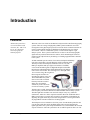
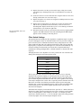
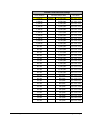
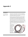
would be a good point to stop and find the analog interface cable and examine it you should find it packaged with a sheet of paper that provides some details of the
pin to cable connections. An analog connection cable with individual BNC
connectors is available on request.
The MA-300 also features a female 9-pin connector on the rear panel marked
“Option” (or “Display on some models). This connector provides signals for future
expansion of the MA-300 system. This connector supplies access to digital signals it does not contain any analog signals and should not be connected directly to any
analog data collection system.
The system installer should read the documentation that is provided with the data
collection system that is to be used with the MA-300 before starting the installation.
Since the MA-300 can be used with almost any data collection system it is difficult
to provide precise and specific instructions on every installation situation. However
the following issues are common to almost every situation:
MA-300 Outputs
All MA-300 outputs are static protected and voltage limited internally to no more
than ± 5 volts. Each output is single-ended, using a common signal return point, and
is driven by a current limited, low impedance source.
Signal Channels
The MA-300 system can support different numbers of signal channels that may
contain specific data. It is not always possible to translate MA-300 channel
numbering to use identical data collection channel numbers. Make sure that the
system user knows what MA-300 channels are connected and which channels the
data collection system uses to record or display EMG, Event Switch and Research
Data.
Note that the standard analog signal cable is supplied with connections for all sixteen
analog channels even when the system has only six or ten channels. If at all possible
it is recommended that all sixteen channels are connected when the system is first
installed as this will make any subsequent upgrades much easier if the user decides
to add additional EMG channels.
Ground
Also known as “Signal Return” - it is vital that the MA-300 Ground is connected to
the Analog ground (or signal return) of the users data collection system. Failure to
connect the MA-300 Signal Return will result in crosstalk and noisy signals. Most
initial data quality problems are caused by poor (or non-existent) ground
connections.
Data Parity
This is a TTL level signal that indicates any problems with the digital data
transmission. In most circumstances it can be ignored or connected to an unused
analog channel. If connected to an analog channel it will have a level of between
4.75 to 4.95V when EMG and other signals are being transmitted without any errors.
Do not connect this signal to any analog ground.
MA-300 Case
This is connected to the MA-300 case. It is an electrical ground for the metal case
and should be connected to the chassis or safety ground of the data collection system.
In many cases this can be connected to the analog signal ground. If problems are
58 • Appendix C
MA-300 EMG System User Guide