1
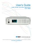
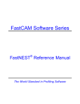
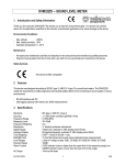
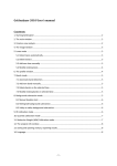
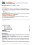
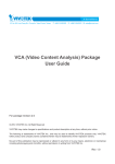
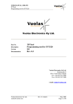
True shape nesting software
Astra S-Nesting
User’s manual
Contents
Contents ........................................................................................................................................................ 2 How to begin? ............................................................................................................................................... 3 Importing parts for nesting............................................................................................................................ 4 Entering plates for nesting ............................................................................................................................ 5 Automatic nesting ......................................................................................................................................... 5 Manual modification of layouts .................................................................................................................... 5 Printing documentation ................................................................................................................................. 8 Exporting the nesting results to DXF............................................................................................................ 9 Order Form.................................................................................................................................................... 9 Material Library .......................................................................................................................................... 10 CNG properties ........................................................................................................................................... 12 Developer and technical support................................................................................................................. 12 Astra S-Nesting • Nesting software for plate materials • User’s manual
2
How to begin?
Generally, you need to perform the following sequence of actions:
1. Import parts for nesting
Parts are imported from the DXF format (Drawing Exchange File). To import parts, use the Import
command in the File menu. The "Import parts…" dialog allows you to add files to import and enter the
parts’ properties.
Please see the detailed description of this task in the “Importing materials for nesting” section.
2. Enter plates for nesting
You can add plates using the Add plates command in the Nesting menu.
Please see the detailed description of this task in the "Entering plates for nesting" section.
3. Run automatic nesting
To start order nesting, run the Start nesting command in the Nesting menu.
The detailed description of the task can be found in the "Automatic nesting" section.
4. Manual modification of layouts
If you need to modify a layout manually, go to the Layouts tab in the Order Form, select it from the list
and run the Open command from the context menu.
The layout editing mode allows you to move and rotate parts using your mouse or special exact
positioning commands.
The detailed description of this task can be found in the “Manual editing of layouts” section.
5. Printing reports
The software allows you to print the following reports: draft of the current layout, drafts of the layouts
selected in the list, order parts specification, order layouts specification.
Please see the “Printing documents” section for details.
6. Exporting nesting results to DXF
In order to export the list of layouts to DXF, select them on the Layouts tab and run the Export
command from the context menu.
Please see “Exporting nesting results to DXF” for the detailed description of this task.
Astra S-Nesting • Nesting software for plate materials • User’s manual
3
Importing parts for nesting
Ctrl+I
Button on the Standard toolbar
Hotkeys
Parts are imported from the DXF (Drawing Exchange File) format. To import parts, use the Import
command from the File menu. File selection and configuration of part properties can be performed in the
"Import parts from DXF files" dialog window (see the screenshot).
To select the necessary files, press the Add button. You can simply drag dxf files from Windows
Explorer (or any other file manager) onto the File list window.
Once the files are selected, set the mandatory properties of the parts being imported: Thickness, Material
и Quantity. If necessary, enter the name of the Drawing and set Part numbering options.
If the necessary material is missing in the list, press the "…" button to the right of the Material field for
editing the Material library (see the Material library section).
The list of imported parts is added to the Parts tab of the Order Form (see Order Form).
Astra S-Nesting • Nesting software for plate materials • User’s manual
4
Entering plates for nesting
Ctrl+L
Button on the Order Form toolbar
Hotkeys
To add plates, use the Add plates command from the Nesting menu. Plate sizes can be entered in the
“Add plates for nesting” dialog window (see the screenshot).
Use the dialog window to enter the plate size, its thickness and quantity. If the quantity of plates is
unlimited, you don’t need to enter this value.
Select the plate material from the dropdown list. If the necessary material is missing in the list, press the
"…" button to the right of the Material field for editing the Material library (see Material library).
Automatic nesting
Ctrl+R
Button on the Standard toolbar
Hotkeys
For automatic order nesting, use the Run nesting command from the Nesting menu. Technological
nesting parameters are determined by the properties of the Concurrent Nesting Group (CNG).
IMPORTANT: Matching thickness and material type of the order plates and parts are mandatory
conditions for successful nesting. Parts made of the same material and having the same thickness
form a CNG. A single order may contain several CNG’s. Each CNG should contain plates for
nesting. If no plates are entered for a CNG, the software will notify the user.
Once the automatic nesting process is over, go to the Layouts tab of the Order Form to see the calculation
results.
Manual modification of layouts
If you need to manually adjust a layout, open the Layouts tab in the Order Form, select the layout in the
list and run the Open command from the context menu. To open several layouts, select them in the list
while holding down Ctrl or Shift. To change the relative position of the opened layout windows, use the
commands in the Window menu.
You can perform the following actions in the layout editing mode:
Astra S-Nesting • Nesting software for plate materials • User’s manual
5
Selecting groups of parts
All commands and operations on a layout are applied to a single part or a group of selected parts. Groups
can be selected using the mouse with the Shift key down or using the standard selection box. You will see
a highlighting box with rotation markers in its corners around the group of selected parts.
The Select all command in the Edit menu selects all the parts on the current layout.
Moving parts
You can move the selected parts in one of the following ways:
1) Use the mouse to move parts.
The part selection box looks like this:
The box can be moved to the nearest limit stop or the edge of the plate if dragged by the center. When a
part is dragged in any other way, it is moved without limit stop checks. Clicking any of the four edge
markers will move the part to the nearest corresponding limit stop.
If the Ctrl key is pressed, parts are moved to limit stops or the edge of the plate.
2) Parts can be moved using the arrow keys (up, down, left, right) to the nearest limit stops or the edge of
the plate. You can select the necessary step value or enter it in the Move by dropdown list on the Editing
toolbar.
3) Parts can be moved to limit stops (left, right, top, bottom) – other parts or the edge of the plate – with
the help of the Move - … to the limit stop command in the Edit menu. This command can be run
quickly by pressing one of the buttons on the Editing toolbar.
Move value
Move to the limit stop
Rotate value
Paralleling part edges
Part rotation
Rotation of selected parts is performed in one of the following ways:
1) Free mouse rotation is done using the rotation markers on the selection box. Press the left mouse
button on any marker and rotate the part.
2) Rotation by a specific angle can be performed using the Rotate command … in the Edit menu. The
rotation value is selected of entered in the dropdown list on the Editing toolbar.
Astra S-Nesting • Nesting software for plate materials • User’s manual
6
IMPORTANT: The software automatically controls the intersection of parts with each other and
the cutting path. Overlapping parts are marked with a special color. The default color is
“semitransparent red”. You can change the color of overlapping parts in the Layout – Color
section of the program’s Options.
Paralleling part edges
Button on the Editing toolbar
Paralleling part edges is a command mode that allows you to run the Parallel command several times
until the mode is disabled. To enable/disable this mode, use the Rotate – Parallel command in the Edit
menu.
The edge paralleling sequence is as follows:
1) Run the Parallel commands to enable the paralleling mode.
2) Click the part edge you want to place parallel to another one. For convenience, the edge below the
mouse cursor is highlighted with a special color.
3) Click the other edge to be paralleled with the first one.
Once you are finished, you can disable the paralleling mode.
Deleting parts
Parts can be deleted from the layout with the help of the Delete command in the Edit menu. Quick
deletion is carried out by pressing the Delete key.
Working with the clipboard
The following commands are available in the Edit menu when editing layouts and using the clipboard:
Cut – deletes the selected parts from the layout and places them into the clipboard.
Ctrl+X
Button on the Standard toolbar
Hotkeys
Copy – copies the selected parts into the clipboard. Running this command is only possible if the
multiplicity of the selected parts is more than 1 and there are unnested parts with this number in the order.
You can check the quantity of parts in the Part properties window, which is opened by the Properties
command on the layout.
Ctrl+C
Button on the Standard toolbar
Hotkeys
Paste – pastes parts from the clipboard into the current layout.
Ctrl+V
Button on the Standard toolbar
Hotkeys
Astra S-Nesting • Nesting software for plate materials • User’s manual
7
Undoing and redoing commands and operations
The Undo и Redo commands in the Edit window enable you to undo and redo commands and actions.
Scaling
The following commands are available in the View menu:
Fit to window – fits the layout to the window size.
Num*
Button on the View toolbar
Hotkeys
Zoom in – increases the zoom level by 2%.
Num+
Button on the View toolbar
Hotkeys
Zoom out – decreases the zoom level by 2%.
Num-
Button on the View toolbar
Hotkeys
Window scaling – enables the mode that allows you to use your mouse to set the window size for
zoomed viewing.
Button on the View toolbar
Previous view – sets the previous layout zoom level.
F3
Button on the View toolbar
Hotkeys
Panoramic – enables the layout sliding mode.
Button on the View toolbar
Mouse wheel rotation – performs the standard zooming functions.
Printing reports
Ctrl+P
Button on the Standard toolbar
Hotkeys
To print the active layout, run the Print command in the File menu. To print several layouts, select them
in the list on the Layouts tab of the Order Form prior to running this command. This command can also
be run from the context menu of the list of layouts.
To print the list of order layouts, run the Documents – Layouts command … in the Nesting menu. To
print the list of layouts, run the Documents – Parts command … in the Nesting menu.
Astra S-Nesting • Nesting software for plate materials • User’s manual
8
Exporting nesting results to DXF
Ctrl+E
Hotkeys
To export the active layout to DXF, run the Export command from the File menu. To export specific
layouts to DXF, select them in the list on the Layouts tab of the Order Form and run the Export
command from the context menu.
Order Form
This window contains all order data that are displayed on corresponding tabs: Parts, Plates and Layouts
(see the screenshot below).
The Parts tab
The Parts tab contains the list of Drawings, parts and the part preview window. The list of parts is
displayed according to the currently selected element in the Drawing list. If "– all – " is selected, the full
list of order parts is displayed.
Parts can be added to the list by importing them from DXF (see the "Importing parts for nesting" section).
You can delete the selected parts using the Delete command from the Edit menu.
Part properties can be viewed and edited in the Part properties dialog window, which is opened by the
Properties command from the context menu of the parts list. This window also allows you to change the
quantity of parts and their names.
The Plates tab
Plates can be added using the Add plates command in the Nesting menu (see the "Entering plates for
nesting" section). The command can be run by pressing the Ctrl+L combination in the context menu or
by clicking Button on the Order Form toolbar. Selected plates can be deleted by the Delete command in
the Edit menu.
Plate properties can be viewed and edited in the dialog window that is opened by the Properties
command in the plate list context menu. This window allows you to change the size and quantity of plates
if they are still unnested.
Nesting is performed automatically with the help of the Start nesting command in the Nesting menu (see
the “Automatic nesting" section). To manual nesting for selected plates only, use the Plate nesting
command from the plate list context menu.
Astra S-Nesting • Nesting software for plate materials • User’s manual
9
The Layouts tab
The layouts tab contains the list of order layouts. Layouts are added to the list during automatic nesting
(see the "Automatic nesting" section) or manual plate nesting. Selected layouts can be deleted by running
the Delete command in the context menu of the list of layouts.
You can open a layout for editing by double clicking on it in the list or by running the Open command in
the context menu of the list of layouts (see the "Manual editing of layouts" section).
To export layouts to DXF, select them in the list using the Ctrl or Shift keys and run the Export
command in the context menu.
To print layouts, select them in the list using the Ctrl or Shift keys and run the Print command in the
context menu.
The Order Form toolbar
The Order Form toolbar contains the following elements:
CNG filter – allows you to select the CNG filter; the list of parts is displayed according to the currently
selected filter options.
CNG properties – opens a window for previewing and editing the selected nesting group.
Add a plate – opens a dialog window for adding a plate for nesting.
Delete the selected element – deletes the selected element from the list depending on the currently active
tab: Parts, Plates or Layouts.
Material Library
The list of used materials and their properties can be found in the Material Library (see the screenshot),
which can be opened by the corresponding command from the File menu. The library can be also opened
by pressing the "…" button in the “Import parts” and “Add plates” dialog windows.
Astra S-Nesting • Nesting software for plate materials • User’s manual
10
The list of materials in the Library enables you to sort the list by each of the fields. To sort the list, leftclick on the header of the necessary column.
To add a new material to the Library, press the Add button. It will open the Material dialog window,
which allows you to set the following material properties: Type, Name, Supplier, Price per square foot,
Density (see the screenshot below). The Material Name property is mandatory.
To change the properties of a material, select it in the list and press the Change button.
To delete a material, select it in the list and press the Delete button.
Astra S-Nesting • Nesting software for plate materials • User’s manual
11
CNG properties
A set of parts of the same material and thickness is called a concurrent nesting group (CNG). Definition
of CNG properties is only possible after the parts have been imported, i.e. after the CNG has been
created. To define these properties, use the CNG properties command in the Nesting menu.
Choose the necessary CNG (if the order contains more than one CNG) in the CNG properties dialog
window (see the screenshot below), set its properties and press ОК.
The following properties can be set here:
Name of the layout group – it’s a prefix to be used for naming layouts in reports.
Number of the first layout – the number of the first layout in the current CNG.
Distance between parts – distance between parts on the layout.
Edge distance – allowed distance from parts on the layout and its edge.
You can define the default properties of a CNG – they will be used for all new concurrent nesting groups.
To do that, use the Default CNG in the File menu.
Developer and technical support
Technos LLC
Tel/fax (0512) 58-50-59
Astra S-Nesting • Nesting software for plate materials • User’s manual
12
Email: [email protected], [email protected]
Site: http://nesting.astrapro.ru
Address: 2A Rabochaya Str., Nikolaev, Office 601
Postal address: Technos, P.O.B 312, 54001 Nikolaev, Ukraine
Astra S-Nesting • Nesting software for plate materials • User’s manual
13