1
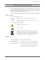
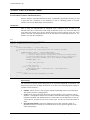
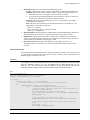
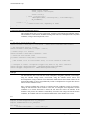
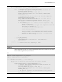
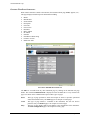
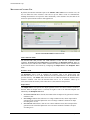
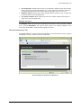
EX1200-7600
5 W PROGRAMMABLE
RESISTOR LADDER
USER’S MANUAL
P/N: 82-0127-006
Released September 8, 2010
VTI Instruments Corp.
2031 Main Street
Irvine, CA 92614-6509
(949) 955-1894
VTI Instruments Corp.
TABLE OF CONTENTS
TABLE OF CONTENTS .................................................................................................................................................. 2
Certification .......................................................................................................................................................... 4
Warranty ............................................................................................................................................................... 4
Limitation of Warranty ......................................................................................................................................... 4
Trademarks ........................................................................................................................................................... 4
Restricted Rights Legend ...................................................................................................................................... 4
GENERAL SAFETY INSTRUCTIONS ............................................................................................................................. 5
Terms and Symbols .............................................................................................................................................. 5
Warnings ............................................................................................................................................................... 5
SUPPORT RESOURCES ............................................................................................................................................... 7
SECTION 1 ................................................................................................................................................................... 9
INTRODUCTION ......................................................................................................................................................... 9
Overview............................................................................................................................................................... 9
Features................................................................................................................................................................. 9
Fault Sensing ................................................................................................................................................... 9
EX1200-7600 Specifications .............................................................................................................................. 11
Explanation of Specifications ............................................................................................................................. 12
Switching Time ............................................................................................................................................. 12
Setting Accuracy ........................................................................................................................................... 12
SECTION 2 ................................................................................................................................................................. 13
USING THE INSTRUMENT......................................................................................................................................... 13
Unpacking ........................................................................................................................................................... 13
Determine System Power Requirements ............................................................................................................. 13
Plug-in Module Installation ................................................................................................................................ 13
Maximizing Measurement Performance ............................................................................................................. 14
Warm Up Time.............................................................................................................................................. 14
Connector Pin/Signal Assignment ...................................................................................................................... 15
BPL_INSFAIL Behavior .................................................................................................................................... 17
SECTION 3 ................................................................................................................................................................. 19
PROGRAMMING THE INSTRUMENT .......................................................................................................................... 19
Introduction ........................................................................................................................................................ 19
Related Software Components ............................................................................................................................ 19
Using the Driver ................................................................................................................................................. 19
USING THE EX1200-7600 ....................................................................................................................................... 20
Initializing\Closing the Instrument...................................................................................................................... 20
Option Strings................................................................................................................................................ 20
Basic Operation .................................................................................................................................................. 21
Driver Interfaces ................................................................................................................................................. 24
APPLICATION EXAMPLE .......................................................................................................................................... 25
SECTION 4 ................................................................................................................................................................. 27
SFP OPERATION ..................................................................................................................................................... 27
Introduction ........................................................................................................................................................ 27
General Web Page Operation ............................................................................................................................. 28
VTI Instruments Logo ................................................................................................................................... 29
EX1200-7600 Soft Front Panel .......................................................................................................................... 29
2
EX1200-7600/-7600 Preface
www.vtiinstruments.com
Monitor and Control Tab .................................................................................................................................... 30
Failure Indicator LEDs .................................................................................................................................. 30
Resistance Field ............................................................................................................................................. 30
Output Source ................................................................................................................................................ 30
Backplane Line Source .................................................................................................................................. 31
Device Information Tab ...................................................................................................................................... 31
SECTION 5 ................................................................................................................................................................. 33
THEORY OF OPERATION .......................................................................................................................................... 33
Introduction ........................................................................................................................................................ 33
INDEX ......................................................................................................................................................................... 35
EX1200-7600 Preface
3
VTI Instruments Corp.
CERTIFICATION
VTI Instruments Corp. (VTI) certifies that this product met its published specifications at the time of shipment from
the factory. VTI further certifies that its calibration measurements are traceable to the United States National
Institute of Standards and Technology (formerly National Bureau of Standards), to the extent allowed by that
organization’s calibration facility, and to the calibration facilities of other International Standards Organization
members.
WARRANTY
The product referred to herein is warranted against defects in material and workmanship for a period of one year
from the receipt date of the product at customer’s facility. The sole and exclusive remedy for breach of any warranty
concerning these goods shall be repair or replacement of defective parts, or a refund of the purchase price, to be
determined at the option of VTI.
For warranty service or repair, this product must be returned to a VTI Instruments authorized service center. The
product shall be shipped prepaid to VTI and VTI shall prepay all returns of the product to the buyer. However, the
buyer shall pay all shipping charges, duties, and taxes for products returned to VTI from another country.
VTI warrants that its software and firmware designated by VTI for use with a product will execute its programming
when properly installed on that product. VTI does not however warrant that the operation of the product, or software,
or firmware will be uninterrupted or error free.
LIMITATION OF WARRANTY
The warranty shall not apply to defects resulting from improper or inadequate maintenance by the buyer, buyersupplied products or interfacing, unauthorized modification or misuse, operation outside the environmental
specifications for the product, or improper site preparation or maintenance.
VTI Instruments Corp. shall not be liable for injury to property other than the goods themselves. Other than the
limited warranty stated above, VTI Instruments Corp. makes no other warranties, express or implied, with respect to
the quality of product beyond the description of the goods on the face of the contract. VTI specifically disclaims the
implied warranties of merchantability and fitness for a particular purpose.
TRADEMARKS
Java Runtime Environment™ are trademarks or registered trademarks of Sun Microsystems, Inc. or its subsidiaries
in the United States and other countries. LabVIEW™ and LabWindows/CVI™ are trademarks of National
Instruments Corporation. Visual Basic®, Windows®, and Internet Explorer® are registered trademarks of the
Microsoft Corporation or its subsidiaries. Linux® is a registered trademark of the Linux Foundation. IVI™ is a
trademark of the IVI Foundation. Bonjour™ is a trademark of Apple, Inc.
RESTRICTED RIGHTS LEGEND
Use, duplication, or disclosure by the Government is subject to restrictions as set forth in subdivision (b)(3)(ii) of the
Rights in Technical Data and Computer Software clause in DFARS 252.227-7013.
VTI Instruments Corp.
2031 Main Street
Irvine, CA 92614-6509 U.S.A.
4
EX1200-7600/-7600 Preface
www.vtiinstruments.com
GENERAL SAFETY INSTRUCTIONS
Review the following safety precautions to avoid bodily injury and/or damage to the product.
These precautions must be observed during all phases of operation or service of this product.
Failure to comply with these precautions, or with specific warnings elsewhere in this manual,
violates safety standards of design, manufacture, and intended use of the product. Note that this
product contains no user serviceable parts or spare parts.
Service should only be performed by qualified personnel. Disconnect all power before servicing.
TERMS AND SYMBOLS
These terms may appear in this manual:
WARNING
Indicates that a procedure or condition may cause bodily injury or death.
CAUTION
Indicates that a procedure or condition could possibly cause damage to
equipment or loss of data.
These symbols may appear on the product:
ATTENTION - Important safety instructions
Frame or chassis ground
Indicates that the product was manufactured after August 13, 2005. This mark is
placed in accordance with EN 50419, Marking of electrical and electronic
equipment in accordance with Article 11(2) of Directive 2002/96/EC (WEEE).
End-of-life product can be returned to VTI by obtaining an RMA number. Fees
for take-back and recycling will apply if not prohibited by national law.
WARNINGS
Follow these precautions to avoid injury or damage to the product:
Use Proper Power Cord
To avoid hazard, only use the power cord specified for this product.
Use Proper Power Source
To avoid electrical overload, electric shock, or fire hazard, do not
use a power source that applies other than the specified voltage.
The mains outlet that is used to power the equipment must be
within 3 meters of the device and shall be easily accessible.
EX1200-7600 Preface
5
VTI Instruments Corp.
WARNINGS (CONT.)
Avoid Electric Shock
To avoid electric shock or fire hazard, do not operate this product
with the covers removed. Do not connect or disconnect any cable,
probes, test leads, etc. while they are connected to a voltage source.
Remove all power and unplug unit before performing any service.
Service should only be performed by qualified personnel.
Ground the Product
This product is grounded through the grounding conductor of the
power cord. To avoid electric shock, the grounding conductor must
be connected to earth ground.
Operating Conditions
To avoid injury, electric shock or fire hazard:
Do not operate in wet or damp conditions.
Do not operate in an explosive atmosphere.
Operate or store only in specified temperature range.
Provide proper clearance for product ventilation to prevent
overheating.
DO NOT operate if any damage to this product is suspected.
Product should be inspected or serviced only by qualified
personnel.
The operator of this instrument is advised that if the equipment is
used in a manner not specified in this manual, the protection
provided by the equipment may be impaired.
Conformity is checked by inspection.
Improper Use
6
EX1200-7600 Preface
www.vtiinstruments.com
SUPPORT RESOURCES
Support resources for this product are available on the Internet and at VTI Instruments customer
support centers.
VTI Instruments Corp.
World Headquarters
VTI Instruments Corp.
2031 Main Street
Irvine, CA 92614-6509
Phone: (949) 955-1894
Fax: (949) 955-3041
VTI Instruments
Cleveland Instrument Division
5425 Warner Road
Suite 13
Valley View, OH 44125
Phone: (216) 447-8950
Fax: (216) 447-8951
VTI Instruments
Lake Stevens Instrument Division
3216 Wetmore Avenue, Suite 1
Everett, WA 98201
Phone: (949) 955-1894
Fax: (949) 955-3041
VTI Instruments, Pvt. Ltd.
Bangalore Instrument Division
642, 80 Feet Road
Koramangala IV Block
Bangalore – 560 034
India
Phone: +91 80 4040 7900
Phone: +91 80 4162 0200
Fax: +91 80 4170 0200
Technical Support
Phone: (949) 955-1894
Fax: (949) 955-3041
E-mail: [email protected]
Visit http://www.vtiinstruments.com for worldwide support sites and service plan information.
EX1200-7600 Preface
7
VTI Instruments Corp.
8
EX1200-7600 Preface
www.vtiinstruments.com
SECTION 1
INTRODUCTION
OVERVIEW
The EX1200-7600 is a single channel, programmable resistor ladder. It is designed for
applications such as RTD or other resistance-based sensor simulation, process control, ATE
calibration, and controlled loading of device under test (DUT). It contains internal, high-precision
5 W power resistors that are switched via electromechanical relays. The EX1200-7600 is capable
of producing any resistance value between 0.5 Ω to 1,500,000 Ω and can be adjusted in 0.1 Ω
increments via program commands. It is designed for terminal voltages from 0 V to 200 V dc and
for currents up to 0.5 A.
The EX1200-7600 is part of the EX1200 family of products and can be mixed and matched with
other EX1200 series modules to configure high-density measurement and switching systems.
FEATURES
Fault Sensing
After power up, reset, or a fault condition, the input will be internally disconnected and the
resistance will be set to its maximum value. This open circuit configures the EX1200-7600 to its
highest resistance, removing the load from the device under test. A fault condition is the result of
exceeding the maximum current, maximum voltage or maximum temperature for the module.
Additionally, the module will respond to the chassis BPL_INSFAIL circuit, which can be used to
open all relays on all cards in a chassis simultaneously. A voltage sense out signal provides a
scaled indication of the voltage across the resistance, and a current sense out signal provides a
scaled indication of the current through the circuit, both of which can be monitored by an external
measurement device (such as an EX1200 series DMM). This can be used to force all relays open if
a set voltage or current is exceeded thereby protecting the unit under test.
EX1200-7600 Introduction
9
VTI Instruments Corp.
RES1A
K32
K31
K30
K29
K28
K11
524.288 Kohm
K24
K12
1.048576 Mohm
K25
128 ohm
K10
64 ohm
K44
32 ohm
K43
K9
16 ohm
K42
K8
8 ohm
K41
K7
4 ohm
K40
K6
2 ohm
K39
K5
1 ohm
K38
K4
0.4 ohm
K37
K3
0.4 ohm
K36
K2
0.2 ohm
K35
K34 K1
K33
0.1 ohm
V_SENSE_OUT
SENSE_RET
256 ohm
K13
512 ohm
K14
0.15 ohm
0.2 ohm
SENSE_RET
K17
4096 ohm
K16
K26
K27
2048 ohm
I_SENSE_OUT
K15
1024 ohm
AGND
K20
32.768 Kohm
K19
16.384 Kohm
K18
8192 ohm
65.536 Kohm
K21
131.072 Kohm
K22
K23
262.144 Kohm
FIGURE 1-1: LOGICAL BLOCK DIAGRAM
10
EX1200-7600 Introduction
www.vtiinstruments.com
EX1200-7600 SPECIFICATIONS
GENERAL SPECIFICATIONS
MODEL TYPE
Programmable resistor load
CHANNELS
1
SWITCHING TIME
< 5 ms
RATED SWITCH OPERATIONS
5 x 10⁶
Mechanical
1 x 10⁵ (full-load)
Electrical
OVER-TEMPERATURE PROTECTION
102 °C (215.6 °F)
PCB surface temperature
POWER SPECIFICATIONS
MAXIMUM SWITCHING VOLTAGE
200 V ac rms
MAXIMUM SWITCHING CURRENT
0.5 A
MAXIMUM SWITCHING/CARRY POWER
5W
POWER CONSUMPTION
0.129 A
3.3 V
0.0041 A (add 24 mA for each relay closure)
5V
0.2 A (maximum value)
24 V
RESISTOR PERFORMANCE
VOLTAGE OUTPUT RANGE/GAIN
40:1 ±1% full-scale
CURRENT OUTPUT RANGE/GAIN
100:1 ±1% full-scale
SETTINGS ACCURACY
±0.15 Ω
0.5 – 60.0 Ω
±0.25 % of programmed value
60.1 – 1,499,999 Ω
Not specified
1,499,999.1 Ω - 2,097,152.6 Ω
MINIMUM INCREMENT (RESOLUTION)
0.1 Ω
CONNECTOR INFORMATION
MATING CONNECTOR
VTI Part Number
Manufacturer/Part Number
CONNECTOR BACKSHELL
VTI Part Number
Manufacturer/Part Number
EX1200-7600 Introduction
27-0076-015
Positronic HDC15F20000
27-0086-015
Amp 5-747099-1
11
VTI Instruments Corp.
EXPLANATION OF SPECIFICATIONS
This section provides explanatory notes to certain elements of the EX1200-7600 specification that
may be misunderstood.
Switching Time
This specification defines the amount of time needed for the resistance value to settle to the
commanded value. The resistance value may increase or decrease during this time. If the
connected, external equipment is sensitive to these this variance in resistance, it may be necessary
to take any needed precautions, such as connecting an external capacitor to reduce the effect of the
step changes.
Setting Accuracy
The accuracy of the EX1200-7600 is dependent on the amount of resistance that is programmed.
The specification indicates the accuracy for each of three ranges of resistance. Note that, although
the EX1200-7600 can be set to values above 1,499,999 Ω, the accuracy for these loads is not
specified.
12
EX1200-7600 Introduction
www.vtiinstruments.com
SECTION 2
USING THE INSTRUMENT
UNPACKING
When an EX1200-7600 is unpacked from its shipping carton, the contents should include the
following items:
•
•
•
•
An EX1200-7600
LXI Quick Start Guide
EX1200-7600 User’s Manual (this manual)
EX1200-7600 IVI, Linux, or LabView Driver (included on Distribution CD)
All components should be immediately inspected for damage upon receipt of the unit. ESD
precautions should be observed while unpacking and installing the instrument into an EX1200
series mainframe.
DETERMINE SYSTEM POWER REQUIREMENTS
The power requirements of the EX1200 mainframes are provided in the Specifications section of
Section 1. It is imperative that the mainframe provide adequate power for the modules installed.
For more information on EX1200 mainframe power consumption, please refer to the EX1200
Series User’s Manual (P/N: 82-0127-000) for more information. The user should confirm that the
power budget for the system (for the chassis and all modules installed therein) is not exceeded on
any voltage line.
It should be noted that if the mainframe cannot provide adequate power to the module, the
instrument might not perform to specification and possibly damage the power supply. In addition,
if adequate cooling is not provided, the reliability of the instrument will be jeopardized and
permanent damage may occur. Damage found to have occurred due to inadequate cooling will void
the warranty on the instrument in question.
NOTE
For more information on power requirement calculations, refer to and review Appendix B in the
EX1200 Series User’s Manual to ensure that the current limits of the power supply are not
exceeded.
PLUG-IN MODULE INSTALLATION
Before installing a plug-in module into an EX1200 system, make sure that the mainframe is
powered down. Insert the module into the base unit by orienting the module so that the metal cover
of the module can be inserted into the slot of the base unit. Position the cover so that it fits into the
module’s slot groove. Once the module is properly aligned, push the module back and firmly insert
it into the backplane connector. See Figure 2-1 for guidance.
EX1200-7600: Using the Instrument
13
VTI Instruments Corp.
Guide
PCB
FIGURE 2-1: MODULE INSTALLATION (EX1200-3048 USED AS EXAMPLE)
MAXIMIZING MEASUREMENT PERFORMANCE
This section discusses tips and procedures that can help maximize the actual performance realized
with the EX1200-7600 and aid the user in avoiding some common pitfalls associated with making
measurements.
Warm Up Time
The specified warm-up time for an EX1200 system is 30 minutes. If, however, the unit is being
subjected to an ambient temperature change greater than 5 ºC, extra stabilization time is
recommended to achieve maximum performance.
14
EX1200-7600: Using the Instrument
www.vtiinstruments.com
CONNECTOR PIN/SIGNAL ASSIGNMENT
The connector pins and their signal assignments are shown in Table 2-1 and Figure 2-1 below. For
mating connector and accessory information, please see the EX1200-7600 Specifications.
FIGURE 2-2: EX1200-7600 FRONT PANEL DETAIL
Pin
1
2
3
4
5
6
7
8
9
10
11
12
13
14
15
Signal
RES1A
RES1A
UNUSED
GND_C
UNUSED
FP_OPEN
V_SENSE_OUT
I_SENSE_OUT
AGND
AGND
UNUSED
UNUSED
FP_GND
SENSE_RET
SENSE_RET
TABLE 2-1: EX1200-7600 CONNECTOR PIN SIGNAL ASSIGNMENT
EX1200-7600: Using the Instrument
15
VTI Instruments Corp.
The purpose of each signal is defined in Table 2-2.
Signal
RES1A
GND_C
AGND
FP_OPEN
FP_GND
V_SENSE_OUT
I_SENSE_OUT
SENSE_RET
Description
Input at the resistor terminals.
The chassis ground. This pin is usually connected to cable shield.
The analog ground. This pin can be used when the user’s signal has its own ground
separate from chassis ground mentioned above.
A Low signal at this pin opens up all the relays and the resistance path is open.
when FP-OPEN is restored high, it return back to the previous set relay driver
status.
Ground pin for the FP_OPEN signal.
The voltage sense line. This pin provides access to the scaled-down input voltage
of RES1A. The resistance is scaled down 40:1 ± 1% of the full-scale setting.
The current sense line. This pin provides access to the scaled-down input current of
RES1A. The resistance is scaled down 100:1 ±1% of the full-scale setting.
The return path for voltage/current sense lines.
TABLE 2-2: SIGNAL PIN DEFINITIONS
RES1A
RES1A
Program
Control
AGND
AGND
V_SENSE_OUT
I_SENSE_OUT
÷40 Voltage
scaling
÷100 I to V
conversion and
scaling
SENSE_RET
GND_C
FIGURE 2-3: INTERNAL CONNECTIVITY OF THE FRONT PANEL PINS
Note that there are two RES1A and AGND terminals. These connections are provided to facilitate
the use of 4-wire resistance simulations. For example, to simulate a 4-wire RTD, these terminals
act as the excitation and sense terminals. Electrically, both RES1A and AGD terminals are parallel,
and, therefore, interchangeable. While using a 2-wire resistor, these terminals can be shorted
externally to provide lower contact resistance.
16
EX1200-7600: Using the Instrument
www.vtiinstruments.com
BPL_INSFAIL BEHAVIOR
The EX1200 platform backplane has a BPL_INSFAIL line that indicates to all modules that a
severe failure has occurred. When this line is asserted, all of the relays on the EX1200-7600 will
be opened, leaving the circuit open.
EX1200-7600: Using the Instrument
17
VTI Instruments Corp.
18
EX1200-7600: Using the Instrument
www.vtiinstruments.com
SECTION 3
PROGRAMMING THE INSTRUMENT
INTRODUCTION
This section provides programming examples for the EX1200-7600. Additional information can be
found in the driver help file. If the instrument will be used on a Linux system, a .chm viewer must
be installed on the host PC (examples of these programs can be found at the following URL:
http://www.linux.com/news/software/applications/8209-chm-viewers-for-linux.)
NOTE
Programming examples are installed with the IVI Driver – VarRes, typically located in the “<HDD
Designation>\Program Files\IVI Foundation\IVI\Drivers\VTEXVarRes\Examples“ folder.
RELATED SOFTWARE COMPONENTS
IVI-COM Driver
IVI-C Driver
LabView Driver
Linux C++ Driver
USING THE DRIVER
The EX1200-7600 may be used in a variety of environments including: Visual Basic, C#, C++,
LabView. VTI instruments provides a IVI-C and IVI-COM compliant driver as well as a shared
object that can be used on Linux systems that comply with the Linux Standard Base (Version 3.1).
Here is how to use the driver in each environment:
1) Visual Studio C++
#import "IviDriverTypeLib.dll" no_namespace
#import "VTEXVarRes.dll" no_namespace
2) C#
Add a reference to VTEXVarRes.dll in the project. Include the following at the top of any
code file that will access the driver:
using VTI.VTEXVarRes.Interop;
3) C/C++ on Windows
Link against VTEXVarRes.lib and include VTEXVarRes.h in the file.
4) C++ on Linux
Link against /opt/vti/lib/libvarres.so and include all the headers in /opt/vti/include in the
source file.
5) LabView
Copy the driver package to the <Labview>/instr.lib directory and access all relevant VIs
EX1200-7600: Programming the Instrument
19
VTI Instruments Corp.
USING THE EX1200-7600
INITIALIZING\CLOSING THE INSTRUMENT
The base interface of the EX1200-7600 IVI driver, VTEXVarRes (LibVarRes on Linux), is used
to open and close connections to the instrument as well as containing pointers to all other
interfaces to access the functionality of the instrument.
Initialization
Prior to using the EX1200-7600, an instrument driver connection must be made to the
EX1200-7600. Once a connection is made using the Initialize call, the user can execute their test
code. Before the program exits, the user should release the resources using the Close call. Users
familiar with other VTI Instrument Drivers for the EX1200 series should find this driver is very
similar to ones they have used before.
C++
#import "IviDriverTypeLib.dll" no_namespace
#import "VTEXVarRes.dll" no_namespace
int main() {
::CoInitialize(NULL); // start COM layer
// try/catch so driver not found situations are properly handled
try {
IVTEXVarResPtr varres(__uuidof(VTEXVarRes));
try { // second error layer for failed initialize
/* using an empty options string here; see Option Strings below
for more infomration;also using Reset bit to get a clean init */
varres->Initialize("TCPIP::10.1.4.55::INSTR", VARIANT_TRUE,
VARIANT_TRUE, "");
// test code goes here
varres->Close();
} catch (_com_error &e) {
::MessageBox(NULL, e.Description(), e.ErrorMessage(),
MB_ICONERROR);
}
} catch (...) {
// handle errors here, depending on needs
}
}
Option Strings
The VTEX drivers provide option strings that can be used when Initializing an instrument. The
option string values exist to change the behavior of the driver. The following options strings are
available on VTI IVI drivers:
•
•
•
20
Simulate: Allows the user to run a program without commanding switch card or instruments.
This option is useful as a debugging tool.
Cache: Per the IVI specification, this option “specifies whether or not to cache the value of
attributes.” Caching allows IVI drivers to maintain certain instrument settings to avoid sending
redundant commands. The standard allows for certain values to be cached always or never. In
VTI IVI-drivers, all values used are of one of these types. As such, any values entered have no
effect.
QueryInstrumentStatus: Queries the instrument for errors after each call is made. As
implemented in the VTI IVI drivers, instruments status is always queried regardless of the
value of this property.
EX1200-7600: Programming the Instrument
www.vtiinstruments.com
•
•
•
•
DriverSetup: Must be last, and contains the following properties:
o Logfile: Allows the user to specify a file to which the driver can log calls and other data.
o Logmode: Specifies the mode in which the log file is opened. The allowed modes are:
• w: truncate s the file to zero length or creates a text file for writing.
• a: opens the file for adding information to the end of the file. The file is created if it
does not exist. The stream is positioned at the end of the file.
o LogLevel: Allows the user to determine the severity of a log message by providing a
level-indicator to the log entry.
o Slots: This is the most commonly used option and it allows for a slot number or a slot
number and a card model to be specified.
"Slots=(2)" - Just slot 2.
"Slots=(2=EX1200_3048)" - slot and card model
"Slots=(2,3)" - Multiple slots
InterchangeCheck: Boolean option that enables/disables IVI Interchangeability checking. As
implemented in the VTI IVI drivers, values entered for this property have no effect.
RangeCheck: Boolean option that enables or disables driver validation of user-submitted
values. As implemented in the VTI IVI drivers, validation of user inputs is always performed
at the firmware level regardless of this property’s value.
RecordCoercions: Boolean option that enables driver recording of coercions. As
implemented in the VTI IVI drivers, coercions are handled in the firmware and cannot be
recorded.
BASIC OPERATION
The EX1200-7600 has single channel that is capable of producing resistance values between 0.5 Ω
to 1,499,999 Ω in 0.1 Ω increments with specified accuracy. All relays will be opened unless the
Enabled property of channel is set to true.
Resistance
This example covers the main functionality of the device: setting a resistance to be used as a load.
Note that, although resistance is set on a per-channel basis, the EX1200-7600 has only one
channel: “CH1”. Also note that the resistance should be set first, then enabled. This prevents
enabling the channel with the default resistance enabled, which is the maximum value.
C++
#using <mscorlib.dll>
#import "IviDriverTypeLib.dll" no_namespace
#import "VTEXVarRes.dll" no_namespace
int main() {
::CoInitialize(NULL); // start COM layer
// try/catch so driver not found situations are properly handled
try {
IVTEXVarResPtr varres(__uuidof(VTEXVarRes));
try { // second error layer for failed initialize
/* using an empty options string here; check the manual for
available options strings;
also using Reset bit to get a clean init */
varres->Initialize("TCPIP::10.1.4.55::INSTR", VARIANT_TRUE,
VARIANT_TRUE, "");
// only channel on this device is "CH1"
IVTEXVarResChannelPtr ch1 = varres->Channels->Item["CH1"];
// setting an output coerces it to the nearest possible
value
ch1->Output = 3.0;
ch1->Enabled = VARIANT_TRUE;
EX1200-7600: Programming the Instrument
21
VTI Instruments Corp.
// retrieving it will return its actual setting
double actual_output;
actual_output = ch1->Output;
varres->Close();
} catch (_com_error &e) {
::MessageBox(NULL, e.Description(), e.ErrorMessage(),
MB_ICONERROR);
}
} catch (...) {
// handle errors here, depending on needs
}
}
Configuring Channels and Backplane Trigger
This example shows how to set the switch mode, resistance, and configure the backplane trigger.
This stimulates a 1 kΩ resistance in BBM switching mode and raises a backplane0 line if any fault
conditions (voltage/current/temperature) occur.
C++
// The relay switch mode to BBM.
VarRes->Channels->Item["CH1"]->SwitchMode = VTEXVarResSwitchModeBreakBeforeMake;
// The resistance value to 1k Ohm.
VarRes->Channels->Item["CH1"]->Output = 1000.0;
// Enable relays of a channel.
VarRes->Channels->Item["CH1"]->Enabled = true;
// Check the over-current state
if(VarRes->Channels->Item["CH1"]->OverCurrent)
{
//The channel is in an over-current state, so action should be taken here.
}
// Configure to assert a backplane trigger line, BPL0 in any error condition.
VarRes->Trigger->BackplaneOutput = VTEXVarResBackplaneTriggerBPL0;
VarRes->Trigger->OutputSource = VTEXVarResOutputSourceAny;
Fail-safe
The EX1200-7600 has several fail-safe modes: Backplane, using BPL_INSFAIL; OverVoltage,
using the onboard voltage sensor; OverCurrent, using the onboard current sensor; and
OverTemperature, using a collection of six thermistors mounted on the board. Each of these can be
checked individually or can be programmatically routed to a backplane line to signal other devices
when a fail-safe condition occurs.
Once a fail-safe condition has occurred, it is latched. Fail-safe conditions can only be cleared by
calling the EX1200-7600’s Reset function. Note that, for backplane and temperature fail-safe
conditions to be cleared when Reset is called, the user must also remove the stimulus. If the
stimulus is still present, the condition is immediately re-asserted. For voltage and current fail-safe
conditions, the condition will not recur until the Enabled state of the channel is set to True.
C++
#using <mscorlib.dll>
#import "IviDriverTypeLib.dll" no_namespace
#import "VTEXVarRes.dll" no_namespace
int main() {
::CoInitialize(NULL); // start COM layer
22
EX1200-7600: Programming the Instrument
www.vtiinstruments.com
// try/catch so driver not found situations are properly handled
try {
IVTEXVarResPtr varres(__uuidof(VTEXVarRes));
try { // second error layer for failed initialize
/* using an empty options string here; check the manual for
available options strings;
also using Reset bit to get a clean init */
varres->Initialize("TCPIP::10.1.4.55::INSTR", VARIANT_TRUE,
VARIANT_TRUE, "");
/* BackplaneFailsafe will be true if the failsafe trigger has
occurred since the last reset;
this trigger prevents damage to the card by locking open all
relays under well-defined conditions
like extreme temperatures or excess voltage. */
bool bpl_fail = varres->BackplaneFailsafe == VARIANT_TRUE;
if (bpl_fail) {
/* OverTempurate is a bitmask; each bit represents a temp
sensor on the board,
and is 1 if that sensor has gone over temperature since the
last reset, 0 otherwise */
int overtemp = varres->OverTemperature;
varres->Utility->Reset();
/* It is possible for BackplaneFailsafe to remain true
through a reset, if the condition that caused a failsafe
continues to exist. It will not reset to a usable state
until it can do so safely. */
}
varres->Close();
} catch (_com_error &e) {
::MessageBox(NULL, e.Description(), e.ErrorMessage(),
MB_ICONERROR);
}
} catch (...) {
// handle errors here, depending on needs
}
}
Odometers
The EX1200-7600 also offers a set of relay odometers that allows users to track relay wear. This is
made available programmatically via the driver.
C++
#using <mscorlib.dll>
#import "IviDriverTypeLib.dll" no_namespace
#import "VTEXVarRes.dll" no_namespace
int main() {
::CoInitialize(NULL); // start COM layer
// try/catch so driver not found situations are properly handled
try {
IVTEXVarResPtr varres(__uuidof(VTEXVarRes));
try { // second error layer for failed initialize
/* using an empty options string here; check the manual for
available options strings;
also using Reset bit to get a clean init */
varres->Initialize("TCPIP::10.1.4.55::INSTR", VARIANT_TRUE,
VARIANT_TRUE, "");
/* The physical properties of electromechanical relays dictate
that they wear over time,
EX1200-7600: Programming the Instrument
23
VTI Instruments Corp.
becoming less reliable and eventually unusable. The odometer check
is used to determine
when the releys on the card are approaching end of life by keeping
a count of switch events. */
/* The GetOdometers function populates a SAFEARRAY with the
odometer counts for the relays specified as a comma separated list
of relay names in BSTR. */
_bstr_t relays = “K1, K2, K13”;
SAFEARRAY* odoms = NULL;
varres->GetOdometers(relays, &odoms);
varres->Close();
} catch (_com_error &e) {
::MessageBox(NULL, e.Description(), e.ErrorMessage(),
MB_ICONERROR);
}
} catch (...) {
// handle errors here, depending on needs
}
}
DRIVER INTERFACES
The following is a list of programmatic interfaces to the EX1200-7600 with a description of the
functionality they provide. Please refer to the help file installed with the driver for a programming
reference that includes all methods with their parameters as well as all enumerations.
•
•
•
•
•
•
•
24
IVTEXVarRes: Used to open and close connections to the instrument. Also contains Failsafe
information that is per-card, such as Temperature.
Channels: Used to configure or query individual channel state such as resistance value, relay
switching mode or over voltage/current status.
DriverOperation: IVI standard. Provides control over the manner in which the driver
operates.
Identity: IVI standard. Provides detailed version information about the driver, connected
hardware, and firmware versions.
Platform: Used to Log driver function calls and to retrieve the serial number of the
instrument.
Trigger: Used to configure trigger condition and select a backplane trigger line to be asserted.
Utility: IVI standard. Provides useful functionality not specific to this driver, such as Reset.
EX1200-7600: Programming the Instrument
www.vtiinstruments.com
APPLICATION EXAMPLE
This example simulates PT100 RTD using EX1200-7600. The temperature range is simulated
from -200 °C to 850 °C.
// RTD Simulation using EX1200-7600(2).cpp : main project file.
#include "stdafx.h"
#using <mscorlib.dll>
#import "IviDriverTypeLib.dll" no_namespace
#import "VTEXVarRes.dll" no_namespace
using namespace System;
double const START_TEMP = -200;
double const END_TEMP = 850;
//starting temperaure range
//ending temperature range
double const A= 3.9083* pow(10.0F,(int)-3);
//RTD material constant
double const B = -5.775* pow(10.0F,(int)-7);
//RTD meterial constant
double const Ro = 100;
//Temperature at 0'C
int _tmain()
{
::CoInitialize(NULL); //Start the COM layer
/*We want to instantiate a pointer to the driver in a try/catch block so that we
fail properly if the driver is not found in the COM registry*/
try
{
IVTEXVarResPtr VarRes(__uuidof(VTEXVarRes));
/*We want to do the Initialization a try/catch block so that our test
code doesn't run if we fail to initialize.*/
try
{
double temperature;
std::cout<<"RTD Simulation using EX1200-7600 programmable
resistance card"<<std::endl;
/*We chose to give the driver an empty options string. You
may want to give your driver options - check the manual to see the available settings.
change the Instrument ID string accordingly*/
VarRes>Initialize("TCPIP::10.30.1.45::INSTR",VARIANT_TRUE,VARIANT_TRUE, "");
VarRes->Channels->Item["CH1"]->Enabled = true;
//Enabling the channel for use
VarRes->Channels->Item["CH1"]->SwitchMode =
VTEXVarResSwitchModeBreakBeforeMake; // Break(to high resistance) before setting the
resistance
std::cout<<"Enter the temperature value to be set(-200'C to
850'C):";
std::cin>>temperature;
if(temperature>= START_TEMP && temperature <=END_TEMP)
{
//Temperature to resistance as per Callendar–Van
Dusen equation
double C = temperature<0?(-4.183* pow(10.0F,(int)12)):0;
VarRes->Channels->Item["CH1"]->Output = (Ro * (1 + A*
temperature + B*pow(temperature,2) + C*(temperature-100)* pow(temperature,3)));
std::cout<<"Actual set Resistance:"<<VarRes>Channels->Item["CH1"]->Output<<std::endl;//Retrivers the acutal resistance from the
device
}
//Close the initialized session
VarRes->Close();
}
catch(_com_error &e)
{
EX1200-7600: Programming the Instrument
25
VTI Instruments Corp.
::MessageBox(NULL, e.Description(), e.ErrorMessage(),
MB_ICONERROR);
}
}
catch(...)
{
//We put this here to catch any error the program generates.
//Do something to intelligently deal with errors
}
return 0;
}
26
EX1200-7600: Programming the Instrument
www.vtiinstruments.com
SECTION 4
SFP OPERATION
INTRODUCTION
EX1200s offer an embedded web page which provides network configuration control, time
configuration, and the ability to perform firmware upgrades. To facilitate discovery of the
mainframe, VTI provides the LAN Instrument Connection and Upgrade (LInC-U) utility on the
VTI Instruments Corp. Drivers and Product Manuals CD included with the EX1200 mainframe in
the EX Platforms Requisites directory.
To open the embedded web page, start the LInC-U utility by navigating to Start → Programs →
VTI Instruments Corporation → LInC-U Utility → LInC-U Utility. Once the utility is run,
LInC-U will scan the network to discover all LAN-based VTI instruments. Once the scan is
complete, the Discovery Devices tab will appear and show the instruments that were discovered,
as shown in Figure 4-1. To open the web page, click on the hostname hyperlink in the Discover
Devices tab. The IP address of the EX1200 can also be viewed from this window as well as its
firmware version.
FIGURE 4-1: LINC-U DISCOVERY TAB WITH AN EX1268 SELECTED
Alternatively, the EX1200 may also be discovered using Internet Explorer’s Bonjour for Windows
plug-in, by entering the mainframe’s IP address into the address bar of any web browser to view
the embedded web page, or using VXI-11. For more information on discovery methods, refer to
the EX1200 Series User’s Manual (P/N: 82-0127-000).
EX1200-7600: SFP Operation
27
VTI Instruments Corp.
GENERAL WEB PAGE OPERATION
When initial connection is made to the EX1200, the instrument home page, Index, appears (see ).
This page displays instrument-specific information including:
•
•
•
•
•
•
•
•
•
•
•
•
•
Model
Manufacturer
Serial Number
Description
LXI Class
LXI Version
Hostname
MAC Address
IP Address
Netmask
Instrument Address String
Firmware Version
IEEE-1588 Time
FIGURE 4-2: EX1200 MAIN WEB PAGE
The Index is accessible from any other instrument page by clicking on the EX1200 web page
header. The EX1200 Command Menu is displayed on the left-hand side of every internal web
page. The entries on the command menu represent three types of pages:
Status
Action
Entry
28
This type of page performs no action and accepts no entries. It provides operational
status and information only. The Index page is an example of a status page.
This type of page initiates a command on the instrument, but does not involve
parameter entry. The Reboot page is an example of an action page.
This type of page displays and accepts changes to the configuration of the instrument.
The Time Configuration page is an example of an entry page.
EX1200-7600: SFP Operation
www.vtiinstruments.com
Use of the entry-type web pages in the EX1200 are governed by a common set of operational
characteristics:
•
•
•
Pages initially load with the currently-entered selections displayed.
Each page contains a Submit button to accept newly entered changes. Leaving a page before
submitting any changes has the effect of canceling the changes, leaving the instrument in its
original state.
Navigation through a parameter screen is done with the Tab key. The Enter key has the same
function as clicking the Submit button and cannot be used for navigation.
Notes on Web Page Use
If a window needs to be resized, this should be done when the window opens. Resizing requires a
refresh which causes the current state to be lost.
VTI Instruments Logo
The VTI Instruments logo that appears on the upper left of all EX1200 web pages is a link to the
VTI Instruments corporate website: http://www.vtiinstruments.com.
The remainder of this discussion will focus on the EX1200-7600 soft front panel. For more
information on other EX1200 soft front panel elements, please refer to the EX1200 Series User’s
Manual.
EX1200-7600 SOFT FRONT PANEL
To navigate to the EX1200-7600 soft front panel, click on Soft Front Panel in the Command
Menu (see Figure 4-3). Next, select ex1200-7600 Variable Resistance from the list of cards
installed in the EX1200.
FIGURE 4-3: EX1200 SOFT FRONT PANEL MAIN PAGE
EX1200-7600: SFP Operation
29
VTI Instruments Corp.
MONITOR AND CONTROL TAB
By default, the EX1200-7600 SFP opens to the Monitor and Control view. From this view, the
user can define the load’s resistance value and set up how failure events are communicated.
Although the SFP does not expose the entire functionality of the resistance load, the SFP can be
used to set up the EX1200-7600 for most applications.
FIGURE 4-4: EX1200-7600 SOFT FRONT PANEL
Failure Indicator LEDs
The EX1200-7600 SFP provides four LED indicators to alert the user to specific failure
conditions: OverCurrent, OverTemperature, OverVoltage, and Backplane Failsafe. When an
LED turns red, this indicates that a failure condition has occurred. Failures can be communicated
by the EX1200-7600 to the EX1200 by configuring the Output Source and Backplane Lines
fields.
Resistance Field
The Resistance field is used to configure the resistance value of the desired load. The
EX1200-7600 can be set to a value between 0.5 Ω and 1,499,999 Ω in 0.1 Ω increments with
specified accuracy. The Enable slider allows the user to enable and disable the EX1200-7600’s
resistance channels. Note that the EX1200-7600 can be set to resistance values up to
2,097,152.6 Ω, but the accuracy of the values above 1,499,999 Ω are not specified.
Output Source
The Output Source field specifies the output signal that will be used when an failure condition is
detected. When an Output Source is selected, the signal is sent to the EX1200 backplane line
indicated by the Backplane Line field.
•
•
•
30
No Source Selected: When selected, this indicates that no output will be generated if a failure
condition is met.
OverVoltage: Indicates that, when an over-voltage condition occurs, that an output will be
generated on the selected backplane line. An overvoltage condition is defined as an input
exceeding 200 V ac rms.
OverCurrent: Indicates that, when an over-current condition occurs, that an output will be
generated on the selected backplane line. An overcurrent condition is defined as an input
exceeding 0.5 A.
EX1200-7600: SFP Operation
www.vtiinstruments.com
•
•
•
OverTemperature: Indicates that, when an over-temperature condition occurs, that an output
will be generated on the selected backplane line. An over temperature condition is defined as
an when the EX1200-7600 board exceeds a surface temperature of 102 °C (215.6 °F).
Backplane Failsafe: Indicates that, when a backplane failsafe condition occurs, an output will
be generated on the selected backplane line.
Any Failsafe Condition: When selected, any of the above failure conditions will generate a
signal on the selected backplane line.
Backplane Line Source
The Backplane Line field specifies the backplane line that will be used if an failure condition
occurs. Selecting BPL0-BPL7 will send the failure signal to the EX1200 backplane on the
selected line. When None is selected, failures signals are not sent.
DEVICE INFORMATION TAB
If the Device Info tab is clicked, information regarding the selected instrument will be displayed
including the versions of the SFP, firmware, and hardware.
FIGURE 4-5: DEVICE INFORMATION WEB PAGE
EX1200-7600: SFP Operation
31
VTI Instruments Corp.
32
EX1200-7600: SFP Operation
www.vtiinstruments.com
SECTION 5
THEORY OF OPERATION
INTRODUCTION
This instrument contains internal, high-precision 5 W power resistors that are switched in and out
via mechanical relays. It is capable of producing any resistance value between 0.5 Ω to
1,499,999 Ω and can adjusted in 0.1 Ω increments via external commands. Values above this, up
to 2,097,152.6 Ω, can be generated as well with an unspecified accuracy. The EX1200-7600 is
designed for terminal voltages from 0 V to 200 V dc and for currents up to 0.5 A.
RES1A
K40
K6
K42
K8
K29
K41
K7
K10
K44
K28
K43
K9
32 ohm
K30
16 ohm
K39
K5
8 ohm
K38
K4
4 ohm
K31
2 ohm
K37
K3
1 ohm
K2
0.4 ohm
K36
0.4 ohm
K32
0.2 ohm
K35
K34 K1
K33
0.1 ohm
K24
K25
256 ohm
512 ohm
K14
K12
1.048576 Mohm
128 ohm
K13
K11
524.288 Kohm
64 ohm
V_SENSE_OUT
SENSE_RET
0.15 ohm
0.2 ohm
SENSE_RET
K17
4096 ohm
K16
K26
K27
2048 ohm
I_SENSE_OUT
K15
1024 ohm
AGND
K20
32.768 Kohm
K19
16.384 Kohm
K18
8192 ohm
65.536 Kohm
K21
131.072 Kohm
K22
K23
262.144 Kohm
FIGURE 5-1: EX1200-7600 SCHEMATIC
EX1200-7600: Theory of Operation
33
VTI Instruments Corp.
To enable the programmable load resistance, K33 and K34 must be closed.
The module’s resistance value is set by opening the relays corresponding to the resistors required
to create the desired programmed value. For example, a programmed resistor value of 0.6 Ω will
result when K1 and K35 is opened and all other relays are closed. Note this is due to a native
0.5 Ω resistance.
Paralleled relays must be closed in order to ensure that the high tolerances of this module’s
resistance values are achieved. For example, if K1/K35 and K2/K36 are closed, then K32 must be
closed as well. If K13 through K25 are closed, then K26 must also be closed. These paralleled
relays are automatically closed by the driver.
After power up, reset, or after fault condition, all relays on the EX1200-7600 are open. A fault
condition is defined as exceeding the maximum current, maximum voltage, or maximum
temperature for this module.
The V Sense Out signal provides an indication of the voltage across the programmed resistance.
The relationship between V Sense Out and the voltage across the resistor load is determined by
using the following equation:
40 x (V Sense Out) = Voltage across the resistor load (in volts)
For example, if V Sense Out reads 2.5 V, then the voltage across the resistor load is 100 V. The
maximum voltage reading is 200 V.
The I Sense Out signal provides an indication of the current across the programmed resistance. The
relationship between I Sense Out and the current across the resistor load is determined by using the
following equation:
100 x (I Sense Out) = Current across the resistor load (in milliamps)
For example, if I Sense Out reads 2.5 V, then the current across the resistor load is 250 mA. The
maximum current reading is 500 mA.
34
EX1200-7600: Theory of Operation
www.vtiinstruments.com
INDEX
A
S
accuracy ...................................................................................... 12
D
SFP
any failsafe condition indicator.............................................. 31
backplane failsafe indicator ................................................... 31
backplane line source............................................................. 31
failure indicator LEDs ........................................................... 30
monitor and control page ................................................. 30, 31
output source field ................................................................. 30
OverCurrent indicator ............................................................ 30
OverTemperature indicator .................................................... 31
OverVoltage indicator...................................................... 30, 31
resistance field ....................................................................... 30
soft front panel .................................................................... See SFP
specifications ......................................................................... 11, 12
switching time.............................................................................. 12
driver interfaces ........................................................................... 24
T
F
theory of operation ....................................................................... 33
fail-safe modes ............................................................................ 22
OverCurrent........................................................................... 22
OverTemperature................................................................... 22
OverVoltage .......................................................................... 22
fault condition ............................................................................... 9
fault sensing .................................................................................. 9
firmware version .......................................................................... 28
U
B
BPL_INSFAIL line ...................................................................... 17
C
closing ......................................................................................... 20
connector pin/signal assignment.................................................. 15
signal pin definitions ............................................................. 16
cooling ......................................................................................... 13
current scaling ............................................................................. 34
I
IEEE-1588 time ........................................................................... 28
index web page ............................................................................ 28
initializing ................................................................................... 20
IP address .................................................................................... 28
using the driver ............................................................................ 19
V
voltage scaling ............................................................................. 34
W
warm-up ....................................................................................... 14
WEEE ............................................................................................ 5
L
LAN Instrument Connection and Upgrade utility........................ 27
LInC-U ....................See LAN Instrument Connection and Upgrade
LXI class...................................................................................... 28
LXI version .................................................................................. 28
M
mating connector ......................................................................... 11
monitor and control webpage ................................................ 30, 31
O
odometers .................................................................................... 23
option strings ............................................................................... 20
P
plug-in module
installation ............................................................................. 13
power ........................................................................................... 13
power consumption ..................................................................... 13
programming ............................................................................... 19
closing ................................................................................... 20
fail-safe.................................................................................. 22
initializing ............................................................................. 20
odometers .............................................................................. 23
resistance ............................................................................... 21
RTD simulation ..................................................................... 25
EX1200-7600 Index
35