1
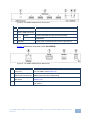
Figure 2 defines the rear panel of the VA-1USB-T.
Figure 2: VA-1USB-T USB Transmitter Rear Panel
#
Feature
Function
6
USB HOST INPUT
Type B USB Connector
Connect to a USB host (see Section 5)
7
CAT 5/6 OUT RJ-45
Connector
Connect to the CAT 5/6 IN RJ-45 connector on the VA-1USB-R
(see Section 2.4)
8
MACHINE ID 4-way
DIP-switch
Use to set the device ID to pair with the receiver (see Section 5.2)
9
5V DC Power Connector
Connect to one of the supplied +5V DC power adapters. Center
pin positive
4.2
Defining the VA-1USB-R USB Receiver
The VA-1USB-R decodes the USB signal and RS-232 data from the TP link sent
from the VA-1USB-T. The receiver distributes the USB signal across four USB
ports (acting as a USB hub) and outputs the RS-232 data. The VA-1USB-R
receives an IR signal via its IR sensor and sends it over the TP link to the
VA-1USB-T.
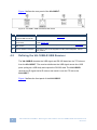
Figure 3 defines the front panel of the VA-1USB-R.
6
VA-1USB-T/VA-1USB-R - Defining the VA-1USB-T and VA-1USB-R USB Transmitter and
Receiver