1
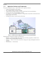
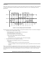
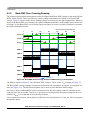
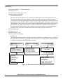
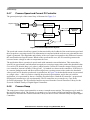
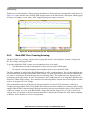
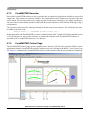
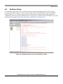
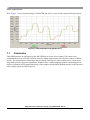
Software Design
Further correct functionality of the proposed mechanism is documented in experimental results with notes
in Figure 5-8, where the blue and red traces are Back-EMF, and the green trace is Dual Timer CH0 output,
which toggles its state on a compare event.
Condition accomplished
Fast interrup t function
switched to
IsrAdcStartRead
IsrAdcBlock
- testing selected bemf on
condition 20%-80% of vDcb
Zero crossing detected
Multisampling stopped
Calculation of time from zero crossing
to commutation performed
IsrAdcStartRead
- multisampling technique
- zero crossing evaluation
IsrCommutationTimer
- increment sector
- update mask and software control of PWM module
- select proper bemf channel
- change fast interrupt function to IsrAdcBlock
- set Dual timer Ch0 to triggered mode
Figure 5-8. Practical Description of Zero Crossing, Commutation, and Back-EMF Testing
5.7
FreeMASTER Software
The FreeMASTER software is designed to provide a debugging, diagnostic, and demonstration tool for
the development of algorithms and applications. It is also useful for tuning the application for different
power stages and motors. Almost all the application parameters can be changed via the FreeMASTER
interface. This consists of a component running on a PC and another part running on the target DSC
connected via an RS-232/USB port. A small program, resident in the DSC, communicates with the
FreeMASTER software to parse commands, return status information to the PC, and processes control
information from the PC. FreeMASTER software is executed on the PC using Microsoft Internet Explorer
as the user interface.
NOTE
For the correct functioning of the RS-232/USB connection,
HC9S08JMxx.inf driver must be previously installed on the PC and the
respective COM port must be selected in the FreeMASTER Project/Options
menu.
BLDC Sensorless Reference Design Using MC56F8006, Rev. 0
5-12
Freescale Semiconductor