1
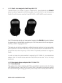
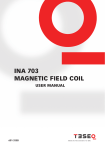
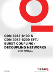
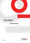
®
E stablished 1981
Advanced Test Equipment Rentals
www.atecorp.com 800-404-ATEC (2832)
1
manually or automated magnetic field
options mfo 6501 and
mfo 6502
user manual
601-318A
manuAlly or automated magnetic field
options MFO 6501 and
MFO 6502
User manual
MFO 6501 and MFO 6502
contents
1
Explanation of symbols
2
Safety instructions
2.1General
3
Magnetic Fields Option MFO 6501 and MFO 6502
3.1
General description
3.2
Manual Magnetic Field Option MFO 6501
3.2.1 Circuit diagram MFO 6501
3.2.2 MFO 6501 description
3.2.3 Parts description
3.2.4Installation
3.2.5 Standard operation – adjustments
3.3
Automatic Magnetic Field Option MFO 6502
3.3.1Introduction
3.3.2 Circuit diagram MFO 6502
3.3.3 MFO 6502
3.3.4 Parts description
3.3.5 Installation - connection to NSG
3.3.6 Technical specifications
4Accessories
4.1
Magnetic field loops
4.1.1 Single-turn magnetic field loo INA 701
4.1.2 Multi-turn magnetic field loop INA 702
4.2
Pulse wave shape adapter INA 752
4.2.1Introduction
4.2.2 Generator setting
5
Maintenance and function check
5.1General
5.2Cleaning
Function check
5.3
5.4Calibration
5.5Warranty
6
CE conformity
7Addresses
5
6
4
8
8
8
10
10
11
11
12
12
12
14
15
15
16
17
19
19
19
20
20
20
21
22
22
22
22
23
23
24
26
1 eXplanation of symBols
Please take note of the following explanations of the symbols used in order
toachievetheoptimumbenefitfromthismanualandtoensuresafetyduring
operation of the equipment.
The following symbol draws your attention to a circumstance where nonobservation of the warning could lead to inconvenience or impairment in the
performance.
Example:
This connection must not be confused with the Equipment
under Test (EUT) power input.
The following symbol draws your attention to a circumstance where nonobservation of the warning could lead to component damage or danger to the
operating personnel.
Example:
Never connect or disconnect the EUT while the test
system is performing a test.
5
6
2 safety instructions
These operating instructions form an essential part of the equipment and must
be available to the operator at all times. The user must obey all safety instructions
and warnings.
Neither Teseq AG, Luterbach, Switzerland, nor any of its subsidiary sales organizations can accept any liability for personal, material or consequential injury, loss or
damage that may result from improper use of equipment and accessories.
2.1 General
The MFO with its NSG and other accessories must be operated only by authorized
and trained specialists.
Theunitistobeusedonlyforthepurposespecifiedbythemanufacturer.Theuser
is directly responsible for ensuring that the test setup does not cause excessive
radiated interference which could affect other instrumentation.
The test system itself does not produce any excessive EM radiation. However, the
injectionofcurrentintoaloopresultsinaradiatingelectromagneticfield.
To avoid unwanted radiation, the standards organizations recommend that the test
setup be operated inside a Faraday cage.
Danger of radiating illegal electromagnetic interference.
The NSG 3040/3060 with its MFO may only be installed
and used by authorised and trained EMC specialists.
The NSG 3040/3060 with its MFO must only be used for
EMC tests.
MFO 6501 and MFO 6502
Personnel fitted with a heart pacemaker must not
operate the instrument and must not be in the vicinity
of the test rig while it is in operation.
Please take note of the following explanations of the symbols used in order to
achieve the optimum benefit from this manual and to ensure safety during operation of the equipment.
It is recommended for the user to stay away (at least a
few meters) from the loop antenna while magnetic field
is generated. Also keep away magnetic field sensitive
devices such as credit cards – magnetic key cards etc…
which might be influenced by the field.
7
8
3 magnetic field option mfo 6501
and mfo 6502
3.1 General description
Mainsfrequencymagneticfieldssimulatethekindofstrayfieldsthatoccuraround
current carrying power supply lines.
MFO6501isamanuallydrivenmagenticfieldoptionwhiletheautomaticdriven
MFO6502isdrivenbytheNSG3040orNSG3060generator.BothMFO’sfullfillsthe
specificationinaccordancewiththeIEC61000-4-8standardbyinducingastrong
currenttoflowinamagneticfieldloop.
3.2 Manual Magnetic Field Option MFO 6501
The manual operated current generator type MFO 6501 is a standard accessory to
generatesinconjuctionwithamagneticloopamagneticfield.
MFO 6501 and MFO 6502
The MFO 6501 provides a convenient means of generating and adjusting the current
to flow through one of the magnetic field loops, like INA 701 or INA 702 (see acces.
sories). It is required for magnetic field testing for fields up to 40 A/m. It complies
with the requirements of IEC 61000-4-8. It can be used as a stand alone instrument
It is fitted with carrying handles as part of its overall good ergonomic design, which
makes for ease of handling. Further, the unit may be used in any of three operating
positions; laying or standing on a work bench, or for more permanent applications,
it can be wall mounted.
Care has to be taken is case of use in standing position, as the stability is limited, so the cabling connecting
MFO 6501 to mains presents a risk of being unvoluntarly
caught by the users causing the MFO 6501 to fall down.
The few control elements are readily accessible on the front panel. A rotary hand –
wheel to set the necessary current, a 50 – 60 Hz frequency selector and a low – high
range selector ensure easy and intuitive operation.
Two safety banana sockets provide a convenient means to connect the loop
antenna, two other ones (shorted by a delivered shunt) to connect an external ampmeter to monitor the generated field, as the field generated in the loop antenna is
directly proportional to the current flowing through it:
H = Cf x I
Where H is the generated field, Cf the coil factor, I the current flowing through
the loop.
The unit has been designed for use in rugged industrial environments. Professional
quality connectors ensure user safety, additional system protection is provided by
a temperature sensor located on the heatsink of the power amplifier.
MFO 6501 is designed to drive INDUCTIVE LOADS ONLY,
as magnetic field loops. CONNECTING CAPACITIVE
LOADS WILL DESTROY THE INSTRUMENT.
9
10
3.2.1 Circuit diagram MFO 6501
Mains
input
Red
Power supply
+ 15 V, 0 V, -15 V
Black
Power amplifier
Sine wave
Signal generator
50 Hz
60 Hz
Amplitude
setting
Low
High
3.2.2 MFO 6501 description
2
3
4
5
6
1
MFO 6501 and MFO 6502
3.2.3 Parts description
11
Parts designation
Function
1
Mains supply in socket
For instrument supply, includes plug,
On/Off switch and 3,15 AT fuse
2
2 Output control potentiometer
For output level adjustment
3
Range select switch
To switch from high range to low
range – low range allows finer tuning
for low amplitude current generation
4
Freq. Select switch
To switch from 50 to 60 Hz
5
Green safety banana sockets
For external amp-meter connection
6
Power out – red and black
banana sockets
For connection to magnetic field loop
antennas INA 701 or INA 702
3.2.4 Installation
The equipment should be switched off during installation and interconnection.
Connect MFO 6501 to the lopp (INA 701 or 702). In case of use of
INA 702 insure that “power“ plug is fitted, see description of the
accessories.
Connect MFO 6501 to mains
Connect external amp-meter
Switch ON mains power
Adjust the required current through the loop using hand-wheel
12
3.2.5 Standard operation - adjustments
The field generated in the loop antenna is directly proportional to the current flowing
through it.
Standard Field in the loop
level
A/m
Current required for
INA 701 Cf = 0,89
Loop antenna
702; Cf 9,8
1
1
1,12 A
0,102 A
2
3
3,37 A
0,306 A
3
10
N/A
1,02 A
4
30
N/A
3,06 A
x
40 (max)
N/A
4,08 A
Use the external amp-meter to adjust the required current
3.3 Automatic Magetic Field Option 6502
3.3.1 Introdution
The automatic type MFO 6502 (Magnetic Field Option) is a standard accessory for
the Teseq NSG 3000 generator series. It provides a convenient means of generating and regulating the current to flow through one of the magnetic field loops. It
is required for magnetic field testing for fields up to 40 A/m. It complies to the
requirements of IEC 61000-4-8.
It is fitted with carrying handles as part of its overall good ergonomic design, which
makes for ease of handling. Further, the unit may be used in any of two operating
positions; laying on a work bench, or for more permanent applications, it can be
wall mounted.
MFO 6501 and MFO 6502
13
Its control is fully automatic, driven from NSG 3040 or NSG 3060 or WIN 3000. Once
detected, the functions offered by MFO 6502 are available in the user interface
or in the WIN 3000 software. As the voltage to A/m ration factor of the used loop
antenna is available in the user interface or WIN 3000, the user will setup his tests
directly in A/m, the software makes the calculation and drives the MFO 6502 to
generate the right current through the loop antenna.
Two safety banana sockets (red and black) provide a convenient means to connect
the loop antenna, Two other ones (Gree – shorted by a delivered shunt) to connect
an external amp-meter to verify (or to calibrate) the generated current, as the field
generated in the loop antenna is directly proportional to the current flowing through
it:
H = Cf x I
Where H is the generated field, Cf the coil factor, I the current flowing through
the loop.
The unit has been designed for use in rugged industrial environments. Professional
quality connectors ensure user safety, additional system protection is provided by
a temperature sensor located on the heatsink of the power amplifier.
14
MFO 6502 is designed to drive INDUCTIVE LOADS ONLY,
as magnetic field loops. CONNECTING CAPACITIVE
LOADS WILL DESTROY THE INSTRUMENT.
For proper operation of the plug and play detection mechanisms it is strongly recommended to power on first the
MFO 6502 accessory and then the NSG generator main
frame.
Powering on the NSG main frame before the accessories
may result in a non detection of the accessories.
3.3.2 Circuit diagram MFO 6502
Mains
input
Red
Power supply
+ 15 V, 0 V, -15 V
Black
Power amplifier
Sine wave
Signal generator
50 Hz
60 Hz
Amplitude
control
Low/High
range
Controller
Plug X1 – System cable IN
25 Way Sub D - Male
Plug X2 – System cable OUT
25 Way Sub D - Female
Connection to NSG master
controller via system interface
cable
Termination with NSG Interlock
plug
MFO 6501 and MFO 6502
3.3.3 MFO 6502
15
2
3
3
2
6
7
5
4
1
3.3.4 Parts description
Part designation Function
1 Mains supply In socket For instrument supply, includes plug,
On/Off switch and 3,15 AT fuse
2 Green safety banana sockets For external amp-meter connection
3 Power Out – red and black For connection to magnetic field loop
banana sockets
antennas INA 701 or INA 702
4 Plug X2 NSG system interface OUT – to be
terminated by Modula Interlock plug or
linked to another accessory, to X1 plug
5 Plug X1 NSG system Interface IN – to be con
nected to Modula Master Controller or
to another accessory, to X2 plug
6 Power LED Shows if instrument is powered up
7 Error LED
ERROR LED off:
No problem – accessory is ready to
run
ERROR LED blinking:
Problem able to be solved by user. Ex:
16
Interlock is activated – emergency
button is pressed – overtemperature
(for MFO 6502)
ERROR LED On:
Problem which needs module repair – please contact your nearest Teseq
customer support center or sales
representative.
3.3.5 Installation - connection to NSG
The equipment should be switched off during installation and interconnection.
Connect instrument power IN to mains
Remome 25 way Sub D plug at rear of NSG Master Controller
Connect this connector to X2 of MFO 6502
Connect 25 way output to MFO 6502 X1 plug, using system interface cable
delivered with MFO 6502
Connect MFO 6502 to loop antenna INA 701 or 702
In case of INA 702, verify that “Power“ plug is fitted
Power On MFO 6502
Power On NSG main frame
MFO 6501 and MFO 6502
3.3.6 Technical specifications
17
Parameter
MFO 6501
MFO 6502
Magnetic field
adjustment
Manually via potentiometer
Software driven via
user interface or WIN
3000
Dimensions
195 x 180 x 380 mm
Weight
4 kg approx.
Connections
Mains supply In Socket
4,2 kg approx.
Sockets for DVM
Power out safety banana sockets
n.a.
Plug X1, 25 way sub D
connected to NSG
n.a.
Plug X2, 25 way sub D
ermination plug
Control cable
n.a.
2 meters – 25 way
sub D – twisted pair
– shielded (incl. in
delivery) to connect to
NSG
Supply voltage
90 to 240 V
Power consumption
< 150 W
Operating temperature
5° – 40° C
Overload protection
By temperature sensor on power stage
Total harmonic
distortion (THD)1
< 8% (nominal <3,5 % at full range)
Frequency
Selectable 50 and 60 Hz +/- 3%
18
Range selection
Loop antenna INA
701; Cf 0,89
Loop antenna 702;
Cf 9,8
Range low 2
80 to 400 mA into
INA 701 allows 0,08
to 0,36 A/m
80 to 400 mA into
INA 702 allows 0,8
to 4 A/m
Range high 2,3
200 mA to 4,1 A into
INA 701 allows 0,18
to 3,6 A/m
200 mA to 4,1 A into
INA 702 allows 2
to 40 A/m
Typical, for the full range from standard level 1 (lowest standard level) to full range
(level X)
1
2
Current adjustment through customer provided amp-meter for MFO 6501.
3
Current adjustment – software driven for MFO 6502
Indicated max values reachable for environmental temperatures below 30°C. For
higher environment temperatures internal temperature sensor might trip after a
few minutes.
MFO 6501 and MFO 6502
4 accessories
4.1Magneticfieldloops
Whentestswithmainsfrequencyand/orpulsedmagneticfieldsneedtobeperformed,Teseqprovidestwodiffernmagneticfieldloops.Thesearerectangular
loops measuring 1 x 1 m and are suitable for test objects with dimensions up to
0.6x0.6x0.5m.Twotypesofloopcanbesupplied,INA701andINA702.
4.1.1Single-turnmagneticfieldloopINA701
TheINA701isa1x1mloop–singleturn-withacoilfactorof0.89.Itenables
thegenerationoffieldstrengthsofupto3,6A/mformainsfrequencyfields50or
60HzwhenusedwiththeMFO6501orMFO6502currentsourcesand1200A/m
forpulsedmagneticfields(IEC61000-4-9),wherethecurrentisgeneratedbya
4400 V surge generator.
19
20
4.1.2 Multi-turn magnetic field loop INA 702
The INA 702 is a 1 x 1 m loop - 11 turns – coil factor 9,8 - when fitted with the POWER
plug. It enables the geration of field strengths of up to 40 A/m for mains frequency
fields 50 or 60 Hz when used with the MFO 6501 or MFO 6502 current sources.
INA 702 becomes a single turn loop when fitted with the PULSE plug, which allows
the generation of pulsed field strengths up to 1200 A/m, where the current is generated by a 4400 V surge generator.
The tests are carried out using the so-called immersion method, i.e. the item under
test is placed in the center of the loop. The test is performed in accordance with the
IEC 61000-4-8 (mains frequency) or IEC 61000-4-9 (pulsed) standards for magnetic
fields.
In order to meet the pulse waveform required by IEC 61000-4-9, the waveshape
adapter INA 752 needs to be used with NSG 3040 and the INA 701 or 702 loop
antennas.
4.2 Pulse wave shape adapter INA 752/INA 753
4.2.1 Introduction
The pulse wave shape adapter INA 752 is a standard accessory for the Teseq
NSG 3040 generator, resp. INA 753 for NSG 3060. It provides a convenient means
of interconnecting the surge generator pulse output with the loop antennas INA
MFO 6501 and MFO 6502
701 or 702 and insures that the generated pulsed has the wavshape as specified
in the application standard IEC 61000-4-9.
4.2.2 Generator setting
Generally surge generators get setted by voltage, the current they deliver will
depend from the load impedance. In this case the load consists in the loop antenna
plus the waveshape adapter which is fix and stable. So there is a direct relationship
between the generator voltage setting and the current delivered to the load.
As there is also a direct relationship between current in the loop antenna and the
generated field (coil factor), there will be a direct relationship between the surge
generator setted voltage and the generated field.
The coilfactor is given by the loop antenna manufacturer. It consists in the value
englobing the factor of the coil plus the factor of the pulse waveshape adapter.
This global factor is labelled on the INA 752 or INA 753 pulse waveshape adapter.
In case of use with Teseq INA 702 loop antenna, insure that termination plug labelled
PULSE is fitted on antenna.
To make the use easy, Teseq provides directly the Volts to A/m ratio. This one is
indicated on the top panel of the INA 752/753. This ratio has to be entered in the
user interaface screen or WIN 3000 in order to generate the right field. The user
will then always enter his settings in Amps / meter.
Volts to A/m ratio: This factor has to be entered in the software in the field “coilfactor”.
In case a INA 702 loop antenna is used, the termination plug
labelled “Pulse“ needs to be used.
21
22
5 maintenance and function
cHecK
5.1 General
Inside the test system there are no adjustable elements accessible to the user for
either calibration or maintenance purposes.
The housing of the test system must not be opened. Should any maintenance or
adjustment become necessary, the whole test system, together with an order or
fault report, should be sent in to a Teseq service center.
Maintenance by the user is restricted to cleaning the outer housing, performing a
functioncheckandverificationofthepulseparameters.
5.2 Cleaning
Ingeneralamoistclothissufficientforcleaningtheouterhousing.Instubborn
cases use a small amount of a mild, non-foaming household cleanser as well.
No chemicals should be used for cleaning purposes.
Before beginning to clean the test system ensure that it is switched off and the
mains power cable is unplugged from the supply.
5.3 Function check
The safety measures described previously must be
strictly observed while carrying out a function check.
MFO 6501 and MFO 6502
As soon as the test system is switched on the Power-LED should light up. If this is
not the case then please check the mains power connection to the test system as
well as the fuses, voltage selector and any other cabling.
The instrument automatically carries out a diagnostic routine once it has been
successfully switched on.
The generator cannot perform any test while the Interlock circuit is open.
5.4 Calibration
The combination of high voltages and high frequencies in a single pulse makes the
calibration of EMC pulse generators particularly demanding and difficult. Teseq
has one of the few accredited test laboratories in Europe that is in the position to
undertake calibrations in this specialized field.
5.5 Warranty
Teseq grants a warranty of two years on this test system, effective from the date
of purchase.
During this period, any defective components part will be repaired or replaced free
of charge or, if necessary, the test system will be replaced by another of equivalent
value. The decision regarding the method of reinstating the functional capability is
at the sole discression of Teseq.
Excluded from the warranty is damage or consequential damage caused through
negligent operation or use as well as the replacement of parts subject to degradation.
The warranty is rendered invalid by any intervention on the part of the customer
or a third party.
The faulty items are to be returned in their original packaging or other equivalent
packaging suitable for the purpose of the foreseen means of transportation.
Teseq can accept no responsibility for damage in transit.
23
24
6 ce conformity
TheequipmentisCE-certificated.Thefollowingstandardsapply:
Type of standard Standard nr. Remark
EN 61010
Safety requirements for electrical equipment for use in measurement, control,
regulation and laboratory applications.
Generic standard
EN 61000-6-3
Electromagnetic compatibility (EMC);
generic standard for interference radiation; Part 6.3 for residential, business
and trade applications as well as small
businesses.
Generic standard
EN 61000-6-4
Electromagnetic compatibility (EMC);
generic standard for interference radiation; Part 6.4 industrial applications.
Generic standard
EN 61000-6-1
Electromagnetic compatibility (EMC);
generic standard for interference
immunity; Part 6.1 for residential, business and trade applications as well as
small businesses.
Generic standard
EN 61000-6-2
Electromagnetic compatibility (EMC);
generic standard for interference immunity; Part 6.2 for industrial applications.
Product family
standard
EN 60326-1
Electrical equipment for measurements, control and laboratory use.
Product family
standard
MFO 6501 and MFO 6502
The requirements cannot be fulfilled in some cases. (The true purpose of an
interference generator is to produce interference signals. Emission limitations can
therefore only be complied with if the equipment is operated inside a faraday cage).
Deviations from the requirements are stated and explained in the appendix to the
conformity declaration.
25
Headquarters
Teseq AG
4542 Luterbach, Switzerland
T + 41 32 681 40 40
F + 41 32 681 40 48
sales @ teseq.com
www.teseq.com
Manufacturer
Teseq AG
4542 Luterbach, Switzerland
T + 41 32 681 40 40
F + 41 32 681 40 48
sales @ teseq.com
China
Teseq Company Limited
T + 86 10 8460 8080
F + 86 10 8460 8078
chinasales @ teseq.com
France
Teseq Sarl
T + 33 1 39 47 42 21
F + 33 1 39 47 40 92
francesales @ teseq.com
Germany
Teseq GmbH
T + 49 30 5659 8835
F + 49 30 5659 8834
desales @ teseq.com
Japan
Teseq K.K.
T + 81 3 5725 9460
F + 81 3 5725 9461
japansales @t eseq.com
Singapore
Teseq Pte Ltd.
T + 65 6846 2488
F + 65 6841 4282
singaporesales @ teseq.com
Switzerland
Teseq AG
T + 41 32 681 40 50
F + 41 32 681 40 48
sales @ teseq.com
Taiwan
Teseq Ltd.
T + 886 2 2917 8080
F + 886 2 2917 2626
taiwansales @ teseq.com
UK
Teseq Ltd.
T + 44 845 074 0660
F + 44 845 074 0656
uksales @ teseq.com
USA
Teseq Inc.
T + 1 732 417 0501
F + 1 732 417 0511
Toll free +1 888 417 0501
usasales @ teseq.com
© December 2010 Teseq®
Specifications subject to change
without notice. Teseq® is an ISOregistered company. Its products are
designed and manufactured under
the strict quality and environmental
requirements of the ISO 9001. This
To find your local partner within document has been carefully checked.
Teseq®’s global network, please go to However, Teseq® does not assume
www.teseq.com
any liability for errors or inaccuracies.