1
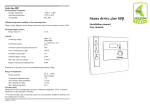
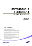
LOTOS TECHNOLOGY
Plasma Cutter LTP5000D
www.uwelding.com
®
Lotos Technology LTP5000D
Quick Setup
Instructions
Power plug wiring identification:
For either 110 or 220VAC, the GREEN wire with the yellow strip is ground wire. The other two
wires are hot wires.
1. Wear a proper helmet (Figure 1.1) to protect your eyes from
harmful plasma cutting arc radiation. Wear safety gloves to
protect your hands during operation.
Figure 1.1
2. Connect the machine gas inlet (on the back of the machine, Figure 1.2) to an air compressor
(Figure 1.3 & 1.4) and set the air pressure to 65 - 70 PSI. (The air regulator is optional as some air
compressors provide air pressure control capability).
65 - 70 PSI
Figure 1.3
Gas
Inlet
Power
Cord
Gas
Inlet
Figure 1.2
Output
from
Air
Compressor
Figure 1.4
®
1
3. Connect your plasma cutting torch and ground cable to the front panel of the machine
(Figure 1.5) .
Switch
Plug
Cutting
Torch
& Air
Pilot Arc
Connection
Ground
Cable
Figure 1.5
4. Attach the ground clamp to the metal work piece that you plan to cut. Grind the metal to make
sure the clamp is securely attached. Press the trigger of the torch and make sure there is air
flow. Finally, move the torch head to the work piece and enjoy cutting!!
5. Change your consumables (tip, electrode, and cup) when they become worn out. The correct
consumable type is PCON. The metal protector on the tip is also replaceable. All accessories and
consumables can be purchased at www.uwelding.com or Lotos’s authorized resellers.
Thank you for your business!
LOTOS Plasma Cutters
User Manual
Version: 2.0, May 2014
copyright @ Lotos Technology
www.uwelding.com is operated by Lotos Technology
®
Table of Contents
Introduction 3
Overview . . . . . . . . . . . . . . . . . . . . . . . . . . . . . . . . . . . . . . . . . . . . . . . . . . . . . . . . . . . . . . . . . . . . . . . . . . . . . . . . 3
Audience . . . . . . . . . . . . . . . . . . . . . . . . . . . . . . . . . . . . . . . . . . . . . . . . . . . . . . . . . . . . . . . . . . . . . . . . . . . . . . . . 3
Safety Precautions
4
Overview . . . . . . . . . . . . . . . . . . . . . . . . . . . . . . . . . . . . . . . . . . . . . . . . . . . . . . . . . . . . . . . . . . . . . . . . . . . . . . . . .
Caution Recommendations . . . . . . . . . . . . . . . . . . . . . . . . . . . . . . . . . . . . . . . . . . . . . . . . . . . . . . . . . . . . . . . . .
Avoiding Fatal Electric Shock . . . . . . . . . . . . . . . . . . . . . . . . . . . . . . . . . . . . . . . . . . . . . . . . . . . . . . . . . . . . . . . .
Avoiding Harmful Smoke, Gases, and Vapors . . . . . . . . . . . . . . . . . . . . . . . . . . . . . . . . . . . . . . . . . . . . . . . . .
Avoiding Harmful Arc Emissions/Rays . . . . . . . . . . . . . . . . . . . . . . . . . . . . . . . . . . . . . . . . . . . . . . . . . . . . . . .
Avoiding Harmful Noises . . . . . . . . . . . . . . . . . . . . . . . . . . . . . . . . . . . . . . . . . . . . . . . . . . . . . . . . . . . . . . . . . . .
Fire or Explosion . . . . . . . . . . . . . . . . . . . . . . . . . . . . . . . . . . . . . . . . . . . . . . . . . . . . . . . . . . . . . . . . . . . . . . . . . .
Burn Protection . . . . . . . . . . . . . . . . . . . . . . . . . . . . . . . . . . . . . . . . . . . . . . . . . . . . . . . . . . . . . . . . . . . . . . . . . . .
Protecting Eyes from Flying Metal or Dirt . . . . . . . . . . . . . . . . . . . . . . . . . . . . . . . . . . . . . . . . . . . . . . . . . . . . .
Pacemakers . . . . . . . . . . . . . . . . . . . . . . . . . . . . . . . . . . . . . . . . . . . . . . . . . . . . . . . . . . . . . . . . . . . . . . . . . . . . . .
Cylinder Handling . . . . . . . . . . . . . . . . . . . . . . . . . . . . . . . . . . . . . . . . . . . . . . . . . . . . . . . . . . . . . . . . . . . . . . . . .
4
4
4
4
4
4
5
5
5
5
5
Equipment 6
Description . . . . . . . . . . . . . . . . . . . . . . . . . . . . . . . . . . . . . . . . . . . . . . . . . . . . . . . . . . . . . . . . . . . . . . . . . . . . . . . 6
Main Characteristics . . . . . . . . . . . . . . . . . . . . . . . . . . . . . . . . . . . . . . . . . . . . . . . . . . . . . . . . . . . . . . . . . . . . . . . 6
Product Specifications . . . . . . . . . . . . . . . . . . . . . . . . . . . . . . . . . . . . . . . . . . . . . . . . . . . . . . . . . . . . . . . . . . . . . . 6
Adjustor Diagram . . . . . . . . . . . . . . . . . . . . . . . . . . . . . . . . . . . . . . . . . . . . . . . . . . . . . . . . . . . . . . . . . . . . . . . . . . 9
Power Cord Plug Connection . . . . . . . . . . . . . . . . . . . . . . . . . . . . . . . . . . . . . . . . . . . . . . . . . . . . . . . . . . . . . . . 9
Connecting Cables to Machine. . . . . . . . . . . . . . . . . . . . . . . . . . . . . . . . . . . . . . . . . . . . . . . . . . . . . . . . . . . . . . 10
Installations . . . . . . . . . . . . . . . . . . . . . . . . . . . . . . . . . . . . . . . . . . . . . . . . . . . . . . . . . . . . . . . . . . . . . . . . . . . . . . 11
Instruction Notes 13
Cutting Environment . . . . . . . . . . . . . . . . . . . . . . . . . . . . . . . . . . . . . . . . . . . . . . . . . . . . . . . . . . . . . . . . . . . . . . 13
Safety . . . . . . . . . . . . . . . . . . . . . . . . . . . . . . . . . . . . . . . . . . . . . . . . . . . . . . . . . . . . . . . . . . . . . . . . . . . . . . . . . . . 13
Notes for Torch . . . . . . . . . . . . . . . . . . . . . . . . . . . . . . . . . . . . . . . . . . . . . . . . . . . . . . . . . . . . . . . . . . . . . . . . . . . 13
Maintenance and Troubleshooting . . . . . . . . . . . . . . . . . . . . . . . . . . . . . . . . . . . . . . . . . . . . . . . . . . . . . . . . . . 13
Trouble Shooting Guide . . . . . . . . . . . . . . . . . . . . . . . . . . . . . . . . . . . . . . . . . . . . . . . . . . . . . . . . . . . . . . . . . . . . 14
Plug Wiring Instructions . . . . . . . . . . . . . . . . . . . . . . . . . . . . . . . . . . . . . . . . . . . . . . . . . . . . . . . . . . . . . . . . . . . . 15
For more information and more of our products,
please visit our website at
http://www.uwelding.com/
Introduction
Overview
Dear Valued Customer:
Thank you for purchasing a Lotos Technology plasma cutter! Feel free to check out our other products at
www.uwelding.com.
The User Manual documents policies and procedures for proper operation of the equipment.
IMPORTANT: Be sure to review the contents of this manual before attempting to operate the equipment.
This manual should be located where it can be easily referenced by all users of the machine.
Audience
This manual assumes that all individuals reading the manual and using the welder/cutter are able,
qualified, and/or certified to operate this type of machinery.
®
3
Safety Precautions - Read Before Using
Overview
Protect yourself and others from injury — read and follow these precautions.
Caution
Recommendations
CAUTION: Welding and arc cutting
can cause bodily injury.
• Do NOT switch off the machine while machine is
in operation or internal circuitry can be damaged.
Avoiding Fatal Electric Shock
• Isolate yourself from both the
earth and the work piece.
• Connect the machine to a UL-approved outlet
only. Do not hard wire the machine directly to the
power source.
• Wear safety goggles at all times. This will darken
the arc that is generated by the machine and
protect your eyes from harmful rays.
• All machine operators should be technically
certified for welding/cutting.
• Make sure that your working area is nonflammable
and explosive-free.
Avoiding Harmful Smoke, Gases, and Vapors that can injure or kill.
Welding produces fumes and gases.
Breathing these fumes and gases can
be hazardous to your health.
• Keep your head away from any smoke, gases,
or vapots.
• Make sure that gases are flowing away from
Avoiding Harmful Arc Emissions/Rays that can burn eyesyou
and
to skin.
avoid breathing in the gases.
Arc rays from the welding process
produce intense visible and invisible
rays that can burn eyes and skin.
Sparks fly off from the weld.
• Wear appropriate clothing and a welding or
cutting mask to protect your eyes and skin.
• Use appropriate screen or curtain to prevent
emissions from reaching individuals near the
work area.
• Ensure that your working area contains no
flammable items and that none are nearby.
Caution: Welding and cutting spray can ignite.
Avoiding Harmful Noises that can damage hearing.
Noise from some processes can
damage hearing.
• Wear protective earplugs while operating
machine.
®
4
Welding or Cutting can cause Fire or Explosion.
Welding, cutting, and allied
processes can cause fire or
explosion if precautionary
measures are not followed.
• Develop adequate procedures and use proper
equipment to do the job safely.
• Remove combustible materials from a sphere
with a minimum radius of 35 feet around the
work area or move the work to a location well
away from combustible materials.
Burn Protection: HOT PARTS can cause serious burns.
The work piece and equipment
get hot. The hot metal, hot work
piece, and hot equipment can
cause burns.
• Use approved helmets or hand shields that
provide protection for the face, neck, etc.
• Wear approved safety goggles or glasses with
side shields, even under your helmet.
• Wear dry, hole-free insulated gloves.
Protect eyes from FLYING METAL or DIRT.
• Welding, chipping, wire
• Wear approved safety glasses with side shields,
brushing, and grinding cause
even under your welding helmet.
sparks and flying metal.
PACEMAKERS AND
WELDING: MAGNETIC FIELDS can affect implanted devices.
Electric arc welding and cutting
processes produce intense electric
and magnetic (electromagnetic)
fields. The function of pacemakers
can be affected by strong
electromagnetic fields.
• Persons with a pacemaker should not go near
welding or cutting operations until they have
consulted their doctors and obtained information
from the manufacturer of the device.
Shielding gas cylinders contain gas
under high pressure. If damaged,
a cylinder can explode. Be sure to
treat gas cylinders carefully.
• Protect compressed gas cylinders from excessive
heat, mechanical shocks, physical damage, slag,
open flames, sparks, and arcs.
• Install cylinders in an upright position by securing
to a stationary support or cylinder rack to prevent
falling or tipping.
CYLINDER HANDLING: it can explode if damaged.
• Keep cylinders away from any welding or other
electrical circuits.
If you encounter any difficulties during set up or operation:
• Consult this manual.
• Contact Lotos Customer Service by visiting
http://www.uwelding.com/about-us/contact-us/.
Equipment
General Overview
The LTP5000D employs state of the art inverter technology. 50/60Hz frequency is inverted to high frequency
(over 100 KHz) by V-MOSFET followed by step down voltage and rectification current.
Using Pulse-Width-Modulation (PWM) technology, the inverter power supply generates powerful DC welding
currents. By applying switch power inverter technology, the dimensions and weight of the main transformer
is significantly reduced while efficiency is increased by 30%.
Main Characteristics
• Stabilization
• Reliability
• Portability
• Power efficiency and low noise output
• High cutting speed
• Smooth cuts
Suitable for stainless steel, alloy steel, mild steel, copper aluminum, and other metal materials;
there are many applications for plasma cutters.
Specifications
Input voltages
110-220V, 1-PH, 50/60 Hz
Input current
110-220V, 1-PH, 20 A
Output current
10-50 A
Duty cycle @ 40°C (104°F)
60% @ 50A, 110V
60% @ 50A, 220V
Dimensions with handle
15’’ (381mm) L; 6’’ (152.4mm) W; 12’’ (304.8mm) H
Weight w/ 8'11’’ (2.7 m) torch
22.5 lbs (10.2 kg)
Gas Supply
Clean, dry, oil-free air
Recommended gas inlet
flow rate / pressure
3.6 scfm @ 65 psi
Input power cable length
6’ (1.8 m)
Power supply type
Inverter - IGBT
Accessories
®
Pilot Arc Plasma Torch (9' 5")
Plasma Consumables (installed on the torch head)
Air Filter/Regtulator
Ground Clamp & Cable
Connections, (like Air Hose etc.)
User Manual
6
Torch Type
Torch Type
Model
3 prong LCON
cutting torch
Amperage
Consumable Type
50
LCON0120
LCON0140
LCON0190
CL0103
Extended 3 prong
LCON cutting torch
CL0203
50
PCON0120
PCON0140
PCON0190
Consumables Package
Part Number
Nozzle
Electrode
Shield Cup
Package Type
Total
Pieces
PCON0120
PN01
PE01
PC01
PN01 x 10,
PE01 x 10
20
PC01
PN01 x 15,
PE01 x 15,
PC01 x 10
40
90
PCON0140
PN01
PE01
PCON0190
PN01
PE01
PC01
PN01 x 35,
PE01 x 35,
PC01 x 20
PCON0220
PN02
PE02
PC02
PN02 x 10,
PE02 x 10
20
PCON0240
PN02
PE02
PC02
PN02 x 15,
PE02 x 15,
PC02 x 10
40
PC02
PN02 x 35,
PE02 x 35,
PC02 x 20
90
PCON0290
PN02
PE02
®
7
Production Cut Chart
Material
Mild
Steel
Stainless
Steel
Aluminum
Thickness*
Current
inches
mm
amps
10 gauge
3
50
1/4
6
50
3/8
10
50
1/2
12
50
5/8
16
50
10 gauge
3
50
1/4
6
50
3/8
10
50
1/2
12
50
1/8
3
50
1/4
6
50
3/8
10
50
1/2
12
50
*Production cut thickness are the results of Lotos’ laboratory testing.
Production speeds are approximately 80% of maximum.
For optimum cut quality, cutting speeds may vary based on different cutting applications.
®
8
Cutting
Current
Adjust
Cutting
Torch
& Air
Problem
Indicator
LED
Power
Switch
Switch
Plug
Pilot Arc
Connection
Power
Cable
Figure 2.1: Adjustor Diagram Ground
Connection
Gas
Inlet
Figure 2.2: Power Cord Plug Connection
Figure 2.3: Air Regulator Configuration
®
9
Ground
Air Compressor
Filter
Ground Clamp
Work
Piece
Torch
Figure 2.4: Connecting Cables to Machine
®
10
Installation
Power Cord Plug Connection (Figure 2.2)
1. Be sure to connect the power cord plug to the appropriate power voltage, and use a proper
hookup to avoid damage to internal circuitry. Typically, the ground wire is GREEN with a YELLOW stripe.
2. Ensure that the power cord is properly connected to the power switch to prevent oxidation.
Make sure the power voltage is within the specified safety range.
3. Please refer to the Plug Wiring Instructions of this manual for detailed instructions on plug
wiring.
Connecting the Cables to the Machine (Figure 2.4)
1. Properly connect the high pressure tube of pressed air to copper connector.
2. Ensure that copper screw at the opposite end of the torch is securely connected to the torch.
To avoid gas leakage, turn screw clockwise until it locks into position. Connect the mobile plug
at one end of the grounding cable pincer to the positive terminal located on the front panel;
and then tighten.
3. Ensure that the air plug of the torch is connected to the switch connector on the panel. For
cutters with pilot arc, connect the fork connector to the red terminal on the front panel.
Check-list before Operation
1. Ensure that the cutting machine is properly grounded.
2. Ensure that all connectors are connected appropriately and firmly.
3. Ensure that power voltages are correct.
Operating the Plasma Cutter
1. Make sure the machine on/off switch is in the off position. Plug the power cord plug into the
outlet.
2. Connect air compressor with air regulator/filter.
3. Connect the ground clamp to your work piece. Caution: Rust or paint on the work piece could
create an open circuit; therefore, the contact point should be cleaned thoroughly to ensure a
good connection between clamp and work piece.
4. Turn on the power switch. The cooling fan should start to operate and the LED should come
on. The front panel should show the machine’s electrical current volume, and you can adjust it
by turning the nob below the display.
®
11
Operating the Plasma Cutter
5. Adjust the air pressure on your air compressor to 60 – 65 psi for the machine.
6. Bring the torch tip into direct contact with your work piece edge or, for thicker cutting,
over a pre-drilled pilot hole. Press the button on the torch to start cutting.
7. Ensure that the cutting current is appropriate and adequate for the machine based on
the rated thickness of the cutter.
Note: Below is the consumable assembly on the torch head. (Figure 3.1)
Electrode
Cap
Nozzle
Torch
Figure 3.1
®
12
Instruction Notes
Cutting Environment
1. The cutting machine can perform in an environment where conditions are particularly harsh:
it can withstand outside temperatures between 14 and 104 degrees Fahrenheit and a humidity level
of up to 80%.
2. Please try to keep machine dry.
Safety
1. Working area MUST be adequately ventilated.
2. No over-load! Your machine can be damaged by over-loading.
3. No over-voltage! Internal circuitry can be damaged by over-voltage.
4. An internal heat-variable component is initialized if machine exceeds duty cycles. The cutting machine
will stop working immediately, and an internal red diode will be lighted. Note: The user does not need
to break the circuit; the fan will continue working in order to cool the machine. Once temperature is
reduced to allowable range, machine can be operated again.
Notes for Torch
1. Ensure that the copper tip is not in direct contact with the work piece while cutting. To protect copper tip, torch should be inclined and maintain a distance of 1 mm from inter-hole of copper tip to the work
piece.
2. If pilot arcing functions improperly, try to remove oxidization of the electrode on the torch with sand
paper.
Maintenance and Troubleshooting
1. Dust created by compressed air should be removed regularly. If work environment is polluted with
smoke and dust, daily maintenance is required.
2. Ensure adequate air pressure exists to protect internal components.
3. Check all connectors to ensure firm connections.
4. Protect machine from water or dampness.
5. When machine is not in use for a long period of time, it should be properly packed and stored in a dry
environment.
6. Replace any worn consumables to avoid damage.
®
13
The following trouble shooting guide is for your reference only. Lotos Technology will NOT take any
liability or responsibility for any injury or damage caused in such action(s). Always turn off electrical
power and air supply before performing inspection and reconnection.
CAUTIONS: Only qualified technicians are authorized to undertake the repair of this equipment in the
case of machine failure.
Faults
Possible Causes/Solutions
1. The power pilot light is off, 1. The power switch is broken.
the fan doesn’t work, and 2. There is no electrical power.
there is no cutting voltage 3. The input cable is short-circuited.
output.
2. The power switch is on,
the fan doesn’t work. No
voltage is indicated on the
front panel.
3. The fan is on, the
abnormal pilot light is not
on, cannot start the arc.
4. The abnormal pilot light is
off, no cutting voltage
output.
1. There is an improper connection to the plug or the plug is improperly
connected to the 380V power supply, causing over-voltage protection. For
latter case, wait for 8 minutes, reconnect to 220V power supply, and restart
the machine.
2. The transformer is broken.
3. Voltage deficiency protection has been activated.
4. The wire from the switch to the bottom board has loosened. Tighten it.
5. The relay on the bottom board is damaged. Replace with a new relay.
Contact the manufacturer or certified service personnel.
1. The welding cable is broken.
2. The ground is improperly connected to the work piece.
3. The “+” output terminal is not properly connected.
5. The problem pilot light is
not on.
1. The nozzle is oxidized or too far away. Remove the oxidization on
the surface, or shorten the distance to 1 mm.
2. Otherwise, contact the manufacturer or certified service personnel.
6. The abnormal pilot light is
on.
1. Over-current protection may have initialized. Either wait for 2 or
3 minutes for the problem to go away or turn off the power, wait until
the abnormal pilot light is off, and restart (machine will recover
automatically).
2. Otherwise, contact the manufacturer or certified service personnel.
7. The output current is not
stable.
8. The machine does not cut
metal properly, or the arc is
not stable.
1. Check connections on the front panel.
2. Otherwise, contact the manufacturer or certified service personnel.
1. The input voltage is too low.
2. The ground cable is not well-connected.
3. The air pressure is too high or too low.
4. The nozzle and electrode of the torch do not fit well, or the input
current is too low.
®
14
Plug Wiring
Instruction
Do not attempt to wire or handle high voltage without proper training. Contact an electrician to help you
install an electrical outlet or connect an electrical plug to your machine. Regardless of which machine you
have, it will require power to operate properly. Do not assume you know which wires to connect until you
read this manual completely as colors may be deceiving.
All of our machines are either 110VAC or 220VAC. The
110VAC machines will operate at 100V - 120VAC and
50-60Hz; the 220VAC machines will operate at
200-240VAC and 50-60 Hz. All machines are 1 phase
unless otherwise stated. 1 phase means the power
cord will have 1 ground wire and two hot wires
(Figure 4.1). Connecting these wires properly is very
important, and improper wiring could cause damage
and void product warranty.
Figure 4.1
The ground wires on most machines are dark green. Some of them are green with a yellow twisted line
in them. Some of the machines have blue, dark green, and dark red wires, and it may be difficult to
differentiate which wire is ground because the blue and dark green looks similar. The best way to test
for ground is to test the ohms between the machine chassis ground to the ground wire.
Note:
When ground wire is incorrectly connected, even the machine and the fan can turn on, but the machine
would not operate properly.
You may need to consult with an expert to find the proper plug for your machine. First you will need to
know the maximum amperage draw of your machine which should be in your manual. Write it down
and consult a qualified professional about which plug you will need.
The ground is the first wire you should connect in the
plug. Next connect the two live wires. Generally it
does not matter which one goes on which side. As a
general rule of thumb, connect blue on the left and
red on the right, or black on the left and white on the
right.
Figure 4.2
®
15
®