1
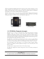
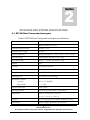
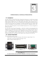
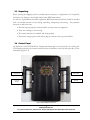
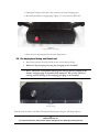
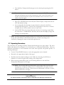
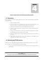
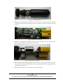
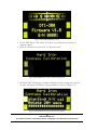
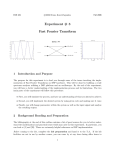
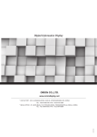
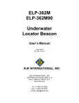
RJE INTERNATIONAL, INC.
DIVE-TRAK PRO
DIVER NAVIGATION SYSTEM
USER MANUAL
REV 1.0
Forward
This manual is comprised of figures and text intended to provide descriptions and
instructions for the deployment, operation, and maintenance of the RJE
International DIVE-TRAK PRO Diver Navigation System comprising the DTI-300
Diver Transponder Interrogator and the ATT-400 Acoustic Target Transponder. The
information herein is arranged into chapters and sections as follows:
Chapter 1 – An overview of the DTI-300. General notes including brief sections
describing the applications and physical characteristics of the Beacon itself.
Chapter 2 – Specifications. Sections comprised of lists of both general and uniqueto-the-unit specifications.
Chapter 3 – Operation and Deployment Notes. Sections detail the unpacking,
battery charging and predeployment checkout procedures for the DTI-300.
Chapter 4 - Maintenance. Sections detail periodic maintenance, battery replacement
and calibration procedures.
Appendices – Separate appendices contain mechanical and electrical drawings and
diagrams, parts lists, and integrated components list.
Please forward comments, questions, suggestions, or problems with the text,
figures, or equipment to RJE International.
ii
RJE International, Inc.
15375 Barranca Parkway, Suite B107, Irvine, CA 92618
Tel: (949)727-9399 Fax: (949)727-0070
E-mail: [email protected] Web Page: www.rjeint.com
PROPRIETARY MATERIAL
The descriptions, procedural information, photos, figures, drawings, illustrations, in this manual are the property
of RJE International, Inc. Materials may not be reproduced or disseminated without the prior written consent
of RJE International.
RJE International reserves the right to make changes in design or specifications at any time without incurring
any obligation to modify previously installed units.
This manual is provided for information and reference purposes only and is subject to change without notice.
LIMITED WARRANTY
RJE International, Inc. (FSI) guarantees its products to be free from defects in materials and
workmanship for a period of one year from the date of shipment. In the event a product malfunctions
during this period, FSI’s obligation is limited to the repair or replacement, at FSI’s option, of any product
returned to the FSI factory. Products found defective should be returned to the factory freight prepaid
and carefully packed, as the customer will be responsible for any damage during shipment.
Repairs or replacements, parts, labor, and return shipment under this warranty will be at no cost to the
customer. This warranty is void if, in FSI’s opinion, the product has been damaged by accident or
mishandled, altered, or repaired by the customer, where such treatment has affected its performance or
reliability. In the event of such mishandling, all costs for repair and return freight will be charged to the
customer. All products supplied by FSI that are designed for use under hydrostatic loading have been
certified by actual pressure testing prior to shipment. Any damage that occurs as a direct result of
flooding is NOT covered by this warranty.
If a product is returned for warranty repair and no defect is found, the customer will be charged a
diagnostic fee plus all shipping costs. Incidental or consequential damages or costs incurred as a result of
a product’s malfunction are not the responsibility of FSI.
Equipment not manufactured by FSI is supported only to the extent of the original equipment
manufacturers (OEM) original warranties. All OEM sensors that utilize electrodes (oxygen cartridges, pH,
ORP, etc.) are warranted at the time of shipment, and shall perform upon initial installation within stated
specifications. If the product proves to be defective within the OEM’s warranty, FSI will replace the
product or defective part with a similar model, product or part, but only to the extent that the OEM
warrants.
All returned products must be accompanied by a Returned Material Authorization (RMA) number issued by
FSI. Shipments without an RMA number will not be accepted.
LIABILITY
FSI shall not be liable for incidental or consequential damages, injuries, or losses as a result of the
installation, testing, operation, or servicing of FSI products.
iii
RJE International, Inc.
15375 Barranca Parkway, Suite B107, Irvine, CA 92618
Tel: (949)727-9399 Fax: (949)727-0070
E-mail: [email protected] Web Page: www.rjeint.com
RMA RETURN PROCEDURE
Before returning any equipment to FSI, you must contact FSI and obtain a Returned Material
Authorization (RMA) number. The RMA number assists FSI in identifying the origin and tracking the
location of returned items.
When returning items to FSI from outside the United States, follow the checklist presented below to
prevent any delays or additional costs.
Include with all shipments two copies of your commercial invoice showing the value of the items
and the reason you are returning them. Whenever possible, send copies of the original export
shipping documents with the consignment.
Route via courier (FedEx or UPS).
If there is more than one item per consignment, include a packing list with the shipment. It is
acceptable to combine the commercial invoice and packing list with the contents of each carton
clearly numbered and identified on the commercial invoice.
If it is necessary to ship via air freight, contact FSI for specific freight forwarding instructions.
You will be charged for customs clearance and inbound freight.
Insure the items for their full value.
Refer to the FSI issued RMA number on all documents and correspondence.
Prepay the freight.
TITLE
Title shall pass to buyer on delivery to carrier at Cataumet, MA. Risk of damage or loss following such delivery
shall be to the buyer and RJE International shall in no way be responsible for safe arrival of the shipment. Title
shall so pass to buyer regardless of any provision for payment of freight or insurance by RJE International or of
the form of shipping documents. If shipment is consigned to RJE International, it shall be for the purpose of
securing buyer’s obligations under the contract.
iv
RJE International, Inc.
15375 Barranca Parkway, Suite B107, Irvine, CA 92618
Tel: (949)727-9399 Fax: (949)727-0070
E-mail: [email protected] Web Page: www.rjeint.com
THIS PAGE IS INTENTIONALLY LEFT BLANK
v
RJE International, Inc.
15375 Barranca Parkway, Suite B107, Irvine, CA 92618
Tel: (949)727-9399 Fax: (949)727-0070
E-mail: [email protected] Web Page: www.rjeint.com
TABLE OF CONTENTS
FORWARD
WARRANTY
1 - Introduction to the Dive-Trak Pro System
1.1 Overall Description ........................................................................................................1
1.1.1 DTI-300 Diver Transponder Interrogator ....................................................................2
1.1.2 ATT-400 Acoustic Target Transponder ......................................................................3
2 – Dive-Trak Pro System Specifications
2.1 DTI-300 Diver Transponder Interrogator Specifications.................................................4
2.2 ATT-400 Acoustic Target Transponder Specifications...................................................5
2.3 Specifications Unique to Unit(s) Shipped.......................................................................5
3- Operations & Installation Notes
3.1 Introduction ....................................................................................................................6
3.2 System Components .....................................................................................................6
3.3 Unpacking......................................................................................................................7
3.4 Display and Control Settings..........................................................................................7
3.5 Charging the battery ......................................................................................................9
3.6 Operating Procedures..................................................................................................10
4 – Dive-Trak Pro System Maintenance
4.1 Maintenance ................................................................................................................21
4.2 Replacing the ATT-400 Battery....................................................................................22
4.3 Setting the ATT-400 Transmit Frequency Selector Dip Switches ................................23
4.4 Calibrating the Electronic Compass.............................................................................24
4.4 Replacing the DTI-300 Rechargeable Battery Pack ....................................................25
vi
RJE International, Inc.
15375 Barranca Parkway, Suite B107, Irvine, CA 92618
Tel: (949)727-9399 Fax: (949)727-0070
E-mail: [email protected] Web Page: www.rjeint.com
TABLE OF CONTENTS (Continued)
APPENDICES
APPENDIX A – MECHANICAL AND ELECTRICAL DRAWINGS
APPENDIX B – SPARES LISTING
ILLUSTRATIONS
FIGURE 1-1 Dive-Trak Pro System .....................................................................................1
FIGURE 1-2 Model DTI-300 Diver Transponder Interrogator ..............................................2
FIGURE 1-3 Model ATT-400 Acoustic Target Transponder ................................................3
FIGURE 3-1 Dive-Trak Pro System Components................................................................3
FIGURE 3-1A DTI-300.........................................................................................................4
FIGURE 3-1B ATT-400........................................................................................................4
FIGURE 3-1C Battery Charger ............................................................................................5
FIGURE 3-2 DTI-300 Display and Controls .........................................................................7
FIGURE 3-2A Zoomed View of DTI-300 Display and Controls............................................8
FIGURE 3-3 Charging Port Plug Removal.........................................................................10
FIGURE 3-4 Charging Connection to DTI-300 ..................................................................10
FIGURE 3-5 Charging Connector Dummy Plug ................................................................11
FIGURE 3-6 Charging Port Plug........................................................................................11
FIGURE 3-7 Heading Display Mode ..................................................................................13
FIGURE 4-1 ATT-400 Disassembly...................................................................................15
FIGURE 4-2 ATT-400 Battery Connections.......................................................................15
FIGURE 4-3 ATT-400 Battery Installation..........................................................................15
FIGURE 4-4 ATT-400 Disassembly...................................................................................16
FIGURE 4-5 Channel Selector Switch ...............................................................................16
FIGURE 4-6 DTI-300 Normal Operation Display Mode .....................................................17
FIGURE 4-7 DTI-300 Heading Display Mode ....................................................................18
FIGURE 4-8 DTI-300 Hard Iron Compass Calibration Mode .............................................18
FIGURE 4-9 DTI-300 Hard Iron Compass Calibration X-Y Operation ...............................18
FIGURE 4-10 DTI-300 Hard Iron Compass Calibration X-Y Complete..............................19
FIGURE 4-6 DTI-300 Hard Iron Compass Calibration Z Complete ...................................19
TABLES
TABLES 2-1 DTI-300 Specifications...................................................................................7
TABLES 2-2 ATT-400 Specifications..................................................................................8
TABLES 3-1 DTI-300 Display and Controls ........................................................................8
TABLES 4-1 Channel Select Switch Settings ...................................................................17
vii
RJE International, Inc.
15375 Barranca Parkway, Suite B107, Irvine, CA 92618
Tel: (949)727-9399 Fax: (949)727-0070
E-mail: [email protected] Web Page: www.rjeint.com
Section
1
INTRODUCTION TO THE DIVE-TRAK PRO SYSTEM
1.1 Overall Description
The RJE International Dive-Trak Pro system (Figure 1-1) is the next generation in diver marking and
relocation. Using the latest in underwater acoustic technology, the Dive-Trak Pro allows divers to
mark targets underwater and relocate them up to 750 meters (2250 feet) away.
Figure 1-1
Dive-Trak Pro
System
1
RJE International, Inc.
Tel: (949)727-9399 Fax: (949)727-0070, E-mail: [email protected] Web Page: www.rjeint.com
While most underwater marking and relocation system use active acoustic technology to locate
targets underwater, the Dive-Trak Pro uses a coded based system that provides range and
bearing to the marked target. Using this approach, a diver can accurately relocate an underwater
target within 1 meter (3ft) with a minimum amount of bottom time.
The Dive-Trak Pro consists of two components, the DTI-300 Diver Transponder Interrogator
(Figure 1-2), which navigates the diver to marked location and the ATT-400 Acoustic Target
Transponder (Figure 1-3), which is used to mark underwater targets, and
Figure 1-3 DTI-300
Diver Transponder Interrogator
Figure 1-2 ATT-400
Acoustic Target Transponder
1.1.1 DTI-300 Diver Transponder Interrogator
Designed for use by divers, the DTI-300 Diver Transponder Interrogator accurately
navigates a diver to a target or location that has been marked with an ATT-400
Underwater Transponder to within 1 meter (3ft). Once activated, the DTI-267 sends a
coded acoustic beam through the water up to 750(2250ft) meters away. Once an ATT-400
receives this signal, it responds to the DTI-300 and, through this communication protocol,
the DTI-300 provides range and bearing to the diver.
The DTI-300 is a mulit-channel system that allows the diver to track up to eight different
ATT-400’s for up to 6 hours. Using sealed switches on the panel of the DTI-400, a diver
can select the corresponding channel on the LCD display for the ATT-400 to be located.
The LCD displays range and bearing to the selected ATT-400, compass heading,
verification of sending a transmit signal and receiving one for an ATT-400, and a low
battery condition.
The DTI-300 has a single external connector for the battery charger.
The DTI-300 is shipped with a battery charger and a tool kit in a durable, weatherproof
carrying case.
2
RJE International, Inc.
Tel: (949)727-9399 Fax: (949)727-0070, E-mail: [email protected] Web Page: www.rjeint.com
1.1.2 ATT-400 Acoustic Target Transponder
The ATT-400 is a small battery operated underwater acoustic that works with the DTI300 to mark and relocate targets underwater in ranges of 750 meters (2250ft). Once
deployed, a water switch actives the transponder where it can remain in the receive mode
for up to 6 months waiting quietly for an interrogation signal for the DTI-300 Diver
Transponder Interrogator. Once interrogated, the ATT-400 responds to the DTI-300
using eight different user programmable channels.
In addition, the ATT-400 is positively buoyant and requires no additional flotation so
deployment is easy. Constructed of non corrosive material, the ATT-400 can be deployed
to depth of 100 meters.
3
RJE International, Inc.
Tel: (949)727-9399 Fax: (949)727-0070, E-mail: [email protected] Web Page: www.rjeint.com
Section
2
DIVE-TRAK PRO SYSTEM SPECIFCATIONS
2.1 DTI-300 Diver Transponder Interrogator
Table 2-1 DTI-300 Diver Transponder Interrogator Specifications
Transmit Frequency
25KHz
Acoustic Source Level
180 dB re 1µPa @ 1 meter
Transmit Repetition Rate
Normal: 1.0 sec
Transmit Pulse Length
5.0 msec
Receive Frequency
Switch-selectable to 27, 28, 29, 30, 31, 32, 33, 34 kHz
Acoustic Range
750m (2460ft), Resolution 1m (3.28ft)
Acoustic Bearing
Range +/- 30 Deg, Resolution 5 Deg
Display
LCD
Controls
Piezoelectric Switches
Power Source
Rechargeable, 9.6 volt NiCad battery pack
Charger
100-240VAC 2.0A
Operating Life
12 hours per 12-hour charge
Electronic Compass
Accuracy
Repeatability
<0.5 to 1.5 deg RMS
+/- 0.3 deg
Operational Depth
100m (328ft)
Housing Material
Delrin and polycarbonate; O-ring sealed
Dimensions
30cm (L) x 18cm (W) x 9cm (H)
12 in (L) x 7in (W) x 3.5in (H)
Weight
In Air: 2.9Kg (8 lbs.): In Water: -0.185Kg (-0.5 lbs.)
Accessories
Battery charger, spares kit, user’s manual
4
RJE International, Inc.
Tel: (949)727-9399 Fax: (949)727-0070, E-mail: [email protected] Web Page: www.rjeint.com
2.2 ATT-400 Acoustic Target Transponder
Table 2-2 ATT-400 Acoustic Target Transponder Specifications
Receive Frequency
25 kHz
Acoustic Source Level
180 dB re 1µPa @ 1 meter
Transmit Repetition Rate
Normal: 1.0 sec
Transmit Pulse Length
5.0 msec
Transmit Frequency
Switch-selectable to 27, 28, 29, 30, 31, 32, 33, 34 kHz
Transponder Turnaround Time
Compensation
20 msec
Activation
Water Activated Switch
Battery
9 Volt Battery QTY 2
Range
To 3,280 feet (1,000 m)
Operating Life
6 Months
Operational Depth
To 300 feet (100 m)
Housing Material
Delrin and glass-filled polycarbonate; O-ring sealed
Dimensions
21cm (L) x 6.4cm (D)
8.5in (L) x 2.5in (D)
Weight
In Air: 0.37Kg (1 lbs)
In Water: Positively Buoyant
Specifications are subject to change
2.3 Specifications Unique to Unit(s) Shipped
5
RJE International, Inc.
Tel: (949)727-9399 Fax: (949)727-0070, E-mail: [email protected] Web Page: www.rjeint.com
Section
3
OPERATIONS & INSTALLATION NOTES
3.1 Introduction
The Dive-Trak Pro System DTI-300 Diver Transponder Interrogator is a small battery operated
transponder interrogator that is ergonomically design to be operated by a diver. A color LCD
display provides navigation data to the diver while sealed switches allow the diver access to
control functions of the unit. Once an ATT-400 has been interrogated, the DTI-300 provides
accurate range and bearing to the transponder. In addition, an internal electronic compass assists
the diver in navigating to the marked location. Note the DTI-300 is compatible with the ATT400 Acoustic Target Transponder. Consult with RJE International for a locator configured for
different frequencies.
The ATT-400 Acoustic Target Transponder is a small self contained acoustic transponder that
activates once it is placed in the water. Marking a location is easy using the ATT-400. Once the
ATT-400 is deployed it will remain covertly activated for up to six months while it waits to
receive a coded interrogation signal from the DTI-300. The ATT-400 can be programmed to
operate on eight different channels allowing the diver to mark and relocate eight different
locations simultaneously, selecting each with a simple control command on the DTI-300.
3.2 System Components
The Dive-Trak Pro System includes:
• DTI-300 Diver Transponder Interrogator with electronic compass (Figure 3-1A)
• ATT-400 Acoustic Target Transponder (Figure 3-1B)
• Battery charger assembly (Figure 3-1C)
Figure 3-1A
DTI-300 Diver Transponder Interrogator
Figure 3-1B
ATT-400 Acoustic Target Transponder
Figure 3-1C
Battery Charger Assembly
6
RJE International, Inc.
Tel: (949)727-9399 Fax: (949)727-0070, E-mail: [email protected] Web Page: www.rjeint.com
3.3 Unpacking
When opening the shipping cartons, carefully inspect each piece of equipment as it is unpacked,
and report any damage to the freight carrier and to RJE International.
As with any sophisticated electronic equipment, RJE International products should be handled
with a reasonable amount of care during unpacking, transporting and storing. Pay particular
attention to make sure that:
• The end caps are properly secured and the end cap screws are tightened.
• There is no damage to the housing.
• The control switches are installed and work properly.
• The battery charger power cord and its plug-in connector are in good condition.
3.4 Control Panel
All functions of the DTI-300 Diver Transponder Interrogator are accessed by the viewing the
LCD display and using the control switches below the handles on the left and right sides of the
instrument (Figure 3-2).
Channel UP
ON/OFF
Channel
DOWN
MODE
Figure 3-2 DTI-300 Display and Controls
7
RJE International, Inc.
Tel: (949)727-9399 Fax: (949)727-0070, E-mail: [email protected] Web Page: www.rjeint.com
Bearing
Heading
Transmit
Receive
Channel UP
Channel
Number
Channel
DOWN
Range
Battery
Level
Figure 3-2A Zoomed View of DTI-300 Display and Controls
Table 3-1 DTI-300 Display and Controls
DISPLAY
Description
BATT:
Battery Level Indicator
CH▲
Displays Channel UP Function Switch Activation
CH▼
Displays Channel DOWN Function Switch Activation
Marker flashes each time the Diver Transponder Interogator sends an
interrogation signal.
Displays the Range in meters to the ATT-400 set to the selected
Channel
Displays the heading from the electronic compass
T
RNG:
Heading
►►►►▲◄◄◄◄
Bearing Indicator
•
Nine Arrows show the direction adjustment required to
determine bearing to the target:
•
When the unit is pointed directly at the target, only the center
arrow is illuminated.
•
As the direction moves off center to the left, arrows to the left
of the center arrow will be illuminated. Likewise, when the
8
RJE International, Inc.
Tel: (949)727-9399 Fax: (949)727-0070, E-mail: [email protected] Web Page: www.rjeint.com
direction moves off center to the right, arrows to the right of
the center arrow will be illuminated.
The number of arrows displayed shows the movement required
to correct the aim to the target:
One arrow indicates the direction is off about 5 degrees.
Two arrows indicate the direction is off as much as 10 degrees.
Three arrows indicate the direction is off by as much as 20 degrees.
Four arrows indicate the user is direction by more than 30 degrees.
•
R
CHAN:
Indicator illuminates each time the Diver Transponder Interrogator
receives an acoustic signal at the selected frequency.
Channel Number current selected from the channel select switches
1:27KHz 2:28KHz 3:29KHz 4:30KHz
5:31KHz 6:32KHz 7:33KHz 8:34KHz
SWITCH
FUNCTION
Channel DOWN
Decrements the channel number selected by 1
Channel UP
Increments the channel number selected by 1
ON/OFF
MODE
The ON/OFF control allows the user to turn the unit ON and OFF
Selects the operating Mode of the DTI-300
1: NORMAL Display mode
2: HEADING Display mode
3: COMPASS CALIBRATION display mode (accessed from
HEADING display using UP button)
3.5 Charging the battery
The DTI-300 battery is fully charged at the factory prior to shipment and should be recharged
before each use. A fully charged battery will provide twelve hours of continuous operation. If
the BATT indicator is lit only on the left edge of the battery display or is completely dim, the
battery needs charging. Follow these steps to charge the battery:
!
Caution: Make sure the unit is thoroughly dried before connecting it to an AC power
supply.
•
Turn the unit off.
•
Remove the port plug (Figure 3-3) at the rear the DTI-300
9
RJE International, Inc.
Tel: (949)727-9399 Fax: (949)727-0070, E-mail: [email protected] Web Page: www.rjeint.com
Figure 3-3
Charging Port Plug Removal
!
Caution: Removing the port plug will relieve any pressure caused by charging a battery
that has a defective cell. This also vents the gas that may build up in the unit during use
and storage.
• Plug the battery charger connector into the charging jack inside the DTI-300
port opening
Figure 3-4
Charging Connector to DTI-300
• Plug the charger assembly into a standard 100-240VAC wall socket.
• The charger’s “power on” LED will light.
• Allow the battery to charge for 3 hours or until the “charge” LED is off.
10
RJE International, Inc.
Tel: (949)727-9399 Fax: (949)727-0070, E-mail: [email protected] Web Page: www.rjeint.com
• Unplug the charger and remove the connector from the charging jack.
• Re-install the dummy charging plug (Figure 3-3) at the rear the DTI-300.
Figure 3-5
Charging Connector Dummy Plug
• Store the unit until required for the next deployment.
3.6 Pre-deployment Setup and Check-out
•
Inspect the pressure housing and all closure screws before diving.
•
Make sure the port plug covering the charging jack is installed.
¿ Note: The Diver Transponder Interrogator will not operate properly if the
dummy charging plug is installed when deployed. The system will flood
causing serious damage if the charging port plug is not installed.
Figure 3-6
Charging Port Plug
Perform an in-air check of the Diver Transponder Interrogator using the following sequence:
11
RJE International, Inc.
Tel: (949)727-9399 Fax: (949)727-0070, E-mail: [email protected] Web Page: www.rjeint.com
•
Turn the Diver Transponder Interrogator on by selecting the pressing the ON
button.
¿ Note: The unit will transmit an acoustic signal once every second.
The T
indicator will light up with the first transmission, and a click will be heard every
second. It may be necessary to place the transducer close to the user’s ear in
order to hear the signal.
•
Press UP or DOWN button and verify the CHAN: display corresponds with the
ATT-400 channel setting.
•
Use a transponder that transmits at same channel as selected on the Diver
Transponder Interrogator’s. Turn ON the transponder via the turn on contacts
and place the two devices within a meter of each other.
•
Aim the DTI-300 at the transponder and verify that it is receiving a signal from
the other device. The R indicator will flash, and the unit will display a range and
bearing to the transponder.
¿ Note: The range and bearing acquired during in-air testing will not be accurate as air is a
slower and more difficult sound medium than water. If the in-air testing is not
satisfactory, submerge the units in water and repeat the test.
3.7 Operating Procedures
The procedures for operating the Diver Transponder Interrogator are quite simple. The unit’s
display and indicators are designed to be clear and easy to understand while diving. However,
optimum performance of the instrument will result from repeated and patient practice of
operating techniques.
•
Use the UP and DOWN buttons to select the appropriate receive channel.
•
Descend to the approximate depth of the target.
•
Hold the unit horizontally and begin a slow 3608 turn, observing the LCD for an
indication of a received signal and a bearing to the transponder.
•
When receiving transponder signals, use the bearing indicator to aim the Diver
Transponder Interrogator at the target.
¿ Note: The DTI-300 will be pointed directly at the target when only the center
bearing arrow is displayed. When arrows are illuminated to the right of center,
adjust the direction to the left. When arrows are illuminated to the left of center,
adjust the direction to the right.
12
RJE International, Inc.
Tel: (949)727-9399 Fax: (949)727-0070, E-mail: [email protected] Web Page: www.rjeint.com
•
To correctly determine bearing, the Diver Transponder Interrogator must be
positioned horizontally with the display facing up.
•
Read the compass for a bearing to target and begin swimming toward the target. The
MODE switch can be pressed once to enter a HEADING only display if desired.
This display mode allows for a fast HEADING update from the electronic compass.
Figure 3-7
HEADING display mode
•
View the RNG: indicator on the display to acquire an accurate range to the
target.
•
When swimming to the target, monitor the range and bearing on the LCD
display.
•
If the range suddenly begins to increase, it is possible to have passed over or
under the transponder. Check above and below for the transponder. If visibility
is low, point the Diver Transponder Interrogator up and down to see if there is a
change in the range.
•
Reset the UP and DOWN buttons to obtain range and bearing to target
transponders operating at other frequencies.
13
RJE International, Inc.
Tel: (949)727-9399 Fax: (949)727-0070, E-mail: [email protected] Web Page: www.rjeint.com
Section
4
DIVE-TRAK PRO SYSTEM MAINTENANCE
4.1 Maintenance
Upon completion of each dive mission, take these steps to assure continued reliable performance
from the DTI-300.
•
Turn the equipment OFF.
•
Wash the exterior of the equipment with fresh water and mild detergent. Pay
particular attention to cleaning film build-up from the transducer face.
•
Make sure the equipment has been thoroughly dried before storage.
•
Inspect all system components for damage and wear. Order needed replacement
parts if required.
•
Charge the DTI-300 battery. Contact your authorized representative to replace
the DT-300 battery if the unit fails to hold a charge.
•
Store the equipment with the charge dummy plug install to prevent any drain on
the battery.
•
Plan sufficient time before the next use of the equipment to thoroughly test the
DTI-300 and to charge the battery if needed.
4.2 Replacing the ATT-400 batteries
The batteries in the ATT-400 transponder should be replaced after six months or prior to each
use. To change the ATT-400 batteries follow this procedure:
•
Loosen and remove the knurled locking collar from the housing and gently remove
the end cap.
14
RJE International, Inc.
Tel: (949)727-9399 Fax: (949)727-0070, E-mail: [email protected] Web Page: www.rjeint.com
Figure 4-1 ATT-400 Disassembly
•
Remove the old battery and install the new battery as shown. Note the battery
terminal orientation before making connection. Insure the battery terminals are fully
seated.
Figure 4-2 ATT-400 Battery Connections
•
Rotate the transponder assembly and repeat the same steps for the opposite side.
When completed the assembly will look as shown.
Figure 4-3 ATT-400 Battery Installation
•
Before installing the end cap assembly, make sure the O-ring and O-ring surfaces are
clean and free of debris. Lubricate the O-ring with a light coat of silicon grease (O-lube)
supplied in the spares kit.
•
Reassemble the unit by reversing the order of disassembly.
15
RJE International, Inc.
Tel: (949)727-9399 Fax: (949)727-0070, E-mail: [email protected] Web Page: www.rjeint.com
4.3 Setting the ATT-400 Transmit Frequency Selector Dip Switches
•
Loosen and remove the knurled locking collar from the housing and gently remove
the end cap.
Figure 4-4 ATT-400 Disassembly
•
Orient the ATT-400 assembly so the switch is locate as shown (Figure 4-5).
Figure 4-5 Channel Select Switch
•
Set the switch positions of SW1 to the position for the desired channel and
frequency (Table 4-1). Note: MSB 1 is OFF for normal operation
16
RJE International, Inc.
Tel: (949)727-9399 Fax: (949)727-0070, E-mail: [email protected] Web Page: www.rjeint.com
Table 4-1 Channel Select Switch Settings
MSB 1
ON = Pinger
OFF=Transponder
-
2
3
4 LSB
CH#/Frequency
OFF
OFF
OFF
OFF
ON
ON
ON
ON
OFF
OFF
ON
ON
OFF
OFF
ON
ON
OFF
ON
OFF
ON
OFF
ON
OFF
ON
CH1/27KHz
CH2/28KHz
CH3/29KHz
CH4/30KHz
CH5/31KHz
CH6/32KHz
CH7/33KHz
CH8/34KHz
4.4 Calibrating the Electronic Compass
•
In the NORMAL mode of operation, press the MODE button to get to the
HEADING display.
Figure 4-6 DTI-300 NORMAL Operation display mode
•
From the HEADING display mode press the UP button to get to the Hard Iron
Compass Calibration display
17
RJE International, Inc.
Tel: (949)727-9399 Fax: (949)727-0070, E-mail: [email protected] Web Page: www.rjeint.com
Figure 4-7 DTI-300 HEADING display mode
•
•
Lay the DTI-300 on a flat surface as far away as possible from any ferrous or
magnetic objects
Press the UP button to enter the X-Y Calibration mode
Figure 4-8 DTI-300 Hard Iron Compass Calibration display mode
•
Rotate the DTI-300 through a complete 360 degree rotation taking more than 20
seconds. The display will indicate varying characters as shown in Figure 4-9
Figure 4-9 DTI-300 Hard Iron Compass Calibration X-Y operation
18
RJE International, Inc.
Tel: (949)727-9399 Fax: (949)727-0070, E-mail: [email protected] Web Page: www.rjeint.com
•
Continue rotating the DTI-300 until the display indicates a full row of dots as shown
in Figure 4-10, press the UP button to stop the X-Y calibration.
Figure 4-10 DTI-300 Hard Iron Compass Calibration X-Y complete
•
Orient the DTI-300 on its side and repeat the steps using the DOWN arrow for the
Z calibration. It may be easier to perform the Z calibration with one of the handles
removed from the DTI-300.
Figure 4-11 DTI-300 Hard Iron Compass Calibration Z complete
•
When display indicates a full row of dots as shown in Figure 4-11, press the DOWN
button to stop the Z calibration.
4.5 Replacing the DTI-300 batteries
The rechargeable battery will remain serviceable for several years under normal operating
conditions. When the battery no longer maintains a full charge, replace it with a RJE
International supplied battery pack. Return unit to authorized supplier for replacement.
19
RJE International, Inc.
Tel: (949)727-9399 Fax: (949)727-0070, E-mail: [email protected] Web Page: www.rjeint.com