1
Robot Module System
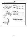
l P Series Module Main Unit
l R Series Module Main Unit
l EXEA Controller
User’s Manual 3
= Installation and Maintenance of Module Main Unit =
1 Installation and Maintenance
2 Programming and Operation
of EXEA Controller
1. Introduction
2. Safety Precautions
3. System Configuration
4. Glossary
5. Reference Number • Specifications
6. Unpacking and Installation
7. Wiring
8. Startup
9. Initial Setting
10. Trial Running
11. Protection and Safety
12. Maintenance • Checking
13. Alarms
14. Troubleshooting
Appendix
3 Installation and Maintenance
of Module Main Unit
of EXEA Controller
15.
16.
17.
18.
Programming
Description of Function
Operation of Robot Module
Remote Control Operation
19.
20.
21.
22.
Reference Number • Specifications
Unpacking
Installation
Maintenance • Checking
M–E099XE0K2–021
Document Number: K20077-01
EC-T
Limited Warranty
NSK Ltd. warrants its products to be free from defects in material and/or workmanship which NSK
Ltd. is notified of in writing within, which comes first, one (1) year of shipment or 2400 total
operation hours. NSK Ltd., at its option, and with transportation charges prepaid by the claimant,
will repair or replace any product which has been proved to the satisfaction of NSK Ltd. to have a
defect in material and/or workmanship.
This warranty is the sole and exclusive remedy available, and under no circumstances shall NSK
Ltd. be liable for any consequential damages, loss of profits and/or personal injury as a result of
claim arising under this limited warranty. NSK Ltd. makes no other warranty express or implied,
and disclaims any warranties for fitness for a particular purpose or merchantability.
Copyright 2000 by NSK Ltd., Tokyo, Japan
All rights reserved.
No part of this publication may be reproduced in any
form or by any means without permission in writing from
NSK Ltd.
NSK Ltd. reserves the right to make changes to any
products herein to improve reliability, function or design
without prior notice and without any obligation.
NSK Ltd. does not assume any liability arising out of the
application or use of any product described herein;
neither does it convey any licence under its present patent
nor the rights of others.
Patents issued and patents pending.
Robot Module System
EC Directives Conformity
NSK Ltd. declares that "Robot Module System" conforms to EC Directive (CE Marking).
However, please note that the following conditions are added for conformity to the EC directive.
¤ EC Declaration of Incorporation
l NSK Ltd. declares that the Robot Module System is a machine component which is to be
incorporated into the machine. ( EC Declaration of Incorporation )
l The Robot Module System must not be operated until it is incorporated to the machine.
l The Robot Module System, as the machine component, conforms with following EC Directives.
à EC Machinery Directive 89/392 as amended 94/368 and 93/44.
à EC Low Voltage Directive 73/23 as amended 93/68.
l The customer has to take appropriate measures to its machine to conform to Electro Magnetic
Compatibility Directive. The Robot Module must not put into service until the machinery into
which it to be incorporated has been declared in conformity with the provisions of EC
Directives.
l Our declaration becomes invalid if technical or operational modifications are introduced without
the consent of Mechatronics Technology Department of NSK Ltd.
¤ Remaining Hazards
(Following notes should be observed for your safety.)
l EXEA controller shall be put into the enclosure conforming to relevant European standard in
terms of fire protection and electrical shock protection. The protection grade of the enclosure
must be IP 54 or better. EXEA controller shall not be exposed to water or oil.
l Just after the power is turned on and off, there will be the hazardous voltage on the parts of
EXEA controller, such as the power input terminal, motor connector and connector for an
external regenerative dump resistor. Put covers on those parts to protect from touching when
operating the machine or doing maintenance work.
Furthermore, provide appropriate protection from disconnecting the motor connector accidentally.
l An isolation transformer must be used to prevent electrical shock. The isolation transformer
must have enough capacity for the Robot Module System power consumption.
l Install noise filter in the primary AC power line as a measure for Electro Magnetic
Compatibility Directive.
l A circuit breaker must be installed to the primary AC power line of Robot Module System.
l Ground earthing must be provided to EXEA controller.
l Wiring inside of EXEA controller is simply internal wirings and the grounding wire is not
distinguished by color as the protective grounding conductive.
l Secure the controller cables and motor cables firmly so that those cables do not break or have
loose contact.
l Surround the machine, to which the Robot Module System is incorporated, with safety fence to
prevent any personnel from entering its moving range.
—i—
¤ Unit Limitation
l Units of Robot Module System which conform to EC Directives are limited to the following
reference number only.
1. EXEA controller
Reference No. : M-EXEA ¨ – ¨ ¨ ¨ ¨ T ¨ ¨
T : Indicates conformity with the Directive
2. Teaching box
Reference No. : M-EXTB 04
l However, all robot module main units are compatible with the EC Directives. If you require to
build the Robot Module System that complies to the EC Directives, the EXEA controller and
the Teaching box must be compatible with the EC Directives.
— ii —
3 Installation and Maintenance of Module Main Unit
“19. Reference Number • Specifications”
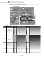
19. Reference Number • Specifications
19.1. Module Main Unit
19.1.1. Reference Number
Reference number example:
XY-HRS 030 - R H 2 00
(1) NSK robot module
(2) Stroke [cm]
(7) Description code
(Example) 030: 300 mm
(6) Ball screw lead [cm]
1 : 10 mm 2: 20 mm
(3) Specification code
– : [standard specification]
C : [clean room specification] Available to R series only
4 : 40 mm
(5) Module type ··· Capacity classification in each series
(cross section area of main unit)
H : Main unit carrying heavy load.
M : Main unit carrying medium load.
S : Main unit carrying light load.
(4) Series
P : [P series]
R : [R series]
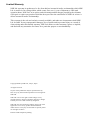
Table 19-1: Description code
(7)
Speed reduction ratio 1/2
Equipped with motor brake
Motor right mount
Motor left mount
Motor back mount
High performance module
00
(7)
Speed reduction ratio 1/2
Equipped with motor brake
Motor right mount
Motor left mount
Motor back mount
High performance module *
32
ü
01
ü
33
ü
ü
02
ü
34
ü
ü
03
ü
ü
35
ü
ü
ü
04
05
ü
ü
ü
36
37
ü
ü
ü
ü
06
ü
ü
38
ü
ü
ü
ü
07
ü
ü
ü
39
ü
ü
ü
ü
08
09
ü
10
ü
11
ü
ü
ü
ü
ü
ü
40
41
ü
42
ü
43
ü
ü
ü
ü
ü
ü
ü
ü
ü
ü
12
13
ü
14
ü
15
ü
ü
ü
ü
ü
ü
44
45
ü
46
ü
47
ü
ü
ü
ü
ü
ü
ü
ü
ü
ü
[Examples]
à Description code [05] : Maximum speed is reduced to 1/2. Motor brake is not
incorporated.
Motor is mounted to right side. (indirect mount)
As the maximum speed is reduced to one half of standard specification,
equivalent ball screw lead in “Motor conversion table” shall be 20 mm if the
ball screw lead number is [4] (40 mm) in (6).
à Description code [00] : The maximum speed is standard. Direct motor mount
main unit and no motor brake is equipped.
* High performance module is equipped with a higher power motor and has higher
transportable moment as shown in Table 19-2 below.
Table 19-2
Motor power [W]
Transportable
moment [Nm]
Rolling
Pitching
Yawing
RM module
RS module
00 ~ 15 normal 32 ~ 47 high performance 00 ~ 15 normal 32 ~ 47 high performance
specifications
specification
specifications
specification
200
400
100
200
70
24
32
120
10
24
120
10
24
— 19-1 —
3 Installation and Maintenance of Module Main Unit
“19. Reference Number • Specifications”
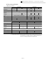
19.1.2. Specifications
u Standard specifications
Table 19-3 : P series
Item
PM module
PH module
212
100
102
200
212
100
100, 200, 300, 400, 500, 600, 700, 800
1200
600
1200
200
Stroke [mm]
Maximum speed [mm/s]
Horizontal transportable
mass [kg]
Vertical transportable
mass [kg]
Transportable moment
[N·m]*1
Repeatability [mm]
Motor power [W]
Ball screw lead [mm]
Ambient temperature
20
40
102
600
80
40
–
8
25
–
Rolling: 19, Pitching: 25, Yawing: 22
Rolling: 113, Pitching: 97, Yawing: 66
±0.02
100
±0.02
200
20
10
10
20
0~40°C (no condensation)
Table 19-4 : R series
Item
Stroke [mm]
Maximum speed [mm/s]
Horizontal transportable
mass [kg]
Vertical transportable
mass [kg]
Transportable moment
[N·m]*1
Repeatability [mm]
Motor power [W]
Ball screw lead [mm]
Ambient temperature
Item
Stroke [mm]
Maximum speed [mm/s]
Horizontal transportable
mass [kg]
Vertical transportable
mass [kg]
Transportable moment
[N·m]*1
Repeatability [mm]
Motor power [W]
Ball screw lead [mm]
Ambient temperature
RS module
104/108
106/110
130, 230, 330, 430, 530, 630
600
204/208
330, 430, 530, 630
1200
138/142
100, 200, 300, 400, 500, 600
600
20
20
–
8
20
Rolling: 24, Pitching: 10, Yawing: 10
Rolling: 32, Pitching: 24, Yawing: 24
±0.01
100
±0.01
200
10
20
10
0~40°C (no condensation)
RM module
RH module
200/204 234/238 134/239
200/204 202/206 102/207
405/409 439/443
405/409 407/411
/208
/242
/243
/208
/210
/211
1200, 1400, 1600,
250, 350, 450, 550, 750, 950
1150, 1350, 1550
300, 400, 500, 600, 800, 1000
1800, 2000
1200, 1080, 840,
1200
600
1200, 1080, 840
1200
600
680, 560
40
–
20
40
80
–
20
Rolling: 70, Pitching: 120, Yawing: 120
±0.01
200
400
20
10 or
equivalent
–
20
40
80
–
20
Rolling: 600, Pitching: 450, Yawing: 400
±0.02
200
400
40
(20 equivalent)
200
±0.01
±0.02
400
20
10 or
equivalent
40
(20 equivalent)
0~40°C (no condensation)
*1 Transportable moment : Maximum moment load for which a module main unit can last out
an estimated life of 10 000 km when it is applied continuously in
either one of rolling, pitching and yawing direction.
— 19-2 —
3 Installation and Maintenance of Module Main Unit
“19. Reference Number • Specifications”
u Clean room specifications
Table 19-5 : R series
Item
Stroke [mm]
Maximum speed [mm/s]
Horizontal transportable
mass [kg]
Vertical transportable
mass [kg]
Transportable moment
[N·m]*1
Repeatability [mm]
Motor power [W]
Ball screw lead [mm]
Ambient temperature
RS module
104/108
204/208
330, 430,
530, 630
1200
106/110
130, 230, 330, 430, 530, 630
600
RM module
200
134
405/409
439/443
250, 350, 450,
1150, 1350, 1550
550, 750, 950
1200
600
1200, 1080, 840
20
40
–
8
–
Rolling: 20, Pitching: 10, Pitching: 10
±0.01
100
20
10
40
–
20
Rolling: 60, Pitching: 120, Pitching: 120
±0.01
200
400
20
10
0~40°C (no condensation)
±0.02
200
400
40 (20 equivalent)
RH module
Item
Stroke [mm]
Maximum speed [mm/s]
Horizontal transportable
mass [kg]
Vertical transportable
mass [kg]
Transportable moment
[N·m]*1
Repeatability [mm]
Motor power [W]
Ball screw lead [mm]
Ambient temperature
200
102
300, 400, 500, 600, 800, 1000
1200
600
80
200
–
40
405/409
407/411
1200, 1400, 1600, 1800, 2000
1200, 1080, 840, 680, 560
80
–
20
Rolling: 550, Pitching: 450, Pitching: 400
±0.01
200
20
±0.02
400
200
10
0~40°C (no condensation)
400
40 (20 equivalent)
*1 Transportable moment : Maximum moment load for which a module main unit can last out
an estimated life of 10 000 km when it is applied continuously in
either one of rolling, pitching and yawing direction.
— 19-3 —
3 Installation and Maintenance of Module Main Unit
“19. Reference Number • Specifications”
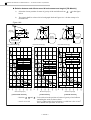
u Transportable mass of single axis moving main unit
l Transportable mass shown in Table 19-6 are applicable for all modules in standard and clean
room specifications when it is used as a moving main unit.
(The specification is valid when the center of gravity of the work is within 50 mm from the
mounting surface of a main unit as indicated in Figure 19-1.)
Table 19-6 : Transportable mass for single axis in moving main unit
H module
transportable mass
stroke [mm]
W [kg]
300
40
400
40
500
40
600
36
800
25
1000
17
M module
transportable mass
stroke [mm]
W [kg]
250
25
350
20
450
16
550
12
750
7
950
3
S module
transportable mass
stroke [mm]
W [kg]
130
3
230
1.4
Figure 19-1: Position of center of gravity of load
Wkg
Work
within 50 mm
Wkg
Work
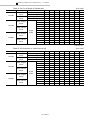
u Transportable mass of multi-axis combination
l Stroke and transportable mass of respective multi-axis combinations is indicated in Table 19-4.
Figure 19-2 : Combination code
Y
— 19-4 —
3 Installation and Maintenance of Module Main Unit
“19. Reference Number • Specifications”
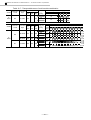
Table 19-7 : Transportable mass of multi-module combination
Series
Combinatio Combination
style
n code
PG
P
series
PD
(wall mount)
PG-HM
PD-MMz
PD-HMz
RG-MS
RG
RG-HM
RD-MS
R
series
RD
RD-HM
RT
RT-MSz
RX-HM
RX
RS-HH
Series
Combination Combination
code
style
PG
P
series
PD
(wall mount)
PG-HM
PD-MMz
PD-HMz
RG-MS
RG
RG-HM
RD-MS
R
series
RD
RD-HM
RT
RT-MSz
RX-HM
RX
RS-HH
Module main unit Acceleratio
n
X
Y
Z
[m/s2]
axis axis axis
4.9
PH PM
–
9.8
4.9
PM –
PM
9.8
4.9
PH –
PM
9.8
4.9
RM RS
–
9.8
4.9
RH RM
–
9.8
4.9
RM RS
–
9.8
4.9
RH RM
–
9.8
4.9
RM –
RS
9.8
3.3
RH RM
–
4.9
3.3
RH RH
–
4.9
Transportable mass [kg]
Y (Z) axis stroke [mm]
100 130 200 230 250 300 330 350 400 430 450
20
19
13.5
10
10
10
9
6
7.5
5.5
4
3
3.6
2.5
1.8
1.2
8
8
5
4
8
5.5
3.6
3
20
15
11
8
18
12
9
6.5
40
40
40
40
40
33
20
20
20
20
20
20
20
20
40
40
40
40
40
40
20
20
20
20
24
19
15
21
16
12
40
40
40
40
Module main unit Acceleratio
n
X
Y
Z
[m/s2]
axis axis axis
4.9
PH PM
–
9.8
4.9
PM
–
PM
9.8
4.9
PH
–
PM
9.8
4.9
RM RS
–
9.8
4.9
RH RM
–
9.8
4.9
RM RS
–
9.8
4.9
RH RM
–
9.8
4.9
RM
–
RS
9.8
3.3
RH RM
–
4.9
3.3
RH RH
–
4.9
Transportable mass [kg]
Y (Z) axis stroke [mm]
550 600 630 700 750 800
5.3
3.6
2.2
2.6
1.3
1
500
7.3
4
2
0.8
3.2
2.5
530
2.9
2.2
6
5
4
3.5
40
28
33
19
24
13
40
40
40
40
40
40
12
9
7
5
3
2
20
20
40
39
— 19-5 —
950 1000
20
20
29
28
20
19
3 Installation and Maintenance of Module Main Unit
“19. Reference Number • Specifications”
Table 19-7 : Transportable mass of multi-module combination
Series
R
series
Combinatio Combination
style
n code
RC
RC-MSz
Module main unit Acceleratio
n
X
Y
Z
[m/s2]
axis axis axis
3.3
4.9
RM
–
RSz
3.3
4.9
Transportable mass [kg]
Z axis stroke [mm] Y axis stroke [mm]
100
250 350 450 550
8
8
8 5.4
130
8
8 5.4 2.4
8
8
7 4.7
230
8
8 4.7 1.7
Module main unit
Combinatio Combination
Series
style
n code
X
axis
Y
axis
RP-MSSz
RM
RS
RP-HMSz
RH
RM
RJ-HMSz
RH
RM
RP
R
series
RJ
Transportable mass [kg]
Acceleratio
Z
axis
Y axis stroke [mm]
n
Z
stroke
2
[m/s
]
axis
130 230 250 330 350 430 450 530 550 630 750 950
[mm]
8
8
4.8
1.8
4.9
130
8 5.8
2.8
9.8
RSz
8
8
4.1
1.1
4.9
230
8 5.1
2.1
9.8
20
20
20
20
20 16
4.9
100,
RSz
200
20
20
20
20
12.6 6.6
9.8
8
8
8
5.4
3.3
130
8
8
5.4
2.4
4.9
RSz
8
8
7.7
4.7
3.3
230
8
8
4.7
1.7
4.9
— 19-6 —
3 Installation and Maintenance of Module Main Unit
“19. Reference Number • Specifications”
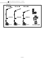
19.1.3. Precautions against Use of Module Main Unit
l Follow the checking procedure in Figure 19-3 to use the module main units properly.
Figure 19-3: Checking procedure [Mass of end effector, position of center of gravity of end
effector, acceleration of module main unit]
When the center of gravity of end effector is within
50 mm from the center of mounting surface
Load shall be within the transportable
mass shown in the Tables 19-3 to 19-5.
PM module: Refer to Figure 19-4.
PH module: Refer to Figure 19-5.
Single
axis
RS module: Refer to Figure 19-6.
RS module, high performance
specification: Refer to Figure 19-7.
Exceeds 50 mm
RM module: Refer to Figure 19-8.
Note (1)
RH module: Refer to Figure 19-9.
RS module: Refer to Figure 19-10.
RM module, clean room specification:
Refer to Figure 19-11.
When the center of gravity of end effector is within 50
mm from the center of mounting surface of slider
Multiaxis
Note (2)
RH module, clean room specification:
Refer to Figure 19-12.
Load shall be within the transportable
mass shown in Table 19-6.
Exceeds 50 mm
Contact your local NSK
Note (1)
à Figures 19-4 to 19-12 show the criteria of moment load for which a main unit can last
out an estimated life of 10 000 km.
à The factors to define the criteria are:
• Mass of end effector (include mass of the work).
• Distance of the center of gravity of end effector from the mounting surface of
slider (moment arm length L that is in normal direction of the mounting surface).
• Acceleration.
• Mounting position of robot
à Graphs in the figures show the relation between the mass of end effector and the
moment arm length L for respective combinations of specific acceleration and position
of center of gravity of the end effector.
à Refer to Figure 19-15 for acceleration set to the controller and positioning time.
Note (2)
à For multi-axis combination, following two factors shall be examined for a module
main unit.
• End effector mass W (load mass) shall be in the specification range stated on
Table 19-6.
• Relation of the position of end effector and the main unit, to which the end
effector is attached, shall be at lower left of a graph.
— 19-7 —
3 Installation and Maintenance of Module Main Unit
“19. Reference Number • Specifications”
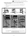
u Relation between end effector mass and moment arm length L [PM Module]
1)
Select the closest position of center of gravity of the end effector from 1 ~ 3 in the figure
below.
2)
The criteria shall be at lower left of each graph. Refer to Figure 19-13 for the concept of
a moment load.
Figure 19-4
1
3
1
Moment
arm length
L
2
2
1
3
1/2
1/2
2
1
1
3
1
1
1/2
1
Module main unit,
horizontal mount
1
1
Module
main unit,
wall mount
Moment arm length
L
1
1
Moment arm length
L
Transportable load mass [kg]
Transportable load mass [kg]
Transportable load mass [kg]
40
40
8
Module main
unit, vertical
mount
Position 1 . Accel. 4.9
35
35
Position 1 . Accel. 9.8
7
Position 3 . Accel. 4.9
Position 2 . Accel. 4.9
30
30
6
25
25
5
Max. 20 kg for main unit of
1.2 m /s maximum speed.
20
Position 1 . Accel. 4.9
Max. 20 kg for main unit of
1.2 m /s maximum speed.
20
4
Position 3 . Accel. 4.9
Position 1 . Accel. 9.8
Position 2 . Accel. 4.9
Position 3 . Accel. 4.9 15
15
Position 1 . Accel. 4.9
Position 2 . Accel. 4.9
Position 3 . Accel. 9.8
Position 3 . Accel. 9.8
10
Position 2 . Accel. 9.8
0
0
200
300
400
Moment arm length [mm]
[Horizontal mount]
500
600
2
Position 2 . Accel. 9.8
5
100
Position 1 . Accel. 9.8
10
5
50
3
Position 3 . Accel. 9.8
1
Position 2 . Accel. 9.8
50
100
200
300
0
400
Moment arm length [mm]
[Wall mount]
500
600 50
100
200
300
400
500
600
Moment arm length [mm]
[Vertical mount]
• Position 1 , 2 and 3 : To be referred as the position of center of gravity of end effector
(including the work) as shown above.
• Accel. 4.9 or 9.8
: Accel. is abbreviation for acceleration. A solid line is for 4.9 m/s2
and a dotted line represents for 9.8 m/s2.
— 19-8 —
3 Installation and Maintenance of Module Main Unit
“19. Reference Number • Specifications”
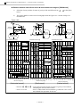
u Relation between end effector mass W and moment arm length L [PH Module]
1)
Select the closest position of center of gravity of the end effector from 1 ~ 3 in the figure
below.
2)
The criteria shall be at lower left of each graph. Refer to Figure 19-13 for the concept of a
moment load.
Figure 19-5
1
3
1
Moment
arm length
L
2
2
1
3
1/2
1
1
3
1
1
1/2
1
Module main unit,
horizontal mount
1
1
Module
main unit,
wall mount
Moment arm length
L
Transportable load mass [kg]
Transportable load mass [kg]
80.0
80.0
1
1
Module main
unit, vertical
mount
Moment arm length
L
Transportable load mass [kg]
25.0
Position 1 . Accel. 4.9
Position 1 and 3 . Accel. 4.9
70.0
22.5
70.0
Position 1 . Accel. 9.8
Position 3 . Accel. 4.9
Position 3 . Accel. 4.9
60.0
Position 2 . Accel. 4.9
20.0
Position 2 . Accel. 4.9
Position 3 . Accel. 9.8
60.0
1/2
2
Position 1 . Accel. 4.9
Position 2 . Accel. 4.9
17.5
50.0
50.0
15.0
Max. 40 kg for main unit of
1.2 m /s maximum speed.
Max. 40 kg for main unit of
1.2 m /s maximum speed.
40.0
40.0
30.0
30.0
12.5
10.0
Position 2 . Accel. 9.8
Position 3 . Accel. 9.8
20.0
Position 3 . Accel. 9.8
7.5
20.0
5.0
10.0
Position 2 . Accel. 9.8
Position 2 . Accel. 9.8
Position 1 . Accel. 9.8
[Horizontal mount]
Moment arm length [mm]
[Wall mount]
Moment arm length [mm]
[Vertical mount]
• Position 1 , 2 and 3 : To be referred as the position of center of gravity of end effector
(including the work) as shown above.
• Accel. 4.9 or 9.8
: Accel. is abbreviation for acceleration. A solid line is for 4.9 m/s2
and a dotted line represents for 9.8 m/s2.
— 19-9 —
1000
900
800
700
600
500
400
300
900
1000
800
700
600
500
400
300
200
50
100
1000
900
800
700
600
500
400
300
200
100
Moment arm length [mm]
200
0.0
0.0
50
0.0
50
Position 1 . Accel. 9.8
2.5
100
10.0
3 Installation and Maintenance of Module Main Unit
“19. Reference Number • Specifications”
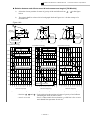
u Relation between end effector mass W and moment arm length L [RS Module]
1)
Select the closest position of center of gravity of the end effector from 1 ~ 3 in the figure
below.
2)
The criteria shall be at lower left of each graph. Refer to Figure 19-13 for the concept of a
moment load.
Figure 19-6
1
3
1
Moment
arm length
L
2
2
1
3
1/2
1/2
2
1
1
3
1
1
1/2
1
Module main unit,
horizontal mount
1
1
Module
main unit,
wall mount
Moment arm length
L
1
1
Moment arm length
L
Transportable load mass [kg]
Transportable load mass [kg]
Transportable load mass [kg]
20
20
8
18
18
7
Position 1 . Accel. 4.9
Position 3 . Accel. 4.9
16
16
6
Position 1 . Accel. 4.9
14
14
Position 3 . Accel. 9.8
5
12
Position 1 . Accel. 9.8
Position 1 . Accel. 9.8
Position 1 . Accel. 9.8
10
Position 3 . Accel. 9.8
Position 3 . Accel. 9.8
Position 3 . Accel. 4.9
12
Module main
unit, vertical
mount
10
Position 2 . Accel. 4.9
Position 2 . Accel. 4.9
4
Position 3 . Accel. 4.9
8
Position 1 . Accel. 4.9
8
Position 2 . Accel. 4.9
6
6
4
4
2
2
3
2
1
[Horizontal mount]
Moment arm length [mm]
[Wall mount]
600.0
500.0
400.0
300.0
200.0
100.0
600.0
500.0
0
400.0
300.0
200.0
100.0
50.0
600.0
500.0
400.0
300.0
200.0
50.0
100.0
Moment arm length [mm]
Position 2 . Accel. 9.8
Position 2 . Accel. 9.8
0
50.0
Position 2 . Accel. 9.8
0
Moment arm length [mm]
[Vertical mount]
• Position 1 , 2 and 3 : To be referred as the position of center of gravity of end effector
(including the work) as shown above.
• Accel. 4.9 or 9.8
: Accel. is abbreviation for acceleration. A solid line is for 4.9 m/s2
and a dotted line represents for 9.8 m/s2.
— 19-10 —
3 Installation and Maintenance of Module Main Unit
“19. Reference Number • Specifications”
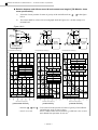
u Relation between end effector W and moment arm length L [RS Module, high
performance specification]
1)
Select the closest position of center of gravity of the end effector from 1 ~ 3 in the figure
below.
2)
The criteria shall be at lower left of each graph. Refer to Figure 19-13 for the concept of a
moment load.
Figure 19-7
1
3
1
Moment
arm length
L
2
2
1
3
1/2
1/2
2
1
1
3
1
1
1/2
1
Module main unit,
horizontal mount
1
1
Module
main unit,
wall mount
Moment arm length
L
1
1
Moment arm length
L
Transportable load mass [kg]
Transportable load mass [kg]
Transportable load mass [kg]
20
20
20
Position 1 . Accel. 4.9
Position 3 . Accel. 4.9
18
Position 3 . Accel. 4.9
18
18
Position 1 . Accel. 4.9
Position 3 . Accel. 9.8
Position 2 . Accel. 4.9
16
Module main
unit, vertical
mount
16
Position 1 . Accel. 9.8
16
Position 3 . Accel. 4.9
14
Position 3 . Accel. 9.8
12
Position 1 . Accel. 9.8
10
Position 2 . Accel. 4.9
Position 1 . Accel. 9.8
14
Position 3 . Accel. 9.8
14
12
12
10
10
8
8
8
6
6
6
4
4
4
Position 2 . Accel. 9.8
2
Position 2 .
Accel. 4.9
Position 1 .
Accel. 4.9
Position 2 . Accel. 9.8
2
2
Position 2 . Accel. 9.8
Moment arm length [mm]
[Horizontal mount]
Moment arm length [mm]
[Wall mount]
600.0
500.0
400.0
300.0
200.0
600.0
500.0
400.0
300.0
200.0
100.0
50.0
600.0
500.0
400.0
300.0
200.0
100.0
50.0
0
100.0
0
50.0
0
Moment arm length [mm]
[Vertical mount]
• Position 1 , 2 and 3 : To be referred as the position of center of gravity of end effector
(including the work) as shown above.
• Accel. 4.9 or 9.8
: Accel. is abbreviation for acceleration. A solid line is for 4.9 m/s2
and a dotted line represents for 9.8 m/s2.
— 19-11 —
3 Installation and Maintenance of Module Main Unit
“19. Reference Number • Specifications”
K Relation between end effector mass W and moment arm length L [RM Module]
1)
Select the closest position of center of gravity of the end effector from 1 ~ 3 in the figure
below.
2)
The criteria shall be at lower left of each graph. Refer to Figure 19-13 for the concept of a
moment load.
Figure 19-8
1
3
1
Moment
arm length
L
2
2
1
3
1/2
1/2
2
1
1
3
1
1
1/2
1
Module main unit,
horizontal mount
1
1
Module
main unit,
wall mount
Moment arm length
L
1
1
Moment arm length
L
Transportable load mass [kg]
Transportable load mass [kg]
Transportable load mass [kg]
40
40
40
Position 1 .
Accel. 4.9
35
Module main
unit, vertical
mount
Position 1 . Accel. 9.8
35
Position 1 .
Accel. 9.8
35
Position 2 . Accel. 9.8
Position 1 . Accel. 4.9
Position 3 . Accel. 4.9
Position 3 . Accel. 4.9
30
30
30
Position 2 . Accel. 4.9
25
25
25
Position 1 . Accel. 9.8
20
20
Position 3 .
Accel. 4.9
15
Position 2 .
Accel. 4.9
15
Position 2 .
Accel. 4.9
10
10
15
10
Position 3 . Accel. 4.9
5
20
Position 1 . Accel. 4.9
5
5
Position 2 . Accel. 9.8
Position 2 . Accel. 9.8
[Horizontal mount]
[Wall mount]
900.0
800.0
700.0
600.0
500.0
400.0
300.0
50.0
100.0
900.0
200.0
Moment arm length [mm]
[Vertical mount]
• Position 1 , 2 and 3 : To be referred as the position of center of gravity of end effector
(including the work) as shown above.
• Accel. 4.9 or 9.8
: Accel. is abbreviation for acceleration. A solid line is for 4.9 m/s2
and a dotted line represents for 9.8 m/s2.
— 19-12 —
1000.0
Moment arm length [mm]
800.0
700.0
600.0
500.0
400.0
300.0
200.0
50.0
0
100.0
900
1000
Position 3 . Accel. 9.8
0
1000.0
Moment arm length [mm]
800
700
600
400
300
200
100
50
500
Position 3 . Accel. 9.8
0
3 Installation and Maintenance of Module Main Unit
“19. Reference Number • Specifications”
K Relation between end effector mass W and moment arm length L [RH Module]
1)
Select the closest position of center of gravity of the end effector from 1 ~ 3 in the figure
below.
2)
The criteria shall be at lower left of each graph. Refer to Figure 19-13 for the concept of a
moment load.
Figure 19-9
1
3
1
Moment
arm length
L
2
2
1
3
1/2
1/2
2
1
1
3
1
1
1/2
1
Module main unit,
horizontal mount
1
1
Module
main unit,
wall mount
Moment arm length
L
1
1
Moment arm length
L
Transportable load mass [kg]
Transportable load mass [kg]
Transportable load mass [kg]
200.0
200.0
40.0
Position 1 . Accel. 4.9
Position 1 . Accel. 9.8
180.0
Position 1 . Accel. 4.9
180.0
Position 2 and 3 . Accel. 4.9
Position 3 . Accel. 9.8
160.0
Position 1 . Accel. 9.8
35.0
160.0
30.0
Position 2 . Accel. 9.8
140.0
140.0
120.0
Position 2 . Accel. 9.8
25.0
120.0
100.0
Module main
unit, vertical
mount
100.0
Max. 80 kg for main unit of
1.2 m /s maximum speed.
80.0
80.0
60.0
60.0
40.0
40.0
20.0
20.0
1 . Accel. 4.9
Position 1 . Accel. 9.8
20.0 Position
Max. 80 kg for main unit of
1.2 m /s maximum speed.
15.0
Position 2 and 3 . Accel. 4.9
Position 3 . Accel. 9.8
10.0
Moment arm length [mm]
[Horizontal mount]
Moment arm length [mm]]
[Wall mount]
Moment arm length [mm]
[Vertical mount]
• Position 1 , 2 and 3 : To be referred as the position of center of gravity of end effector
(including the work) as shown above.
• Accel. 4.9 or 9.8
: Accel. is abbreviation for acceleration. A solid line is for 4.9 m/s2
and a dotted line represents for 9.8 m/s2.
— 19-13 —
1000
900
800
700
600
500
400
300
200
100
50
1000
0.0
900
800
700
600
500
400
300
200
Position 2 and 3 . Accel. 4.9
Position 3 . Accel. 9.8
50
1000
900
800
700
600
500
400
300
200
100
50
0.0
5.0
100
0.0
Position 2 . Accel. 9.8
3 Installation and Maintenance of Module Main Unit
“19. Reference Number • Specifications”
K Relation between end effector mass W and moment arm length L [RS Module, clean
room specification]
1)
Select the closest position of center of gravity of the end effector from 1 ~ 3 in the figure
below.
2)
The criteria shall be at lower left of each graph. Refer to Figure 19-13 for the concept of a
moment load.
Figure 19-10
1
3
1
Moment
arm length
L
2
2
1
3
1/2
1/2
2
1
1
3
1
1
1/2
1
Module main unit,
horizontal mount
1
1
Module
main unit,
wall mount
Moment arm length
L
1
1
Moment arm length
L
Transportable load mass [kg]
Transportable load mass [kg]
Transportable load mass [kg]
20
20
8
18
18
16
7
Position 1 . Accel. 4.9
Position 3 . Accel. 4.9
16
6
Position 1 . Accel. 4.9
14
14
Position 3 . Accel. 9.8
12
5
Position 1 . Accel. 9.8
4
Position 2 . Accel. 4.9
Position 1 . Accel. 9.8
Position 1 . Accel. 9.8
10
Position 3 . Accel. 9.8
Position 3 . Accel. 9.8
Position 3 . Accel. 4.9
12
Module main
unit, vertical
mount
10
Position 2 . Accel. 4.9
Position 3 . Accel. 4.9
8
Position 1 . Accel. 4.9
8
Position 2 . Accel. 4.9
6
3
6
2
1
Position 2 . Accel. 9.8
Position 2 . Accel. 9.8
Position 2 . Accel. 9.8
Moment arm length [mm]
[Horizontal mount]
Moment arm length [mm]
[Wall mount]
600.0
500.0
600.0
500.0
400.0
300.0
200.0
100.0
0
50.0
600.0
500.0
400.0
300.0
200.0
100.0
50.0
0
50.0
0
400.0
2
300.0
2
200.0
4
100.0
4
Moment arm length [mm]
[Vertical mount]
• Position 1 , 2 and 3 : To be referred as the position of center of gravity of end effector
(including the work) as shown above.
• Accel. 4.9 or 9.8
: Accel. is abbreviation for acceleration. A solid line is for 4.9 m/s2
and a dotted line represents for 9.8 m/s2.
— 19-14 —
3 Installation and Maintenance of Module Main Unit
“19. Reference Number • Specifications”
K Relation between end effector mass W and moment arm length L [RM Module, clean
room specification]
1)
Select the closest position of center of gravity of the end effector from 1 ~ 3 in the figure
below.
2)
The criteria hall be at lower left of each graph. Refer to Figure 19-13 for the concept of a
moment load.
Figure 19-11
1
3
1
Moment
arm length
L
2
2
1
3
1/2
1/2
2
1
1
3
1
1
1/2
1
Module main unit,
horizontal mount
1
1
Module
main unit,
wall mount
Moment arm length
L
1
1
Moment arm length
L
Transportable load mass [kg]
Transportable load mass [kg]
Transportable load mass [kg]
40
40
40
Position 3 . Accel. 4.9
Position
1 . Accel.
35
Module main
unit, vertical
mount
Position 3 . Accel. 9.8
35
Position
1 . Accel.
35
Position 1 . Accel. 4.9
Position 2 . Accel. 4.9
Position 2 . Accel. 9.8
30
30
Position 3 . Accel. 4.9
30
Position 2 . Accel. 4.9
25
25
Position 1 . Accel. 9.8
25
Position 3 . Accel. 9.8
20
Position
2 . Accel.
15
10
20
20
15
15
10
10
Position 2 . Accel. 9.8
Position 3 . Accel. 4.9
Position 1 . Accel. 4.9
5
Position 2 . Accel. 9.8
5
Position 1 . Accel. 9.8
Position 3 . Accel. 9.8
0
Moment arm length [mm]
[Horizontal mount]
Moment arm length [mm]
[Wall mount]
Moment arm length [mm]
[Vertical mount]
• Position 1 , 2 and 3 : To be referred as the position of center of gravity of end effector
(including the work) as shown above.
• Accel. 4.9 or 9.8
: Accel. is abbreviation for acceleration. A solid line is for 4.9 m/s2
and a dotted line represents for 9.8 m/s2.
— 19-15 —
1000.0
900.0
800.0
700.0
600.0
500.0
400.0
300.0
200.0
100.0
1000.0
900.0
800.0
700.0
600.0
500.0
400.0
300.0
200.0
50.0
0
100.0
900
1000
800
700
600
500
400
300
200
100
50
0
50.0
5
3 Installation and Maintenance of Module Main Unit
“19. Reference Number • Specifications”
K Relation between end effector mass W and moment arm length L [RH Module, clean
room specification]
1)
Select the closest position of center of gravity of the end effector from 1 ~ 3 in the figure
below.
2)
The criteria shall be at lower left of each graph. Refer to Figure 19-13 for the concept of a
moment load.
Figure 19-12
1
3
1
2
2
1
1/2
2
1
1
3
1
1/2
1
1
Module
main unit,
wall mount
Moment arm length
L
1
1
Moment arm length
L
Transportable load mass [kg]
Transportable load mass [kg]
Transportable load mass [kg]
200.0
200.0
40.0
Position 1 . Accel. 4.9
180.0
Position 2 . Accel. 9.8
25.0
120.0
Max. 80 kg for main unit of
1.2 m /s maximum speed.
100.0
80.0
60.0
60.0
15.0
10.0
Moment arm length [mm]
[Horizontal mount]
Moment arm length [mm]
[Wall mount]
Position 2 . Accel. 9.8
900
0.0
1000
800
200
100
700
Position 2 and 3 . Accel. 4.9
3 . Accel. 9.8
0.0 Position
50
900
1000
800
700
600
500
400
300
200
50
100
0.0
Position 2 and 3 . Accel. 4.9
Position 3 . Accel. 9.8
5.0
600
20.0
500
20.0
400
40.0
300
40.0
Position 1 . Accel. 4.9
Position 1 . Accel. 9.8
900
80.0
20.0
Moment arm length [mm]
[Vertical mount]
• Position 1 , 2 and 3 : To be referred as the position of center of gravity of end effector
(including the work) as shown above.
• Accel. 4.9 or 9.8
: Accel. is abbreviation for acceleration. A solid line is for 4.9 m/s2
and a dotted line represents for 9.8 m/s2.
— 19-16 —
1000
Max. 80 kg for main unit of
1.2 m /s maximum speed.
100.0
500
120.0
400
Position 2 . Accel. 9.8
30.0
300
140.0
35.0
200
140.0
Position 1 . Accel. 9.8
50
160.0
Position 2 and 3 . Accel. 4.9 160.0
Position 3 . Accel. 9.8
100
Position 1 . Accel. 4.9
Position 1 . Accel. 9.8
180.0
Module main
unit, vertical
mount
800
Module main unit,
horizontal mount
1
700
1
600
Moment
arm length
L
3
1/2
3 Installation and Maintenance of Module Main Unit
Specifications”
Figure 19-13: Concept and direction of moment
— 19-17 —
“19. Reference Number •
3 Installation and Maintenance of Module Main Unit
“19. Reference Number •
Specifications”
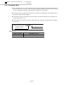
Figure 19-14: Standard operation pattern
l Standard operation pattern defined as shown below may be carried out continuously when the load mass is in the
transportable mass specified in Table 19-6. If an operation that exceeds conditions of the standard operation pattern is
carried out, software thermal of the EXEA controller may function. In such a case, lower the acceleration set in the
controller. (Other measures such as “lower the maximum speed” or “extend stopping time” may be effective. However,
lowering acceleration is the most effective way for the shortest cycle time.)
Acceleration both horizontal and vertical axis: 4.9 m/s2
Speed
horizontally : 1.2 m/s, vertically : 0.6 m/s
Cycle time 3 sec ( includes twice of 0.1 sec stops)
Horizontal stroke : 500 mm
0.66 sec / one way
150mm
Stops for 0.1
Vertical stroke : 150mm
0.37sec / one way
Stops for 0.1
One axis continuous operation is possible if stopping time meets the following conditions.
・Single horizontal main unit : 1.65 sec or more stopping time for a cyclic motion of 500 mm stroke.
・Single vertical main unit : 0.7 sec or more stopping time for a cyclic motion of 150 mm stroke.
Figure 19-15
Stroke - Moving time (exclude settling time)
Speed
0.56 m/s
0.8
4
3.6
0.7
0.6
0.5
3.2
Speed
0.68 m/s
0.4
0.3
2.8
0.2
0.00
0.03
0.06
0.09
0.12
0.15
0.18
0.21
0.24
0.27
0.30
0.33
0.36
0.39
2.4
Speed
0.84 m/s
0
Speed
0.6 m/s
2
Speed
1.08 m/s
Acceleration 3.3m/s2
1.6
Acceleration
1.2
Acceleration 9.8m/s2
0.8
Acceleration 3.3m/s
Speed
1.2 m/s
2
0.4
Acceleration 4.9m/s2
Stroke [mm]
— 19-18 —
2.00
1.90
1.80
0
1.70
1.60
1.50
1.40
1.30
1.20
1.10
1.00
0.90
0.80
0.70
0.60
0.50
0.40
0.30
0.20
0.10
0.00
Acceleration 9.8m/s2
Time [s]
0.1
3 Installation and Maintenance of Module Main Unit
“19. Reference Number •
Specifications”
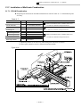
19.2. Controller Cable (Common to P and R Series)
Reference number:
XY-E185 03- 1
Controller cable
Cable length
03 : 3 m
(standard length, available in 1~20 m long upon request)
1 : For a main unit equipped without motor brake
2 : For a main unit equipped with motor brake
Table 19-8
Item
Length
Diameter
Bending radius
Built-in cable
Safety regulation
Specification
1~20 m, available in 1 m step
approximately 14 mm
45 mm or over in inside bending radius (at the fixed position)
For motor and encoder,
(-2: has power cable for motor brake as optional.)
UL Subject 758 (AWM)
Passed VW-1 : Fireproofing test
Figure 19-16
l Use XY-E185¨¨-1 for a main unit without motor brake. They do no have a motor brake
connector. For a main unit with motor brake, use XY-E185¨¨-2.
l We recommend to use a connector box to prevent from pulling the connectors of main unit. If
you do not use the connector box, use a groove of a cable holder to fix the cables.
17
22
Figure 19-17: Cable holder dimensions
11.4
Groove
1.6
16
Caution : The cable holder is fixed to the controller cable. Do not force to move it.
— 19-19 —
3 Installation and Maintenance of Module Main Unit
“19. Reference Number •
Specifications”
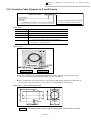
19.3. Cable Support
n Cable support is one of the expendable part of the robot module system. We recommend to replace it after
5 millions cycles to avoid unexpected system shutdown due to a broken cable.
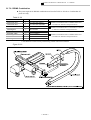
19.3.1. Flexible Tube Type for P Series
l This is a set of a flexible tube and built-in cables. You may add another cables (user cables) and
air-tubes in diameter of ø6 mm or less..
Reference number :
XY-E183 GHM 1 0 0 - 1
Serial number
Cable support
Combination type and odule
GHM: PG combination X axis : PH module
Y axis : PM module
DHM: PD combination X axis : PH/PM module
Z axis : PM module
X axis stroke
0: 100 ~ 400mm
1: 500 ~ 800mm
Number of user cable
0: None 1:0.3mm2 × 6 cables
Number of axes for built-in cables
Table 19-9
Reference
number
XY-
Combination
E183GHM100-1
PG-HM
E183GHM101-1
PG-HM
E183DHM110-1 PD-HM, PD-MM
E183DHM111-1 PD-HM, PD-MM
Internal cable
Number of user
signal cables
Cross section
area available for
additional cables
[mm2]
Motor + Encoder
0
198
Motor + Encoder + power
cable for motor brake
0.3mm2 × 6 cables
160
X axis stroke
100 ~ 400
500 ~ 800
100 ~ 400
500 ~ 800
* Refer to Caution on the next page.
Recommendation of additional cable and air tubes
Robot cable in diameter of 7 ~ 8 mm and it has flexural strength and it is
anti-vibration characteristics.
Urethane tube, 4 ~ 6 mm in diameter (do not use nylon tube)
Cable
Air tube
Flexibility, that is easily bent to approximately R30, is required for the additional
cables and air tubes.
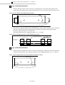
19.3.1.1. Flexible Tube Fixture
l This is to prevent the flexible tube from leaning. Clamp the flexible tube to the fixed side main
unit using the fixture. (common for all combination)
Reference number: XY-P180CC-1
— 19-20 —
3 Installation and Maintenance of Module Main Unit
“19. Reference Number •
Specifications”
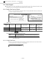
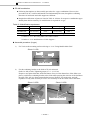
19.3.2. Caterpillar Type for R Series
l Select respectively a “cable support,” which consists of a caterpillar and connector box (boxes),
and “built-in cables.”
Cable support reference number : XY-
E173 P H M S 31 27 - 1
1: Base axis, motor direct mount
2: Base axis, motor indirect mount
E173: For R series
Number of links for secondary axis
Combination style
X axis main unit
Number of links for base axis
Y axis main unit
Z axis main unit
Built-in cable reference number: XY-
E173 010 - 1
E173: For R series
Cable length 010 : 1 m, (numbers in 0.1 m unit)
Figure 19-18
— 19-21 —
1 : main unit with no motor brake
2 : main unit with motor brake
3 Installation and Maintenance of Module Main Unit
“19. Reference Number •
Specifications”
Table 9-10
Combination
RG-MS
RG-HM
RT-MSz
RD-MS
RD-HM
RC-MSz
RX-HM
or
RX-HH
RP-MSSz
RP-HMSz
RJ-HMSz
Stroke [cm]
Y axis
Free
Free
Free
Free
–
–
Free
Free
Free
Free
–
25 ~ 100
X axis
25 ~ 95
* 115 ~ 155 ind.
30 ~ 100
* 120 ~ 200 ind.
25 ~ 95
* 115 ~ 155 ind.
25 ~ 95
* 115 ~ 155 ind.
30 ~ 100
* 120 ~ 200 ind.
25 ~ 55
30 ~ 100
Cable support
Built-in cable
Z axis
–
–
–
–
XY-E173028-2
XY-E173028-2
–
–
–
–
XY-E173028-2
–
Z axis
–
–
–
–
10 ~ 30
10 ~ 30
–
–
–
–
13 ~ 23
–
XY-E173GMS02700-1
XY-E173GMS03900-2
XY-E173GHM02700-1
XY-E173GHM04700-2
XY-E173TM0S3100-1
XY-E173TM0S4300-2
XY-E173DMS01900-1
XY-E173DMS02600-2
XY-E173DHM02000-1
XY-E173DHM03100-2
XY-E173CM0S1500-1
XY-E173XHM03222-1
Y (X) axis
XY-E173020-1
XY-E173028-1
XY-E173020-1
XY-E173028-1
–
–
XY-E173020-1
XY-E173020-1
XY-E173020-1
XY-E173028-1
XY-E173020-1
XY-E173036-1
* 120 ~ 200 ind.
25 ~ 100
–
XY-E173XHM05222-2
XY-E173044-1
–
25 ~ 95
* 115 ~ 155 ind.
30 ~ 100
30 ~ 100
* 120 ~ 200 ind.
* 120 ~ 200 ind.
30 ~ 100
* 120 ~ 200 ind.
13 ~ 43
13 ~ 43
25 ~ 55
75 ~ 95
25 ~ 55
75 ~ 95
25 ~ 55
25 ~ 55
13 ~ 23
13 ~ 23
10 ~ 40
10 ~ 40
10 ~ 40
10 ~ 40
13 ~ 23
13 ~ 23
XY-E173PMSS2716-1
XY-E173PMSS3916-2
XY-E173PHMS2720-1
XY-E173PHMS2728-1
XY-E173PHMS4720-2
XY-E173PHMS4728-2
XY-E173JHMS3217-1
XY-E173JHMS5217-2
XY-E173020-1
XY-E173036-1
XY-E173020-1
XY-E173020-1
XY-E173028-1
XY-E173028-1
XY-E173044-1
XY-E173052-1
XY-E173036-2
XY-E173044-2
XY-E173036-2
XY-E173036-2
XY-E173044-2
XY-E173044-2
XY-E173044-2
XY-E173052-2
Note *: ind. Stands for indirect motor mount.
Caution : 6 cables out of 8 shielded cables for a main unit equipped with motor brake
(XY-E183D¨-1 or XYE173¨¨¨-2) may be shared with the user signal
cables. However, the user signal cables will be in a same rope-lay
conductors with the motor brake excitation cable. Even though a surge
suppresser is installed to the motor brake circuit, noise may cause problems
when the motor brake is on and off. Take the following measures in such a
case.
à Install noise filters to the signal cables.
à Provide a 24 VDC power supply for signal circuit besides the internal
power supply of the EXEA controller.
Fixed side of the cable shield is a round terminal. Connect it to the ground
wiring of user’s equipment through an M3 screw of the connector box.
— 19-22 —
3 Installation and Maintenance of Module Main Unit
“19. Reference Number •
Specifications”
19.4. Combining Bracket
l The bracket is used to combine the main units into a multi-axis combination.
l The bracket for R series uses the locating pins to link itself together the main units. This makes
remounting main units highly accurate.
Reference number :
XY - P175 G H M - 1
Design serial number
P175: for R series,
P185: for P series
Module main unit, secondary axis
Combination type
Module main unit, base axis
Table 19-11
Series
P
R
Applicable combination
PG-HM
PD-HM
PD-MM
RG-MS
RP-MSSz, X-Y axis
RG-HM
RP-HMSz, XY axis
RP-MSSz, YZ axis
RD-MS
RP-HMSz, YZ axis
RD-HM
RX-HM
RC-MSz, X axis
RJ-HMSz, XY axis
RX-HH
RT-MS
RC-MS
RJ-HMSz, YZ axis
Reference number
XY-P185GHM-1*
XY-P185DHM-1
XY-P185DMM-1
Mass [kg]
3.3
0.7
0.5
XY-P175GMS-1*
1.6
XY-P175GHM-1*
3.6
XY-P175DSS-1
0.4
XY-P175DMS-1
0.6
XY-P175DHM-1
1.6
XY-P175XHM-1
1.4
XY-P175XHH-1
XY-P175TMS-1
4.0
1.1
XY-P175CMS-1
0.9
* The bracket for mirror image type combination is available. (XY-P1¨¨5-2)
19.5. Mounting Bracket
l This is to fix the main unit from front side.
Reference number :
XY - P170 H - 1
Design serial number
P170: for R series,
P180: for P series
Module main unit code
Table 19-12
Reference number
XY-P180M-1
XY-P180H-1
XY-P170S-1
XY-P170M-1
XY-P170H-1
XY-P170S-2
Applicable main unit
PM module
PH module
RS module
RM module
RH module
Support slide
— 19-23 —
Mass [kg]
0.4
0.9
0.9
0.4
0.9
0.5
Quantity/axis
2
2
2
2 (3 for 750 mm stroke or over)
2 (3 for 800 mm stroke or over)
3 (5 for 1200 mm stroke or over)
3 Installation and Maintenance of Module Main Unit
“19. Reference Number •
Specifications”
19.6. Connector Box
l This connector box is to stow connectors and to secure the controller cable in operations where
only one main unit is used. You may operate the main unit without the connector box, however,
be sure to clamp the controller cable so that the connectors are not pulled.
l It is not necessary to order the connector box for multi-axis combination. The connector box is
provided as a part of cable support.
l It is not necessary for a main unit of a motor right or left mount main unit. The connectors are
stored in the motor cover.
l This connector box cannot be used for a RS and P series main unit of which motor is mounted
on its back.
Reference number:
XY - P170CB - 1
Design serial number
P170CB: for R series,
P180CB for P series
Table 19-13
Reference number
XY-P180CB-1
XY-P170CB-1
Applicable main unit
Common for PH and PM module
Common for RH and RM module
— 19-24 —
3 Installation and Maintenance of Module Main Unit
“19. Reference Number •
Specifications”
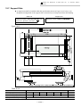
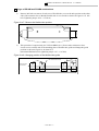
19.7. Support Slide
l A support unit shall be installed within the specifications shown in Figure 19-19 below, even
though the misalignment of the support slide is absorbed by an incorporated linear ball bushing.
Slide unit
Reference number:
Support unit
XY- P177S 030 - 2
Reference number:
XY-P177BGHM-1
Stroke (cm) (Example) 030: 300mm
Figure 19-19
Table 19-14
Item
Stroke [mm]
Maximum speed [mm/s]
Repeatability [mm]
Transportable mass (max.) [kg]
X axis
300 ~ 1000
1200
±0.01
1200
1200
1400
1080
1600
1800
840
680
±0.02
40 (35 for Y axis of 950 mm Y stroke )
— 19-25 —
2000
560
Y axis
250 ~ 950
1200
±0.01
3 Installation and Maintenance of Module Main Unit
“19. Reference Number •
Specifications”
(Blank Page)
— 19-26 —
3 Installation and Maintenance of Module Main Unit
“20. Unpacking”
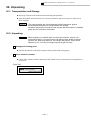
20. Unpacking
20.1. Transportation and Storage
l Do not give shocks to the module main unit during transportation.
l Store the module main unit indoors in a clean environment, and not to expose to wind, rain or
direct sunlight.
Caution
: The robot modules are not provided any special measures against
environmental problems for transportation and storage.
Problems may arise or the service life may be reduced unless it is handled
great care as a precision instrument
20.2. Unpacking
Danger
: When pulling out a module main unit from the container, keep it in its
horizontal position. If you put a main unit without motor brake in vertical
position, the slider may fall by its own weight (back drive), which arises
hazards to you, such as your finger may be caught for injury.
1 Damage and missing parts
l Unpack all containers and check damages on the products and missing parts.
2 Check reference number
l Check if the reference number indicated on the affixed seal to a main unit for correspondence to
your order.
Figure 20-1
Ref No. XY-HRS040-PM200
Ser No. 97N9-002
NSK Ltd. MADE IN JAPAN
— 20-1 —
3 Installation and Maintenance of Module Main Unit
“20. Unpacking”
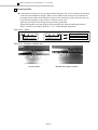
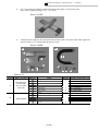
3 Accessory check
l Seals shown in Figure 20-1 are provided with the shipment. The seal is to indicate the positions
of the home and mechanical stopper. When a slider collided with an obstacle, the indication of
original position of home and mechanical stopper will be referred to decide if the main unit can
be operated subsequently to the collision, or requires repair work.
Affix the seals after the first Home return operation is completed.
When affixing the seal, turn off the power and affix the seals on both stroke ends at
where it can be seen clearly. Refer to “17.3.1. Home Return Operation.”
Figure 20-2 : Seals
原
点
MN
メカストッパー
MN
原
Home position
点
メカストッパー
Mechanical stopper
Photo 20-1 : Example of affixed seal
Home position
Mechanical stopper position
— 20-2 —
3 Installation and Maintenance of Module Main Unit
“20. Unpacking”
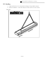
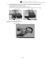
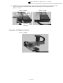
20.3. Handling
1)
Single module main unit : Use main unit body for slinging or fixing to handle or transport.
2)
Multi-axis combination : Fix the robot with ropes or fixture so that it won’t move in transit.
Figure 20-3
— 20-3 —
3 Installation and Maintenance of Module Main Unit
“20. Unpacking”
(Blank Page)
— 20-4 —
3 Installation and Maintenance of Module Main Unit
“21. Installation”
21. Installation
Danger
: Improper mounting of the module main unit may result in mechanical
breakage of the equipment and / or personal injuries.
1) The base axis main unit of a multi-axis combination must be firmly
fixed to the mounting surface by the bolts and the bolt holes as
specified.
2) In case of a multi-axis combination, connect the main units firmly each
other using the specified combining bracket and the bolts.
3) Be fully careful not to break the robot module system by the
mechanical interference, and be most careful not to harm yourself.
Danger
: When carrying a 2 axes combination robot or a combined robot with the end
effector, the sliders of these robots may back-drive and pinch your hands in.
Fix the slider using a rope or etc. not to move while carrying the robot.
Caution
: Do not grab motor cover, connector box or cables when carrying a main
unit.
l Refer to relevant sections in Figure 21-1 for the assembly procedures of your combination.
— 21-1 —
3 Installation and Maintenance of Module Main Unit
“21. Installation”
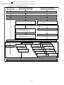
Figure 21-1 : Installation procedure
Single axis
P series 2 axes combination
R series 2 axes combination
21.1. Dimensional Check for Motion Range
21.2. Required Space for Maintenance
21.3. Reversing Main Unit Cable Position
21.8. Shortening of Flexible Tube
21.11. Shortening of Cable Support
It requires to reduce projection of flexible tube.
This procedure requires to reduce projection of a
cable support.
Refer to tables of required modifications for
respective multi-axis combinations.
21.9. Modification of Cable Support
21.12. Reversing Connector Box
This procedure is requires for:
• B, C and D type of PG-HM combination
• B type for PD-¨¨ combination
21.10. Adding Tap Holes to a Module Main Unit
21.13. Reversing L Fixture
• This procedure is required for:
PD-HMz or PD-MMz combination if the Z axis
stroke is 300 mm or over.
21.4. Fixing Module Main Unit
Installation
21.5. Single Axis
Combination of P Series
21.7.1.PG-HM
Combination
Combination of R Series
21.7.4. RG-MS
Combination
21.7.2. PD-MMz
Combination
21.7.5. RG-HM
Combination
21.7.3. PD-HMz
Combination
21.7.9. RX-HH(HM)
Combination
21.7.10. RC-MSz
Combination
21.7.6. RD-MS
Combination
21.7.7. RD-HM
Combination
21.7.8. RT-MSz
Combination
21.7.11. RP-MSSz
Combination
21.7.12. RP-HMSz
Combination
21.7.13. RJ-HMSz
Combination
21.7.14. X axis Motor Indirect Mount Module
21.6. Installation of End Effector
— 21-2 —
3 Installation and Maintenance of Module Main Unit
“21. Installation”
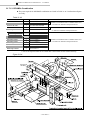
21.1. Dimensional Check for Motion Range
l Specified stroke of a main unit is between home position and just before the end of stroke. There
is approximately 15 mm (10 mm for RS module) allowance to the dead end at both sides. Add
20 mm (15 mm for RS module) or more allowance to the end of specified stroke or the motion
range of robot system for the floor plan so that the robot does not interfere with the ancillaries.
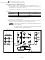
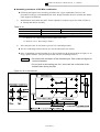
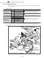
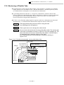
21.2. Required Space for Maintenance
l We recommend to allow an open space for maintenance work. If the space is not wide enough
you may need to dismount a main unit for maintenance work.
à Single axis
: Clear upper side of the main unit and the area shown in
Figure 21.2.
à Multi-axis combination : The area shown in Figure 21-2 is required for motion range
and each axis end.
Figure 21-2: Required space for maintenance
[Unit: mm]
Motor direct mount module
• Inside check
• Wiring check
Motor
200
• Wiring check
Connector
box
500
500
Motor indirect mount module
A person may
get in the area.
500
200
• Check inside
• Wiring check
• Replace timing belt.
Motor
• Wiring check
• Replace timing belt.
500
— 21-3 —
3 Installation and Maintenance of Module Main Unit
“21. Installation”
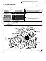
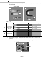
21.3. Reversing Main Unit Cable Position
l Cable position can be changed for motor direct mount, motor back mount and RS module main
units.
l It requires to reverse the cable position of the main units for the following combinations prior to
their installation.
1)
G-HM combination
• B type : PH and PM module
• C type : PH module
• D type : PM module
2)
D-HM and D-MM combination
• A type : Z axis module
• B type : X axis module
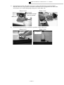
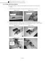
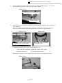
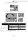
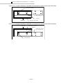
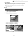
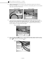
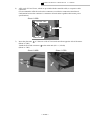
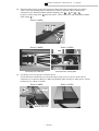
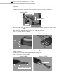
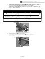
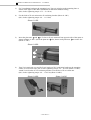
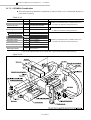
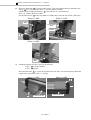
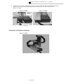
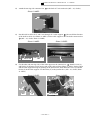
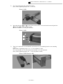
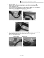
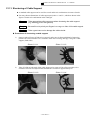
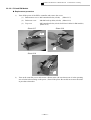
21.3.1. Motor Direct Mount Module
l This section describes the procedure to reverse position of the cables. All procedures hereunder
are common to PH, PM, RH and RM modules, though PH module is shown as an example in the
following photographs.
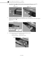
1)
Unfasten the bolts on end surface of main unit. Remove the motor end cover.
Photo 21.3-1
Photo 21.3-2
Motor end cover
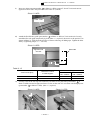
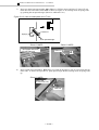
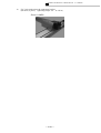
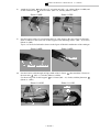
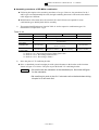
2)
Remove the cables and a blind plug from the motor end cover. (See Photo 21.3-4.)
Photo 21.3-3
Photo 21.3-4
Cable
Blind plug
Blind plug
— 21-4 —
3 Installation and Maintenance of Module Main Unit
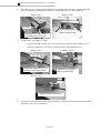
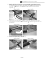
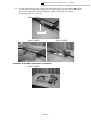
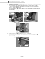
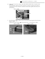
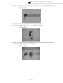
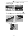
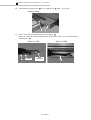
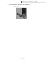
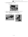
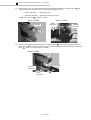
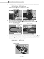
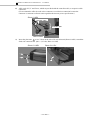
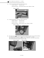
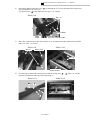
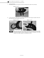
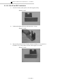
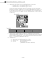
3)
Put bound part of cable with rubber to the groove where the blind plug was inserted before.
Bend the cable into a large radius as possible to minimize force to be applied to the cable outlet
of the motor cover. Put the blind plug to the groove on the other side.
Photo 21.3-5
Blind plug
Photo 21.3-6
Bend cables in a large
radius as possible
Blind plug
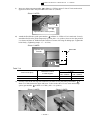
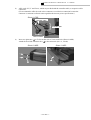
4)
“21. Installation”
Fix the motor end cover. Be careful not to pinch the cables in the cover.
Photo 21.3-7
Photo 21.3-8
Completed
— 21-5 —
3 Installation and Maintenance of Module Main Unit
“21. Installation”
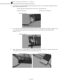
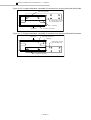
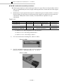
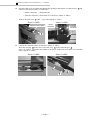
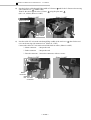
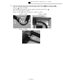
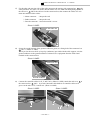
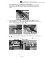
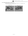
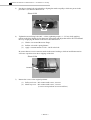
21.3.2. Motor Back Mount Module
l Though PM module is used for the following photos, the procedures are the same for PH
modules.
1)
Remove the motor cover. [M4 × 6. Hexagon socket button head screw. (2 screws)]
Photo 21.3-9
Photo 21.3-10
Motor cover
Cable outlet
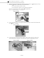
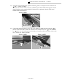
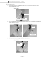
2)
Reverse the cable position. (Photo 21.3-11, -12) Put bound part of cable with rubber to the
opening of the motor cover. (Refer to Photo 21.3-13.) Be careful not to apply excessive bending
force to the cable outlet. Fix the motor cover. (2 screws, M4 × 6)
Photo 21.3-11
Photo 21.3-12
Opening 1
Photo 21.3-13
Opening 1
Bound part
of cable
with rubber
— 21-6 —
3 Installation and Maintenance of Module Main Unit
“21. Installation”
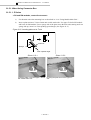
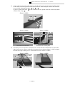
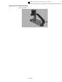
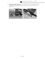
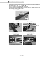
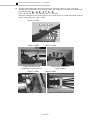
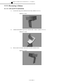
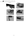
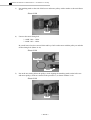
21.3.3. RS Module
1)
Remove the motor end cover. (Unfasten 4 screws, M3 × 6, slotted flat head screw)
Photo 21.3-15
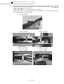
2)
Unfasten the screws (4 screws total, M3 × 6, slotted pan head screw) on the side and end of the
motor cover. (See Photo 21.3-16.)
Photo 21.3-16
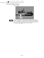
3)
Remove the bottom motor cover in the same manner of procedure (2).
Put the bound part with rubber in the opening at the other end. (See Photo 21.3-17.) Be careful
not to apply excessive bending force to the cable outlet. Fasten the motor cover.
(2 screws, M4 × 6)
Photo 21.3-17
Opening in
end cover
Bound part with
rubber
— 21-7 —
3 Installation and Maintenance of Module Main Unit
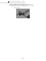
5)
“21. Installation”
Fasten all covers. (See Photo 21.3-18.)
Photo 21.3-18
— 21-8 —
3 Installation and Maintenance of Module Main Unit
“21. Installation”
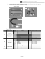
21.4. Fixing Module Main Unit
l The following two ways of mounting method are available. For the both ways, flatness of
mounting base shall be 0.1 mm or less and the surface shall be free of interfering protrusions.
Adjust the flatness of mounting base using shims when there exists clearance between module
surface and mounting base around mounting holes.
1 Fix a module main unit directly to mounting surface with tap holes on its bottom.
l Drill holes through the mounting base and fix a module main unit from its rear side.
(See Figure 21-3.)
l For the R series modules, ø8 H7 holes on its bottom may be used for locating pins to secure
position of a main unit. Refer to Figure 21-4 for specifications of the locating pins.
Figure 21-3
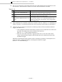
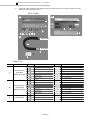
Table 21-1
Bolt size
Screw-in depth
Tightening torque (max.)
PH module
M8
12 ~ 14mm
33.3N·m
PM module
M6
7 ~ 10mm
11.7N·m
RH module
M8
12 ~ 16mm
33.3N·m
RM module
M6
9 ~ 12mm
14.7N·m
RS module
M5
7 ~ 9mm
5.9N·m
2 Use of mounting brackets.
1)
Fix optional mounting brackets to base surface of main unit using bolts provided with the
mounting bracket. (XY-P180¨-1 or XY-P170¨-1)
Refer to Table 21-2 for fastening torque.
2)
Tap on the mounting base and fasten the brackets.
Table 21-2
Bolt dia. × length
Tightening torque
PH module
M8 × 20
33.3N·m
PM module
M6 × 14
11.7N·m
— 21-9 —
RH module
M8 × 20
33.3N·m
RM module
M6 × 20
14.7N·m
RS module
M5 × 16
5.9N·m
3 Installation and Maintenance of Module Main Unit
“21. Installation”
Figure 21-4
— 21-10 —
3 Installation and Maintenance of Module Main Unit
“21. Installation”
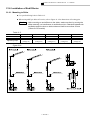
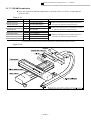
21.5. Installation of Single Axis
l Make sure that all parts and units are ready.
Table 21-3: <P series>
Name
Quantity
Module main unit *2
Controller cable *2
Controller *1
Teaching box
Mounting bracket
Connector box
1
1
1
1
2
1
Reference No.
Comply to CE Marking
(AC 200V)
XY-HRS¨¨¨-PH¨¨¨ or XY-HRS¨¨¨-PM¨¨¨
XY-E185¨¨-1 or -2
M-EXEA¨-¨¨00A00
M-EXEA¨-¨¨00C00
M-EXEA¨-¨¨00T00
M-EXTB03
M-EXTB04
XY-P180H-1 or XY-P180M-1 *3
XY-P180CB-1 (Not applicable to motor back mount module.)
Reference No.
AC200V spec.
Reference No.
AC 100V spec.
Table 21-4 <R series>
Name
Quantity
Module main unit *2
1
Controller cable *2
Controller *1
Teaching box
Mounting bracket
Connector box
1
1
1
2
1
Reference No.
Comply to CE Marking
(AC 200V)
XY-HRS¨¨¨-RH¨¨¨ or XY-HRS¨¨¨-RM¨¨¨
or XY-HRS¨¨¨-RS¨¨¨
XY-E185¨¨-1 or -2
M-EXEA¨-¨¨¨0A00
M-EXEA¨-¨¨¨0C00
M-EXEA¨-¨¨¨0T00
M-EXTB03
M-EXTB04
XY-P170H-1 or XY-P170M-1 or XY-P170S-1 *3
XY-P170CB-1 (Not necessary for motor back mount assembly.)
Reference No.
AC200V spec.
Reference No.
AC 100V spec.
Note: Numbers substituted by ¨ in a reference number varies with stroke, specifications and
module main unit.)
*1. Refer to “5. Reference Number • Specifications” for EXEA controller.
*2. Refer to “19. Reference Number • Specifications” for main unit and controller
cable.
*3. This bracket is not required when the main unit is fixed from its bottom directly.
— 21-11 —
3 Installation and Maintenance of Module Main Unit
“21. Installation”
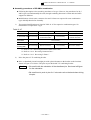
21.5.1. When Using Connector Box
21.5.1.1. P Series
< PH and PM modules, motor direct mount>
1)
Fix the main unit to the mounting base as described in “21.4. Fixing Module Main Unit.”
2)
Insert a plate nut into a T-slot of main unit at cable outlet side. Use upper T-slot for PH module
and lower for PM module. Face a sponge side of the plate nut to the main unit, turning stuck out
sponge side up, insert it to T-slot pushing upward angle. (See Figure 21-5.)
Figure 21-5: Inserting plate nut to T-slot
Plate nut
Sponge
Push upward angle.
Photo 21.5-1
Photo 21.5-2
Plate nut
Plate nut
Insert the plate nut to the upper T-slot of
PH module main unit.
Pushing the plate nut into the upper Tslot.
— 21-12 —
3 Installation and Maintenance of Module Main Unit
3)
“21. Installation”
Fix the connector box frame to the T-slot. (M4, two bolts, tightening torque : 1.5~ 1.8 N·m).
Pass the cables through the U shape opening in the box frame.
Photo 21.5-3
Fixing bolt to plate nut (two bolts)
U shape opening
4)
Affix seals of X, Y, Z and R axes, which are provided with the controller cable, to respective
cable connectors.
(We recommend to affix the seals to the connectors to avoid miss-connection because the
connector is common to all main units regardless their motor power specifications.)
Photo 21.5-4
Photo 21.5-5
Affix seals to connector shells
of controller cable.
Affix seals to all connector shells.
5)
Connect the controller cable to the main unit. (Photo 21.5-6)
à Motor and brake connectors : Push into the end for “click” sound.
à Encoder connectors
: Secure them with two screws.
When putting connectors in the connector box, bend cables in large radius as possible.
Photo 21.5-6
— 21-13 —
3 Installation and Maintenance of Module Main Unit
6)
“21. Installation”
Insert the groove of controller cable holder to an opening in the end cover. Loosely attach the
end cover to the box frame, then loosen the screws of the end cover on the other end.
Photo 21.5-7
Photo 21.5-8
End cover
Insert groove of cable holder in
the opening in the end cover.
7)
Leave the bolts loosely.
Fix the front cover to the box frame.
à Hock lower edge of front cover to a lower groove of the box frame. (Photo 21.5-9)
à Push into upper edge of front cover to box frame. Fasten both end covers.
Photo 21.5-9
Photo 21.5-10
Front cover
Hook lower edge of front cover
to lower groove of box frame.
Push front cover into box
frame by both thumbs.
Photo 21.5-11
Tighten all bolts of end covers.
8)
Connect the controller cable to the EXEA controller. Confirm the affixed seals described in the
procedure 4) for correct connection.
— 21-14 —
3 Installation and Maintenance of Module Main Unit
“21. Installation”
21.5.1.2. R Series
<RH and RM modules, motor direct mount>
1)
Fix a main unit to the mounting base. Refer to “21.4. Fixing Module Main Unit.”
2)
Remove an end cover and top cover. (Photo 21.5-12)
Photo 21.5-12
Top cover
End cover
3)
Insert two plate nuts to the T-slots on a main unit cable side from opposite end of the motor.
Fix the connector box to the main unit by four screws (M3 × 10). Put the cable to U-shape
opening in the box frame. (Photo 21.5-14)
Photo 21.5-13
Photo 21.5-14
Bolt (4 screws)
Plate nut
U shape opening
4)
Affix the seals for “X, Y, Z and R” to the connectors.
(The connectors are common to all modules regardless the motor power specification. Be sure to
affix them to avoid miss-connection.)
Photo 21.5-15
Controller cable
Controller side
Main unit side
— 21-15 —
3 Installation and Maintenance of Module Main Unit
5)
“21. Installation”
Insert the groove of cable holder to the opening in the end cover. Connect the controller cable to
the main unit. (Photo 21.5-16)
à Motor connector and brake power connector : Snap to the end.
à Encoder connector
: Secure it by two setscrews.
Photo 21.5-16
6)
Put connectors in the connector box. Bend the cables in a large radius as possible. Attach the end
cover loosely to the frame body and loosen the screws of the end cover on the other side.
(Photo 21.5-17)
Photo 21.5-17
7)
Then, fix the top cover. Insert the top cover edge to a groove of frame box, then push in the other
side. (Photo 21.5-18) Fasten all screws of the both end covers.
Photo 21.5-18
Photo 21.5-19
— 21-16 —
3 Installation and Maintenance of Module Main Unit
“21. Installation”
21.5.2. When not Using Connector Box
21.5.2.1. All Modules (Excludes RH and RM Motor Indirect Mount Modules)
<Following photos show PM module as an example. However, the procedures are the
same for other modules except RH and RM motor indirect mount modules.>
1)
Fix the main unit to the mounting base referring to “21.4. Fixing Module Main Unit.”
2)
Affix the seals provided with the respective controller cable connectors to indicate X, Y, Z or R
axis. (The connectors are common to all main units regardless the motor power specifications.)
Photo 21.5-20
Main unit cable
3)
Controller cable
Connect the controller cable to the main unit. (Photos 21-21 and 22)
à Motor connector and brake power connector : Snap to the end.
à Encoder connector
: Secure it by two setscrews.
Photo 21.5-21
Photo 21.5-22
Motor indirect mount module
— 21-17 —
3 Installation and Maintenance of Module Main Unit
“21. Installation”
21.5.2.2. RH and RM Motor Indirect Mount Module
<Following photos show RM module as an example. However, the procedures are the
same for RM module.>
1)
Remove the top cover of the motor cover. (Photo 21.5-23)
Photo 21.5-23
2)
Connect the controller cable. Insert the cable holder to the opening in the end cover.
(Photo 21.5-24)
Photo 21.5-24
3)
Fix the top cover.
— 21-18 —
3 Installation and Maintenance of Module Main Unit
“21. Installation”
21.6. Installation of End Effector
21.6.1. Mounting to Slider
l Use specified fixing bolts in Table 21-5.
l When using ø8H7 pin holes of R series, refer to Figure 21-6 for dimensions of locating pins.
Caution
: After mounting an end effector to the slider, make sure that, by moving the
slider manually, no interference in ancillaries exists. Clearance between the
ancillaries and the robot on both stroke end shall be more than 20 mm.
(12mm for RS module)
Table 21-5.
Bolt diameter
Screw-in depth
Tightening toque
PH module
M8
12 ~ 16mm
33.3N·m
{340kgf·cm}
PM module
M6
7 ~ 12mm
11.7N·m
{120kgf·cm}
RH module
M8
12 ~ 16mm
33.3N·m
{340kgf·cm}
Figure 21-6
— 21-19 —
RM module
M6
9 ~ 12mm
14.7N·m
{150kgf·cm}
RS module
M6
6 ~ 8mm
11.7N·m
{120kgf·cm}
3 Installation and Maintenance of Module Main Unit
“21. Installation”
21.6.2. Mounting Effector to End Face of Main Unit
l This way of mounting effector is only applicable to R series.
l Use tap holes on the end face opposite to motor side for mounting. (For both ends for S module.)
l Use the bolts listed in Table 21-6.
l When using ø8H7 pin holes for locating pins, refer to Figure 21-7 for dimensions and positions
of the pin.
l Refer to following sections for maximum transportable mass.
à Single axis operation
: “Table 19-6: Transportable mass for single axis in moving
main unit”
à Multi-axis combination : “Table 19-7: Transportable mass of multi-axis combination”
Danger
: You cannot not use the bolts listed in Table 21-6 to fix a main unit. Refer to
“21.4. Fixing Module Main Unit” to fix the main unit.
Table 21-6
Bolt diameter
Screw-in depth
Tightening torque
RH module
M8
12 ~ 16mm
33.3N·m
{340kgf·cm}
RM module
M6
9 ~ 12mm
14.7N·m
{150kgf·cm}
Figure 21-7
— 21-20 —
RS module
M5
8 ~ 10mm
5.9N·m
{60kgf·cm}
3 Installation and Maintenance of Module Main Unit
“21. Installation”
21.7. Installation of Multi-axis Combination
21.7.1. PG-HM Combination
l Required parts and units for PG-HM combination are listed in Table 21-7. Confirm that all parts
are ready.
Table 21-7
Name
X axis main unit
Quantity
1
Reference number
XY-HRS¨¨¨-PH¨¨¨
Y axis main unit
1
XY-HRS¨¨¨-PM¨0¨
Controller
1
M-EXEA¨-¨¨00¨00
Teaching box
Combining bracket
A and C type
B and D type
Controller cable
Cable support (2)
Mounting bracket
1
M-EXTB0¨
1
XY-P185GHM-1
XY-P185GHM-2
XY-E185¨¨-1
XY-P183GHM10¨-1
XY-P180H-1 (1) (2)
2
1
2
Sections to be referred.
3 Installation and Maintenance of Module Main Unit
(2)
“19. Reference Number and Specifications”
1 Installation and Maintenance of the EXEA Controller
“5. Reference Number and Specifications”
3 Installation and Maintenance of Module Main Unit
“19. Reference Number and Specifications”
(1) Mounting bracket is not necessary when fixing main unit from its bottom.
(2) These parts cannot be used in a motor back mount module.
Figure 21-8
— 21-21 —
3 Installation and Maintenance of Module Main Unit
“21. Installation”
u PG-HM combination
l Following descriptions are the assembly procedure for A type combination. However, the
procedures for B, C and D combinations are fundamentally the same, though the combining
directions of main units and cable support are different.
l Required modifications of parts are listed in Table 21-8 below for respective combination types.
Modify them before assembly. No modification is required for A type.
Table 21-8 Modification requirement
PH main unit
A
Not necessary
PM main unit
Not necessary
Cable support
Not necessary
B
C
D
Reverse the cable outlet. *1
Not necessary
Reverse the cable
Reverse the cable
Not necessary
outlet. *1
outlet. *1
Modification of cable support *2
*1 Refer to “21.3. Reversing Main Unit Cable Position.”
*2 Refer to “21.9. Modification of Cable Support.”
u Assemble procedure (A type)
1)
Fix X axis to the mounting surface referring to “21.4. Fixing Module Main Unit.”
Photo 21-1PG
Slider
Motor
Datum face side
2)
Fix the combining bracket to the slider of X axis main unit.
(Bolt size: M8, 4 bolts. Tightening torque: 27.4 ~ 33.3 N·m)
Prepare a steel plate which has sufficient flatness. Press it to the datum face of the slider (two
places), and fix the combining bracket to the slider while pressing the side face of the bracket to
the plate. This will give better perpendicular between X and Y axes main units, and will
reproduce exactly same accuracy in a case of re-assembly of the two main units in the future.
Photo 21-2PG
Photo 21-3PG
Plate
Datum face (2 places)
Motor side
Combining
bracket
— 21-22 —
3 Installation and Maintenance of Module Main Unit
3)
“21. Installation”
Combine the combining bracket and Y axis main unit.
(M6 bolts: 4 places, tightening torque: 9.8 ~ 11.75 N·m)
Photo 21-4PG
Y axis main unit
4)
Attach the cable support to the main units and connect the cables. Confirm that all parts of the
cable support are ready.
Photo 21-5PG
A
B
5
6
1
C
7
3
2
8
4
9
Table 21-9
Section
A
Name of section
Cable support
B
Flexible tube guide
C
Fixed side connector
Part number
Name of part
Quantity
1
2
3
4
5
Fixed side connector box frame
Front cover
End cover
Flexible tube guide
1
1
1
1
1
6
Square plate nut
Stable side connector box frame
Front cover
Plate nut
2
1
1
1
7
8
9
Plate nut
* These are hexagon socket button head screw.
— 21-23 —
Hexagon socket head
cap screw
M3 × 8 (4 bolts)*
M4 × 6 (2 bolts)
M4 × 6 (2 bolts)
M3 × 8 (4 bolts)*
M4 × 6 (2 bolts)
3 Installation and Maintenance of Module Main Unit
5)
“21. Installation”
Adjust the exposed length of cables at the elbow side to 200 to 220 mm. If additional cables or
air-tubes are required, put them into the flexible tube before this adjustment.
Photo 21-6PG
Elbow side
6)
Fix the fixed side connector box frame to X axis main unit.
Insert the plate nut (part number 4 in Photo 21-5PG) into the upper T-slot at the motor side.
Facing its sponge side to the main unit, turning the stuck out sponge side up, insert it to T slot
pushing upward angle. (See Figure 21-9.)
Figure 21-9: Inserting plate nut to T-slot
Plate nut
Sponge
Push upward angle.
Photo 21-7PG
Photo 21-8PG
Motor side
Upper T-slot
— 21-24 —
3 Installation and Maintenance of Module Main Unit
7)
“21. Installation”
Fix the flexible tube guide to X axis main unit. Insert the square plate nut (part number 6 in
Photo 21-5PG) to the upper T-slot on opposite side of the motor. Facing sponge side to the main
unit, turning the stuck-out sponge side up, push the square plate nut upward angle into T-slot.
(See Figure 21-9.)
Photo 21-9PG
Photo 21-10PG
Opposite side of motor
Upper T-slot
8)
Fix the flexible tube guide temporarily by the bolts. ( M4 × 6, 2 places) Adjust the guide position
using an adding tape to L dimension from the end of motor side of main unit, then tighten the
bolts firmly. (Tightening torque: 1.7 ~ 2.0 N·m) L dimensions are shown in Table 21-10 below.
Photo 21-11PG
Photo 21-12PG
Motor side
L
Flexible tube guide
Table 21-10
X axis stroke [mm]
100 ~ 400
500 ~ 800
9)
Cable support reference number
XY-E183GHM100-1
XY-E183GHM101-1
L [mm]
440
550
Set the fixed side connector box frame to the motor side of main unit so that its side, opposite to
the cable outlet, is flush with the end face of main unit. Pass the main unit cables through U
shape opening on the bottom of the box frame. Tighten the bolts to fix the connector box frame.
(M4 × 6, 2 places, tightening torque: 1.7 ~ 2.0 N·m)
Photo 21-13PG
U shape opening
X axis main
Motor side end
face of X axis
main unit
Fixed side connector box frame
— 21-25 —
3 Installation and Maintenance of Module Main Unit
“21. Installation”
10) Same as X axis main unit, insert the plate nut to fix the fixed side connector box frame (part
number 9 in Photo 21-5PG) to the T-slot 10 on the side of Y axis main unit as shown in Photo
21-14PG.
Facing its sponge side to the main unit, turning the stuck-out sponge side down, insert it into
T-slot pushing downward angle as shown in Figure 21-10.
Figure 21-10
Push downward angle.
Plate nut
Sponge
Photo 21-14PG
Photo 21-15PG
10
Plate nut
Side of Y axis
main unit
12) Set the moving side connector box frame (part number 7 in Photo 21-5PG) to the side of Y
axis main unit so that its elbow side end is flush with the motor side end face of the main unit.
Pass the main unit cables through U shape opening on the bottom of the box. Screw the bolts to
the plate nut and tighten them to fix the connector box. (M4 × 6, 2 places, tightening torque: 1.7
~ 2.0 N·m)
Photo 21-16PG
Photo 21-17PG
Motor side
end face
— 21-26 —
3 Installation and Maintenance of Module Main Unit
“21. Installation”
12) The seals of X, Y, Z and R to identify cables are contained in the controller cable container.
Affix them respectively to the connectors of X and Y axis in the fixed side connector box.
(See Photo 21-18PG.) Affix the seals to connectors of X and Y axis controller cables as well.
(See Photo 21-19PG and Photo 21-20PG.)
Photo 21-18PG
Y axis seal
X axis seal
Photo 21-19PG
Photo 21-20PG
13) Connect the motor connector 11 and sensor connector 12 of the fixed side connector box on Y
axis main unit. Secure the sensor connector firmly with 2 screws. Put the cables in the connector
box. Bend them in a large radius as possible. (Photo 21-21PG)
Loosely attach both covers. (Photo 21-22PG)
End cover of elbow side 13 : M3 × 8 (4 bolts)
End cover 14 : M3 × 8 (4 bolts)
Photo 21-21PG
Photo 21-22PG
11
13
12
14
— 21-27 —
3 Installation and Maintenance of Module Main Unit
“21. Installation”
14) Then attach the front cover of moving side connector box. (part number 8 in Photo 21-5PG)
Hook the edge of front cover to the slot of the connector box frame (in the position 15 in Photo
21-23PG) and push the cover in by both thumbs. (See Photo 21-24PG.)
Photo 21-23PG
Photo 21-24PG
15
Front cover
15) Secure the covers on both ends. (Tightening torque: 0.6 ~ 0.8 N·m)
End cover of elbow side : M3 × 8 (4 bolts)
End cover 16 : M3 × 8 (4 bolts)
Photo 21-25PG
Photo 21-26PG
16
16) Connect X and Y axis cables in the fixed side connector box attached to X axis main unit.
Connect Y axis connectors. Secure the sensor connector 17 with 2 screws. Then connect X axis
connectors as enlarged in Photo 21-28PG. Connection procedures are the same as Y axis.
Photo 21-27PG
Photo 21-28PG
17
Cable holder
— 21-28 —
3 Installation and Maintenance of Module Main Unit
“21. Installation”
17) Insert the cable holders of X and Y axis controller cables to the opening in the end cover with
blind plug. (See Photo 21-29PG.) Insert the Y axis cable holder 18 to the opening first, then X
axis cable holder 19 next. (See Photo 21-30PG for the cable holder.) Then screw down the end
cover. (M3 × 8 bolts, 4 places). Leave the bolts loose. Do same for the end cover on cable
support side 20 .
Photo 21-29PG
Photo 21-30PG
20
Idle holder
19
End cover
18
18) Attach the front cover (part number 2 in Photo 21-5PG) to the connector box frame. Hook
edge of front cover to the slot of box frame (in position 21 ), and push the upper side of the cover
by both thumbs.
Photo 21-31PG
Photo 21-32PG
21
Front cover
19) Tighten the bolts of the covers on both ends.
(8 bolts in total, tightening torque: 0.6 ~ 0.8 N·m)
Photo 21-33PG
Photo 21-34PG
20
End cover
— 21-29 —
3 Installation and Maintenance of Module Main Unit
“21. Installation”
Completion of PG-HM Combination
Photo 21-35PG
20) Move X axis manually to both stroke ends. Check for twist of the flexible tube and interference
with ancillaries. If the flexible tube is twisted during the motion, take measures listed in Table
21-11 for the adjustment.
Table 21-11
No
Cause
1 Flexible tube is inclined.
2
3
4
Measures
Adjust position of the moving side connector box.
Make adjustment by twisting the flexible tube on both ends.
Due to core set of flexible tube.
(Flexible tube can be rotated at tube connectors on both ends.)
The cables are twisted in flexible Disassemble fixed side connector box. Straighten the flexible tube
tube.
to remove twist of the cables.
Shortening the flexible cable is effective when X axis stroke is 500
to 800 mm stroke. (Refer to “21.8. Shortening Flexible Tube.”)
Affected by additional cables.
Addition of a metal fixture (XY-P180CC-1) for fixing flexible
tube is effective as well.
21) After installation of the controller (refer to “6.3. Installation of EXEA Controller”), connect the
controller cables to the controller. Check for affixed seal of each part described in the procedure
12).
22) Affix seals provided with a main unit to indicate the Home and mechanical stopper position.
Firstly, after completion of Home return motion (refer to “17.3.1. Home Return Operation.”),
turn off the power and affix the seal onto a side of a main unit to indicate Home position. Then
move the slider manually to the other end of stroke, keeping turn power off, until slider contacts
the mechanical stopper, then affix another seal to indicate position of the mechanical stopper.
<See Photo 20-1.>
Indication of the position of mechanical stopper will be referred in the future whether a main
unit can be used subsequently if it collided to obstacles including the mechanical stopper.
(Refer to “14. Troubleshooting.”)
— 21-30 —
3 Installation and Maintenance of Module Main Unit
“21. Installation”
21.7.2. Installation of PD-MMz Combination (Exclusive to Wall Mount Type)
l Confirm that all parts and units listed in Table 21-12 are ready.
Table 21-12
Name
Quantity
1
X axis main unit
Reference number
XY-HRS¨¨¨-PM¨¨¨
Z axis main unit
1
XY-HRS¨¨¨-PM102
Controller
1
M-EXEA¨-¨¨00¨00
Teaching box
Combining bracket
X axis controller cable
Z axis controller cable
Cable support
Mounting bracket
1
1
1
1
1
2
M-EXTB0¨
XY-P185DMM-1
XY-E185¨¨-1
XY-E185¨¨-2
XY-P183DHM11¨-1 (1)
XY-P180M-1 (2) (3)
Sections to be referred.
3 Installation and Maintenance of Module Main Unit
(3)
“19. Reference Number and Specifications”
1 Installation and Maintenance of the EXEA Controller
“5. Reference Number and Specifications”
3 Installation and Maintenance of Module Main Unit
“19. Reference Number and Specifications”
(1)
6 signal cables are available for user cables. Hoever, there might be some noise
problems. Refer to “19.3. Cable Support.”
(2)
This is not necessary when fixing X axis from its bottom.
(3)
Motor back mount module cannot be used as a Z axis main unit.
(4)
This bracket cannot be used for a motor back mount module.
Figure 21-11
— 21-31 —
3 Installation and Maintenance of Module Main Unit
“21. Installation”
Figure 21-12: A type combination: Assemble of connector box (moving side) and fixture plate
Use these tap holes.
Fixture plate, m oving
side connector box
Opening
Cable inlet
Connector box frame
Figure 21-13: B type combination: Assembly of connector box (moving side) and fixture plate
Cable inlet
Connector box fram e
Opening
Fixture plate, m oving
side connector box
Use these tap
— 21-32 —
3 Installation and Maintenance of Module Main Unit
“21. Installation”
u PD-MMz combination
l This section describes the assembly procedure of A type combination. For B type combination,
though combining directions of main units and cable support are different from A type,
fundamental procedures are the same.
l Modifications required for parts of respective combinations are listed in Table 21-13. Modify
them before assembly.
Table 21-13
X axis main unit
Z axis main unit
Cable support
A
Not necessary
Reverse cable position *1
Not necessary
B
Reverse cable position *1
Not necessary
Modification of cable support *2
*1. Refer to “21.3. Reversing Main Unit Cable Position”
*2. Refer to “Modification of Cable Support.”
u Assembly procedure (A type)
1)
Fix X axis main unit (PM module) to the mounting base.
Photo 21-1PD
X axis main unit
2)
Turn over Z axis main unit. Fix the combining bracket to ite mounting surface.
(M6 bolts: 4 places, tightening torque: 9.8 ~ 11.75 N·m)
Fix the combining bracket to the slider of X axis main unit.
(M6 bolts: 4 places, tightening torque: 9.8 ~ 11.75 N·m)
Photo 21-2PD
Photo 21-3PD
Z axis main unit
Combining bracket
— 21-33 —
3 Installation and Maintenance of Module Main Unit
3)
“21. Installation”
Attach the cable support to the main unit and wire the cables. Check if all parts listed in Table
21-14 are ready. (Photo 21-4PD)
Photo 21-4PD
B
A
7
1
8
4
6
C
5
2
3
10
9
11
Table 21-14
Section
Name of section
A
Cable support
B
Flexible tube guide
C
Fixture plate, moving
side connector box
Part number
1
2
3
4
5
6
7
8
9
10
11
Name of part
Quantity
Connector box frame, fixed side
End cover
Plate nut
Front cover
Connector box frame, moving side
Front cover
Flexible tube guide
Plate nut
Spacer
Fixture plate, moving side connector
box
Plate nut
1
1
1
1
1
1
1
2
1
Hexagon socket head
cap screw
M3 × 8 (4 bolts) *
M4 × 6 (2 bolts) *
M4 × 12 (2 bolts)
1
M4 × 6 (2 bolts)
2
M4 × 12 (4 bolts)
* These are hexagon socket button head screws.
4)
Unfasten bolts (4 bolts, M3x8) on the end cover of moving side connector box frame and remove
it. (The cover has an opening for additional cables.)
Photo 21-5PD
Photo 21-6PD
End cover
Connector box frame,
moving side
— 21-34 —
3 Installation and Maintenance of Module Main Unit
5)
“21. Installation”
Assemble the fixture plate (part number 10 in Photo 21-4PD) and moving side connector box
frame.
à M4 × 6, 2 places, tightening torque: 1.7 ~ 2.0 N·m
à Use holes shown in Photo 21-7PD and 21-8PD.
Photo 21-7PD
Photo 21-8PD
M4 tap hole
Holes fix to
fixture plate
10
10 magnified
Photo 21-9PD
M4 × 6
10
5
9
6)
Adjust exposed length (L in Photo 21-10PD) of cables from the moving side connector box to
200 to 220 mm using an adding tape as shown in Photo 21-10PD.
Photo 21-10PD
L
— 21-35 —
3 Installation and Maintenance of Module Main Unit
7)
“21. Installation”
Insert two plate nuts (part number 11 in Photo 21-4PD) to upper and lower T-slots of Z axis
main unit at its cable side. Insert them as shown in Figure 21-14, turning stuck out sponge side
up, pushing the nut upward angle. (Photo 21-11PD and 21-12PD)
Figure 21-14: How to insert plate nut to T-slot
Plate nut
Sponge
Push upward angle.
Photo 21-11PD
Photo 21-12PD
T-slot (upper and lower)
of Z axis main unit
8)
Plate nut 11
12
Insert a plate nut (part number 3 in Photo 21-4PD) to the upper T-slot of X axis main unit at
motor side. As shown in Figure 21-14, push upward angle the nut, turning stuck out sponge side
up.
Photo 21-13PD
Motor side
(X axis main unit)
— 21-36 —
3 Installation and Maintenance of Module Main Unit
9)
“21. Installation”
Insert two plate nuts (part number 8 in Photo 21-4PD) to upper T-slot of X axis main unit at
opposite to motor side. This procedure is the same as 7) and 8).
Photo 21-14PD
Lower T-slot
10) Attach the flexible tube guide (part number 7 in Photo 21-4PD) to X axis main unit. Loosely
attach the flex tube guide temporarily by bolts (M4 × 12, 4 places), then set it to the position L as
shown in Photo 21-15PD from the end face of motor side using an adding tape. Tighten the bolts
firmly. (Tightening torque: 1.7 ~ 2.0 N·m)
Photo 21-15PD
Motor side
Opposite side
of motor
7
L
Table 21-15
X axis stroke [mm]
Reference number
of cable support
100 ~ 400
500 ~ 800
XY-E183DHM110-1
XY-E183DHM111-1
L [mm]
Z axis stroke
Z axis stroke
100 ~ 300mm
400 ~ 600mm
650
600
1050
1050
11) Loosely screw in the moving side connector box frame to two plate nuts (part number 11 in
Photo 21-4PD) inserted to upper and lower T-slots on the side of Z axis main unit through spacer
(part number 9 in Photo 21-4PD). (M4 × 12, 4 places)
Photo 21-16PD
Photo 21-17PD
9
— 21-37 —
3 Installation and Maintenance of Module Main Unit
“21. Installation”
12) Position of moving side connector box (distance between its end cover 13 and end face of Z axis
main unit 14 in Photo 21-18PD) must be set as below.
à Z axis stroke 300 mm or under : 124 mm
à Z axis stroke 400 ~ 600 mm
: 0 (zero) (Flush with each other.)
Pass Z axis cables through U shape opening 16 , then tighten bolts.
(M14 × 12, tightening torque 1.7 ~ 2.0 N·m)
Photo 21-18PD
15
14
16
13
Cable
13) Loosely attach the end cover to moving side connector box frame. Loosen bolts of the other end
cover 13 . (M3 × 8, 4 places)
Photo 21-19PD
End cover
13
14) Connect the cables of main unit and cable support. There are three connectors, motor power,
sensor and brake power connectors. Secure the sensor connector by tightening two screws.
Photo 21-20PD
Photo 21-21PD
— 21-38 —
3 Installation and Maintenance of Module Main Unit
“21. Installation”
15) Apply the edge of front cover to the slot of moving side connector box and push the front cover
in.
Photo 21-22PD
Photo 21-23PD
6
16) Fix the both end covers to the connector box. (M3 × 8, tightening torque: 0.6 ~ 0.8 N·m)
Photo 21-24PD
17) Flush the right end surface of the connector box (Part number 1 in Photo 21-4PD) with the end
face of X axis main unit (motor side). Tighten the bolts to fix the connector box to the plate nut
(part number 3 ), which are inserted to T slot in process 8).
(2 places, M4 × 6, tightening torque: 1.7 ~ 2.0 N·m)
Pass the cables of X axis through U shape opening beforehand.
Photo 21-25PD
M4 × 6
X axis end face, motor side
— 21-39 —
3 Installation and Maintenance of Module Main Unit
“21. Installation”
18) Affix the seals provided with the controller cable to identify the connectors for reference in
multi-axis combination.
Seals for X, Y, Z and R axes are provided. Affix them to corresponding cables. For the controller
cable, affix seals both for X and Z axes.
Photo 21-26PD
Photo 21-27PD
Affix the seals.
Affix the seals.
19) Connect X and Z axes connectors of the cable support and controller cable at the fixed side
connector box. The round terminal of earth wiring (green) of cable support must be connected
to M3 tap hole adjacent to M4 bolts. (Tightening torque: 1.6 ~ 1.8 N·m) This fixed round
ground terminal must be connected to the ground wiring of user’s equipment when the user
cable (6 cores) are to be added to the cable support.
Photo 21-28PD
M3 tap hole
M4 × 6
20) Insert cable holders (part number 18 , 19 in Photo 21-4PD) of controller cable to the slot of end
cover (part number 2 in Photo 21-4PD) , to where an idle holder is previously inserted. Insert Z
axis cable holder 18 first, then X axis cable holder 19 .
Photo 21-29PD
Idle holder
19
End cover
18
— 21-40 —
3 Installation and Maintenance of Module Main Unit
“21. Installation”
21) Loosely attach both end covers. (Photo 21-30PD) Fit the front cover (part number 4 in Photo
21-31PD) into the connector box frame. Hook its edge on lower grooves of the box frame and
push it in by both thumbs as shown in Photo 21-32PD. Fix both end covers firmly.
(Tightening torque: 0.6 ~ 0.8 N·m)
Photo 21-30PD
End cover
Photo 21-31PD
Photo 21-32PD
Installation of D-HM combination is completed.
Photo 21-33PD
— 21-41 —
3 Installation and Maintenance of Module Main Unit
“21. Installation”
22) Move X axis manually in full stroke and check twist of the flexible tube and interference with
the ancillaries. Take measures in Table 21-16 below if the flexible tube is twisted.
Table 21-16
No
Cause
1
Due to core set of flexible tube.
2
Cables are twisted in the flexible
tube.
3
Affected by additional cables or air
tube.
Measures
Make adjustment by twisting flexible tube. (Flexible tube can
be rotated at tube connector.) Adjust at both ends.
Disassemble the fixed side connector box. Straighten the
flexible tube to remove twist of the cables.
Shortening the flexible cable is effective when X axis stroke is
500 to 700 mm. (Refer to “21.8. Shortening Flexible Tube.”)
Addition of metal fixture (XY-P180CC-1) for fixing flexible
tube is effective also.
23) After installation of a controller, connect the controller cable to it. (Refer to “6.3. Installation of
EXEA Controller.”) Confirm the affixed seals to the connectors in procedure 18) hereinabove.
24) Affix the seals to X and Z axis main units to indicate positions of Home and the mechanical
stopper. (See Photo 21-1.)
à After completion of Home return motion, turn the power off and affix one of the seals
provided with module main unit to indicate Home position.
(Refer to “17.3.1. Home Return Operation.”)
à Then move the slider manually to opposite stroke end, at where the slider makes
contact with mechanical stopper, and affix the other seal to indicate location of the
mechanical stopper.
Indication of mechanical stopper position will be referred for possibility of subsequent use of
main unit when it collided to obstacles, including the mechanical stopper.
(Refer to “14. Troubleshooting.”)
— 21-42 —
3 Installation and Maintenance of Module Main Unit
“21. Installation”
21.7.3. PD-HM Combination (Exclusive for Wall Mount)
l Table 21-17 shows required parts and units for the combination. Check if all parts are ready.
Table 21-17
Name
Quantity
Reference number
1
XY-HRS¨¨¨-PH¨¨¨
Z axis main unit
1
XY-HRS¨¨¨-PM102
(3)
Controller
1
M-EXEA¨-¨¨00¨00
Teaching box
Combining bracket
X axis controller cable
Z axis controller cable
Cable support
Mounting bracket
1
1
1
1
1
2
M-EXTB0¨
XY-P185DHM-1
XY-E185¨¨-1
XY-E185¨¨-2
XY-P183DHM11¨-1 (1)
XY-P180H-1 (2) (3)
X axis main unit
(1)
(2)
(3)
(4)
Sections to be referred.
3 Installation and Maintenance of Module Main Unit
“19. Reference Number and Specifications”
1 Installation and Maintenance of the EXEA Controller
“5. Reference Number and Specifications”
3 Installation and Maintenance of Module Main Unit
“19. Reference Number and Specifications”
6 signal cables are available for user cables. However, there might be some noise
problems. Refer to “19.3. Cable Support.”
This is not necessary when fixing X axis from its bottom.
Motor back mount module cannot be used as a Z axis main unit.
This bracket cannot be used for a motor back mount module.
Figure 21-15
— 21-43 —
3 Installation and Maintenance of Module Main Unit
“21. Installation”
Figure 21-16: A type combination: Assemble of connector box (moving side) and fixture plate
Use these tap holes.
Fixture plate, m oving
side connector box
Opening
Cable inlet
Connector box frame
Figure 21-17: B type combination: Assembly of connector box (moving side) and fixture plate
Cable inlet
Connector box fram e
Opening
Fixture plate, m oving
side connector box
Use these tap holes.
— 21-44 —
3 Installation and Maintenance of Module Main Unit
“21. Installation”
u PD-HMz combination
l Description hereafter are assemble procedure of A type combination. For B type, though the
orientation of main units and cable support are diferent from A type, fundamental procedures are
the same.
l Table 21-18 below shows modification requirements of main unit prior to assembly for
respective combination types
Table 21-18
A
Not necessary
Reverse cable position. *1
Not necessary
X axis main unit
Z axis main unit
Cable support
B
Reverse cable position. *1
Not necessary
Modification of cable support *2
*1. Refer to “21.3. Reversing Main Unit Cable Position”
*2. Refer to “Modification of Cable Support.”
u Assembly Process (A type)
1)
Fix X axis main unit (PH module) to the mounting base.
Photo 21-34PD
X axis main unit
2)
Turn over Z axis main unit (PM module) and fix the combining bracket to its mounting surface.
(M6 bolts: 4 places, tightening torque: 100 ~ 120 kgf·cm)
then secure the combing bracket firmly to the mounting face of slider of X axis main unit.
(M8 bolts: 4 places, tightening torque: 280 ~ 340 kgf·cm)
Photo 21-35PD
Photo 21-36PD
Z axis main unit
Combining bracket
— 21-45 —
3 Installation and Maintenance of Module Main Unit
3)
“21. Installation”
Attach the cable support to the main units. Be sure that all parts of the cable supports are ready.
Photo 21-37PD
B
A
7
1
8
4
6
C
5
2
3
10
9
11
Table 21-19
Section
Name of section
A
Cable support
B
Flexible tube guide
C
Fixture plate, moving
side connector box
Part number
1
2
3
4
5
6
7
8
9
10
11
4)
Name of part
Quantity
Connector box frame, fixed side
End cover
Plate nut
Front cover
Connector box frame, moving side
Front cover
Flexible tube guide
Plate nut
Spacer
Fixture plate, moving side connector
box
Plate nut
1
1
1
1
1
1
1
2
1
Hexagon socket head
cap screw
M3 × 8 (4 bolts) *
M4 × 6 (2 bolts) *
M4 × 12 (2 bolts)
1
M4 × 6 (2 bolts)
2
M4 × 12 (4 bolts)
Unfasten bolts (4 places, M3 × 8) of the end cover of the moving side connctor box frame and
disassemble it. (this cover has opening for additional cables.)
Photo 21-38PD
Photo 21-39PD
End cover
Moving side connector
box frame.
— 21-46 —
3 Installation and Maintenance of Module Main Unit
5)
“21. Installation”
Assemble a fixture plate (part number 10 ) and moving side connector box.
à M4 × 6, 2 places, fastening torque: 1.7 ~ 2.0 N·m
à Use holes shown in Photo 21-40PD and 21-41PD.
Photo 21-40PD
Photo 21-41PD
M4 tap hole
Holes fix to
fixture plate
10
10 magnified
Photo 21-42PD
M4 × 6
10
5
9
6)
Adjust exposed length (L in Photo 21-43PD) of cables from the moving side connector box to
200 to 220 mm using an adding tape as shown in Photo 21-43PD.
Photo 21-43PD
L
— 21-47 —
3 Installation and Maintenance of Module Main Unit
7)
“21. Installation”
Insert two plate nuts (part number 11 in Photo 21-37PD) to upper and lower T-slots of Z axis
main unit at its cable side. Insert them as shown in Figure 21-18, turning stuck out sponge side
up, pushing the nut upward angle. (Photo 21-44PD and 7-61)
Figure 21-18: How to insert plate nut to T-slot
Plate nut
Sponge
Push upward angle.
Photo 21-44PD
Photo 21-45PD
T-slot (upper and lower)
of Z axis main unit
8)
Plate nut 11
12
Insert a plate nut (part number 3 in Photo 21-37PD) to the upper T-slot of X axis main unit on
motor side. As shown in Figure 21-18, push upward angle the nut, turning stuck out sponge side
up.
Photo 21-46PD
Motor side
(X axis main unit)
Plate nut
— 21-48 —
3 Installation and Maintenance of Module Main Unit
9)
“21. Installation”
Insert two plate nuts (part number 8 in Photo 21-37PD) to upper T-slot of X axis main unit at
opposite to motor side. This procedure is the same as 7) and 8).
Photo 21-47PD
Plate nut 8
Side 12
Opposite side to motor (X axis)
10) Attach the flexible tube guide (part number 7 in Photo 21-37PD) to X axis main unit. Loosely
attach the flexible tube guide temporarily by bolts (M4 × 12, 4 places), then set it to the position
L as shown in Photo 21-48PD from the end face of motor side using an adding tape. Tighten the
bolts firmly. (Tightening torque: 1.7 ~ 2.0 N·m)
Photo 21-48PD
Motor side
Opposite side
of motor
7
L
Table 7-14
X axis stroke [mm]
Reference number
of cable support
100 ~ 400
500 ~ 800
XY-E183DHM110-1
XY-E183DHM111-1
L [mm]
Z axis stroke
Z axis stroke
100 ~ 300mm
400 ~ 600mm
650
600
1100
1100
11) Loosely screw in the moving side connector box frame to two plate nuts (part number 11 in
Photo 21-37PD) inserted to upper and lower T-slots on the side of Z axis main unit through
spacer (part number 9 in Photo 21-37PD). (M4 × 12, 4 places)
Photo 21-49PD
Photo 21-50PD
9
— 21-49 —
3 Installation and Maintenance of Module Main Unit
“21. Installation”
12) Position of moving side connector box (distance between its end cover 13 and end face of Z axis
main unit 14 in Photo 21-51PD) must be set as shown below.
à Z axis stroke 300 mm or under: 124 mm
à Z axis stroke 400 ~ 600 mm : 0 (zero) (Flush with each other.)
Pass Z axis cables through U shape opening 16 , then tighten bolts.
(M14 × 12, tightening torque 1.7 ~ 2.0 N·m)
Photo 21-51PD
15
14
16
13
Cable
13) Loosely attach the end cover to moving side connector box frame. Loosen bolts of the other end
cover 13 . (M3 × 8, 4 places)
Photo 21-52PD
End cover
13
14) Connect the cables of main unit and cable support. There are three connectors, motor power,
sensor and brake power connectors. Secure the sensor connector by tightening two screws.
Photo 21-53PD
Photo 21-54PD
— 21-50 —
3 Installation and Maintenance of Module Main Unit
“21. Installation”
15) Hook the edge of the front cover 6 to lower groove of moving side connector box frame and
push it in by both thumbs.
Photo 21-55PD
Photo 21-56PD
6
16) Secure the end covers of moving side connector box by bolts.
(Bolt size: M3 × 8, tightening torque: 0.6 ~ 0.8 N·m )
Photo 21-57PD
17) Fix the fixed side connector box frame (part number 1 in Photo 21-37PD) to X axis main unit
using the plate nut ((part number 3 in Photo 21-37PD) inserted to T-slot in the procedure 8)
hereinabove.
(Bolt size: M4 × 6, 2 places, tightening torque: 1.7 ~ 2.0 N·m)
à Pass the cables of X axis through U shape opening of the connector box.
à Flush the right side face of connector box with the end face of the main unit motor
side.
Photo 21-58PD
M4 × 6
Motor side end face
of X axis main unit
— 21-51 —
3 Installation and Maintenance of Module Main Unit
“21. Installation”
18) Affix the seals provided with the controller cable to identify the connectors for reference in
multi-axis combination.
Seals for X, Y, Z and R axes are provided. Affix them to corresponding cables. For the controller
cable, affix seals both for X and Z axes.
Photo 21-59PD
Photo 21-60PD
Affix the seals.
Affix the seals.
19) Connect X and Z axes connectors of the cable support and controller cable at the fixed side
connector box. The round terminal of earth wiring (green) of cable support must be connected to
M3 tap hole adjacent to M4 bolts. (Tightening torque: 0.6 ~ 0.8 N·m) This round ground
terminal must be connected to the ground wiring of user’s equipment when the user cable (6
rope-lay conductors) are added to the cable support.
Photo 21-61PD
M3 tap hole
M4 × 6
20) Insert cable holders ( 18 , 19 in Photo 21-37PD) of controller cable to the slot of end cover (part
number 2 in Photo 21-37PD), to where an idle holder is previously inserted. Insert Z axis cable
holder 18 first, then X axis cable holder 19 next.
Photo 21-62PD
Idle holder
19
End cover
18
— 21-52 —
3 Installation and Maintenance of Module Main Unit
“21. Installation”
21) Loosely attach both end covers. (Photo 21-63PD) Fit the front cover (part number 4 in Photo
21-37PD) into the connector box frame. Hook its edge on lower grooves of the box frame and
push it in by both thumbs as shown in Photo 21-65PD. Fix both end covers firmly.
(Tightening torque: 0.6 ~ 0.8 N·m)
Photo 21-63PD
End cover
Photo 21-64PD
Photo 21-65PD
Installation of PD-HMz combination is completed.
Photo 21-66PD
— 21-53 —
3 Installation and Maintenance of Module Main Unit
“21. Installation”
22) Move X axis main unit frame manually in full stroke and check twist of the flexible tube and
interference with the ancillaries. Take measures in Table 21-21 below if the flexible cable is
twisted.
Table 21-21
No
Cause
1
Due to core set of flexible tube.
2
Cables are twisted in the flexible
tube.
3
Affected by additional cables or air
tube.
Measures
Make adjustment by twisting flexible tube. (Flexible tube can
be rotated at tube connector.) Adjust at both ends.
Disassemble the fixed side connector box. Straighten the
flexible tube to remove twist of the cables.
Shortening the flexible cable is effective when X axis stroke is
500 to 700 mm. (Refer to “21.8. Shortening Flexible Tube.”)
Addition of metal fixture (XY-P180CC-1) for fixing flexible
tube is effective also.
23) After installation of a controller, connect the controller cable to it. (Refer to “6.3. Installation of
EXEA Controller.”) Confirm the affixed seals to the connectors in procedure 18) hereinabove.
24) Affix the seals to X and Z axis module main unit to indicate positions of Home and the
mechanical stopper. (See Photo 21-1.)
à After completion of Home return motion, turn the power off and affix one of the seals
provided with module main unit to indicate Home position. (Refer to “17.3.1. Home
Return Operation.”)
à Then move the slider manually to opposite stroke end, at where the slider makes
contact with mechanical stopper, and affix the other seal to indicate location of the
mechanical stopper.
Indication of mechanical stopper position will be referred for possibility of subsequent use of
main unit when it collided to obstacles including the mechanical stopper.
(Refer to “14. Troubleshooting.”)
— 21-54 —
3 Installation and Maintenance of Module Main Unit
“21. Installation”
21.7.4. RG-MS Combination
l Required parts are listed in Table 21-22 below. Confirm that all parts are ready.
Table 21-22
Name
Quantity
Reference number
Sections to be referred.
X axis main unit
1
XY-HRS0¨5-RM200
3 Installation and Maintenance of Module Main Unit
Y axis main unit
1
XY-HRS0¨3-RS¨04
“19. Reference Number and Specifications”
Controller
1
M-EXEA2-1100¨00
Teaching box
X-Y combining bracket
A and C type
B and D type
Controller cable
Cable support
Y axis built-in cable
Mounting bracket
1
M-EXTB0¨
1
XY-P175GMS-1
XY-P175GMS-2
XY-E185¨¨-1
XY-E173GMS02700-1
XY-E173¨¨¨-1
XY-P170M-1 *
2
1
1
2
1 Installation and Maintenance of the EXEA Controller
“5. Reference Number and Specifications”
3 Installation and Maintenance of Module Main Unit
“19. Reference Number and Specifications”
* Mounting bracket is not necessary when a main unit is fixed to the mounting base from
its bottom surface.
Figure 21-19
— 21-55 —
3 Installation and Maintenance of Module Main Unit
“21. Installation”
u RG-MS combination assemble procedures
l Following descriptions are the assembly procedures of A type. However, the procedures for B, C
and D are fundamentally the same, though combining directions of main units and cable support
are different.
1)
Modifications of parts required for respective combination types are listed in Table 21-23 below.
Position change of cable outlet of main unit and cable support are required for some multi-axis
combination. Modify them before assembly. No modification is required for A type
combination.
Table 21-23
X axis main unit
A
Not necessary
Y axis main unit
Not necessary
Connector box, moving side
Connector box, fixed side
Not necessary
B
C
Reverse of cable outlet position *1
Reverse of cable
Not necessary
outlet position *1
Not necessary
Reverse of connector box *2
Reverse of L-fixture *3
*1. Refer to “21.3. Reversing Main Unit Cable Position.”
*2. Refer to “21.12. Reversing Connector Box.”
*3. Refer to “21.12.3. Reversing L-fixture.”
2)
Fix X axis main unit to mounting base. (Photo 21-1RG)
Photo 21-1RG
3)
Fix X-Y combining bracket to the slider of X axis main unit.
(M6 bolts: 4 places, tightening torque: 9.8 ~ 11.8 N·m)
Photo 21-2RG
— 21-56 —
D
Not necessary
Reverse of cable
outlet position *1
Not necessary
3 Installation and Maintenance of Module Main Unit
4)
Fix Y axis main unit to the combining bracket.
(M5 bolts, 4 places, tightening torque: 4.9 ~ 5.9 N·m)
Photo 21-3RG
— 21-57 —
“21. Installation”
3 Installation and Maintenance of Module Main Unit
5)
“21. Installation”
Attach the cable support to the main units and wire the cables. Be sure that all parts are ready.
(Photo 21-4RG shows the parts.)
Photo 21-4RG
A
B
9
1
13
11
2
16
12
14
15
5
3
4
8
6
10
7
C
Moving side
17
Fixed side
19
18
Table 21-24
Section
A
B
C
Name of section
Connector box,
fixed side
(attach to X axis)
Connector box,
moving side
(attach to Y axis)
Cable support
Part No.
1
2
3
4
5
6
7
8
9
10
11
12
13
14
15
16
17
18
19
Name
Connector box
Top cover
End cover
Slot plug
Plate nut
Clamp base
Cable clamp
Spacer
Connector box
Top cover
End cover
Stay fixture
Plate nut
Clamp base
Cable clamp
Spacer
X-Y cable support
Support rest
Plate nut
— 21-58 —
Quantity
1
1
1
1
2
2
1
2
1
1
1
1
2
4
2
4
1
1
1
Hexagon socket head cap screw
M5 × 10 (4 bolts)
M3 × 6 (6 bolts)
M4 × 20 (2 bolts)
M5 × 10 (9 bolts)
M3 × 6 (4 bolts)
M4 × 20 (6 bolts)
M5, 6 × 10 (4 bolts each)
M3 × 6 (2 bolts)
3 Installation and Maintenance of Module Main Unit
6)
“21. Installation”
Affix seals of X and Y axes, which are provided with the controller cable, to respective cable
connectors.
(We recommend to affix the seals to the connectors to avoid miss-connection in multi-axis
combination because the connector is common to all main units regardless their motor power
specifications.)
Photo 21-5RG
Controller cable
Controller side
Main unit side
7)
Insert the plate nuts 5 to T slots on a side of X axis main unit from opposite side of the motor.
(Photo 21-6RG)
Attach the fixed side connector 1 to the main unit. (M3 × 6, 6 bolts)
(Photo 21-7RG)
Photo 21-6RG
Photo 21-7RG
1
5
— 21-59 —
3 Installation and Maintenance of Module Main Unit
8)
“21. Installation”
Insert the plate nuts, the same as the procedure 7), to T slots on a side of Y axis main unit from
opposite side of the motor.
Fix the stay fixture 12 to the plate nuts temporally (M3 × 6, 4 bolts). (Photo 21-8RG)
Then fix L-fixture of moving side connector box to the end surface of Y axis main unit
(M5 × 10, 4 bolts). (Photo 21-9RG)
Fix the connector box 9 to the stay (Photo 21-10RG) and secure the stay fixture to the plate
nuts. (M3 bolts)
Photo 21-8RG
Photo 21-9RG
Stay
Y axis
motor side
L-fixture
12
Photo 21-10RG
9
Stay
9)
Attach the support rest 18 of cable support to the X axis main unit.
Insert the plate nuts to T slots, the same as the procedure 7), and fix the support rest 18 .
(M3 × 6, 2 bolts)
Photo 21-11RG
X axis
18
— 21-60 —
3 Installation and Maintenance of Module Main Unit
“21. Installation”
10) Pass the Y axis built-in cable through the cable support 17 . (Be careful the direction of the cable.
Photo 21-12RG)
Fix the cable to the connector box 1 . (M6 × 10, 4 bolts) (Photo 21-13RG)
Photo 21-12RG
17
L-fixture
Photo 21-13RG
Male connector
side
1
11) Fix the moving side of cable support to the moving side connector box 9 .
(1)
Unfasten the side bolts of each side of cable support and remove covers (a) and blocks
(b) from the cable support temporally. (both sides of the cable support)
(Photo 21-14RG)
(2)
Pass the cable support and the cables through an opening of the connector box, then fix
the covers (a) and the blocks (b) to the cable support and fix the block to the connector
box by the bolts. (M5, 2 bolts each side, Photo 21-15RG)
Photo 21-14RG
Photo 21-15RG
17
9
(a)
17
(b)
(b)
Side bolt
(a)
M5 (4 bolts)
— 21-61 —
3 Installation and Maintenance of Module Main Unit
“21. Installation”
12) Pass the cables of Y axis main unit through the opening in the bottom of connector box 9 and
connect to the built-in cables. (2 connectors)
à Motor connectors : Snap to the end.
à Encoder connectors: Secure them by 2 setscrews. (Photo 21-16RG)
Then fix the end cover 11 . (M5 × 10, 4 bolts) (Photo 21-17RG)
Photo 21-16RG
Photo 21-17RG
Opening in the bottom
Motor
connector
Encoder
connector
11
9
13) Connect the controller cables of both axes. (Photo 21-18RG)
Insert the slot plug 4 to the slot. Fix the end cover 3 to the connector box 1 .
(M5 × 10, 4 bolts) Insert the cable holder to the groove in the order of Y and X axis controller
cables. (Photo 21-18RG)
Photo 21-18RG
Photo 21-19RG
1
3
4
— 21-62 —
3 Installation and Maintenance of Module Main Unit
“21. Installation”
14) Set the cables loosely in the cable support so that they don’t get a jerk. Set a large bending radius
to the cables as much as possible in the connector boxes. Then clamp the cables to the connector
boxes with the clamping parts 6 ~ 8 and 14 ~ 16 .
(2 places: put the clamp base 6 on the connector box first, put the cables on it, then clamp them
with the cable clamp 7 .)
Photo 21-20RG
6 14
7 15
8
16
6 14
Details of clamping cables
Photo 21-21RG
Photo 21-22RG
9
X軸
1
Connector box, fixed side
Connector box, moving side
15) Fix the top covers to respective connector boxes. Loosen the bolts of both end covers, hook the
edge of top cover to a groove on the side of connector box as shown in Photo 21-23RG and push
the other side edge to other groove. Fasten both end covers. (Photo 21-24RG)
Photo 21-23RG
2
Photo 21-24RG
X axis
Bolts for end cover
— 21-63 —
3 Installation and Maintenance of Module Main Unit
“21. Installation”
Completion of RG-MS combination
Photo 21-25RG
— 21-64 —
3 Installation and Maintenance of Module Main Unit
“21. Installation”
21.7.5. RG-HM Combination
l Required parts are listed in Table 21-25 below. Confirm that the all parts are ready.
Table 21-25
Name
Quantity
Reference number
Sections to be referred.
X axis main unit
1
XY-HRS¨¨0-RH200
3 Installation and Maintenance of Module Main Unit
Y axis main unit
1
XY-HRS0¨5-RM200
“19. Reference Number and Specifications”
Controller
1
M-EXEA03-0210¨00
Teaching box
X-Y combining bracket
A and C type
B and D type
Controller cable
Cable support
Y axis built-in cable
Mounting bracket
1
M-EXTB0¨
1
XY-P175GHM-1
XY-P175GHM-2
XY-E185¨¨-1
XY-E173GHM02700-1
XY-E173¨¨¨-1
XY-P170H-1 *
2
1
1
2
1 Installation and Maintenance of the EXEA Controller
“5. Reference Number and Specifications”
3 Installation and Maintenance of Module Main Unit
“19. Reference Number and Specifications”
* Mounting bracket is not necessary when a main unit is fixed to the mounting base from its
bottom surface.
Figure 21-20
— 21-65 —
3 Installation and Maintenance of Module Main Unit
“21. Installation”
u RG-HM combination assemble procedures
l Following descriptions are the assembly procedures for A type combination. However, the
procedures for B, C and D type combinations are fundamentally the same, though combining
directions of the main units and the cable support are different.
Table 21-26
X axis main unit
A
Not necessary
Y axis main unit
Not necessary
Connector box, fixed side
Connector box, moving side
Not necessary
B
C
Reverse of cable outlet position *1
Reverse of cable
Not necessary
outlet position *1
Not necessary
Reverse of connector box *2
D
Not necessary
Reverse of cable
outlet position *1
Not necessary
*1. Refer to “21.3. Reversing Main Unit Cable Position.”
*2. Refer to “ 21.12. Reversing Connector Box.”
1)
Required modifications of parts for respective combination types are listed in Table 21-26 below.
Position change of cable outlet of main unit and cable support are required in some multi-axis
combinations. Modify them before assembly.
2)
Fix X axis main unit to mounting base. (Photo 21-26RG)
Photo 21-26RG
3)
Fix the X-Y combining bracket to the slider of X axis main unit.
(M8 bolts: 4 places, tightening torque: 27.5 ~ 33.3 N·m)
Photo 21-27RG
— 21-66 —
3 Installation and Maintenance of Module Main Unit
4)
Fix Y axis main unit to the combining bracket.
(M6 bolts, 4 places, tightening torque: 9.8 ~ 11.8 N·m)
Photo 21-28RG
— 21-67 —
“21. Installation”
3 Installation and Maintenance of Module Main Unit
5)
“21. Installation”
Attach the cable support to the main units and wire the cables. Be sure that all parts are ready.
(Photo 21-29RG shows the parts for the cable support.)
Photo 21-29RG
B
A
1
9
2
10
3
4
8
6
C
7
5
13
11
12
16
14
15
Moving side
17
Fixed side
19
18
Table 21-24
Section
A
B
C
Name of section
Connector box,
fixed side
(attach to X axis)
Connector box,
moving side
(attach to Y axis)
Cable support
Part No.
1
2
3
4
5
6
7
8
9
10
11
12
13
14
15
16
17
18
19
Name
Connector box
Top cover
End cover
Slot plug
Plate nut
Clamp base
Cable clamp
Spacer
Connector box
Top cover
End cover
Inlet cover
Plate nut
Clamp base
Cable clamp
Spacer
X-Y cable support
Support rest
Plate nut
— 21-68 —
Quantity
1
1
1
1
2
2
1
2
1
1
1
1
2
4
2
4
1
1
1
Hexagon socket head cap screw
M5 × 10 (4 bolts)
M3 × 6 (6 bolts)
M4 × 20 (2 bolts)
M5 × 10 (4 bolts)
M4 × 10 set screws (2 screws)
M3 × 6 (6 bolts)
M4 × 20 (4 bolts)
M5, 6 × 10 (4 bolts each)
M3 × 6 (2 bolts)
3 Installation and Maintenance of Module Main Unit
“21. Installation”
10) Affix seals of X and Y axes, which are provided with the controller cable, to respective cable
connectors.
(We recommend to affix the seals to the connectors to avoid miss-connection in a multi-axis
combination because the connector is common to all main units regardless their motor power
specifications.)
Photo 21-5RG
Controller cable
Controller side
Main unit side
7)
Insert the plate nuts 5 to T slots on a side of X axis main unit from opposite side of the motor.
(Photo 21-30RG)
Attach the fixed side connector 1 to the main unit. (M3 × 6, 6 bolts, Photo 21-31RG)
Photo 21-30RG
Photo 21-31RG
1
5
— 21-69 —
3 Installation and Maintenance of Module Main Unit
8)
“21. Installation”
Insert the plate nuts, the same as the procedure 7), to T slots on a side of Y axis main unit from
opposite side of the motor. Then fix the moving side connector box 9 to the main unit. Use bolt
holes in the bottom as shown in Figure 21-21 to fix it. Locations of the bolt holes are different by
combination type. Pass the cables through the opening of the connector box in its bottom. Attach
the inlet cover to the connector box as show in Photo 21-33RGand fix it from end side of the
main unit. (M4 × 10, 2 screws, hexagon socket set crews)
Figure 21-21
*
*
«
*
«
*
«
«
*
«
«
*
« ---- A and C type combination
* ----- B and D type combination
Photo 21-32RG
Photo 21-33RG
9
9)
12
Fix the support rest 18 to the X axis main unit. Insert the plate nuts as the same way as the
procedure 7) and secure it by M3 × 6 bolts. (two bolts)
Photo 21-34RG
X axis
18
— 21-70 —
3 Installation and Maintenance of Module Main Unit
“21. Installation”
10) Pass the Y axis built-in cable through the cable support 17 . (Be careful the direction of the cable.
Photo 21-35RG)
Fix the cable to the connector box 1 . (M6 × 10, 4 bolts) (Photo 21-36RG)
Photo 21-35RG
17
L-fixture
Photo 21-36RG
Male
connector side
1
11) Fix the moving side of cable support to the connector box of moving side 9 .
(1)
Unfasten side bolts of each side of cable support and remove covers (a) and blocks (b)
from the cable support temporally. (both sides of the cable support)
(Photo 21-37RG)
(2)
Put the cable support and the cables through an opening of the connector box, then fix
the covers (a) and the blocks (b) to the cable support and fix the block to the connector
box by the bolts. (M5, 2 bolts each side)
(Photo 21-38RG)
Photo 21-37RG
Photo 21-38RG
17
9
(a)
17
(b)
(b)
Side bolt
(a)
M5 (4 bolts)
— 21-71 —
3 Installation and Maintenance of Module Main Unit
“21. Installation”
12) Pass the cables of Y axis main unit through the opening in the bottom of connector box 9 and
connect to the built-in cables. (2 connectors) (Photo 21-39RG)
à Motor connectors : Snap to the end.
à Encoder connectors: Secure them by 2 setscrews.
Then fix the end cover 11 . (M5 × 10, 4 bolts) (Photo 21-40RG)
Photo 21-39RG
Photo 21-40RG
Motor
connector
11
Encoder
connector
13) Connect the controller cables of both axes. (Photo 21-41RG)
Insert the slot plug 4 to the slot. Fix the end cover 3 to the connector box 1 .
(M5 × 10, 4 bolts) Insert the cable holders to the groove in the order of Y and X axis controller
cables. (Photo 21-42RG)
Photo 21-41RG
Photo 21-42RG
1
3
4
— 21-72 —
3 Installation and Maintenance of Module Main Unit
“21. Installation”
14) Place the cables loosely in the cable support so that a full stroke operation does not jerk the
cables. Set a large bending radius to the cables as much as possible when fix them to the
connector boxes. Then fasten them with the clamping parts 6 ~ 8 and 14 ~ 16 .
(2 places: put the clamp base 6 under the cables , set the cables on it and clamp them with the
cable clamp 7 .)
Photo 21-43RG
6 14
7 15
8
16
6 14
Details of clamping cables
Photo 21-44RG
Photo 21-45RG
X軸
Connector box, fixed side
9
Connector box, moving side
15) Fix the top covers to respective connector boxes.
Loosen the bolts of both end covers, hook the edge of top cover to a groove on the side of
connector box as shown in Photo 21-46RG and push the other side edge to other groove. Fasten
both end covers. (Photo 21-47RG)
Photo 21-46RG
2
Photo 21-47RG
X axis
Bolts for end cover
— 21-73 —
3 Installation and Maintenance of Module Main Unit
“21. Installation”
Completion of RG-HM combination
Photo 21-48RG
— 21-74 —
3 Installation and Maintenance of Module Main Unit
“21. Installation”
21.7.6. RD-MS Combination
l The parts required for RD-MS combination are listed in Table 21-28 below. Confirm that all
parts are ready.
Table 21-28
Name
Quantity
Reference number
X axis main unit
1
XY-HRS0¨5-RM200
Y axis main unit
1
XY-HRS0¨3-RS¨¨¨
Controller
1
M-EXEA2-0110¨00
Teaching box
X-Y combining bracket
Controller cable
Cable support
Y axis built-in cable
Mounting bracket
1
1
2
1
1
2
M-EXTB0¨
XY-P175DMS-1
XY-E185¨¨-1
XY-E173DMS01900-1
XY-E173020-1
XY-P170M-1 *
Sections to be referred.
3 Installation and Maintenance of Module Main Unit
“19. Reference Number and Specifications
1 Installation and Maintenance of the EXEA Controller
“5. Reference Number and Specifications”
3 Installation and Maintenance of Module Main Unit
“19. Reference Number and Specifications
* This bracket is not necessary when fixing a main unit from its bottom.
Figure 21-22
— 21-75 —
3 Installation and Maintenance of Module Main Unit
“21. Installation”
u Assembly procedure of RD-MS combination
l Following description is the assembly procedures for A type combination. However, the
procedures for B, C and D type are fundamentally the same, though the combining directions of
the main units and the cable support are different.
1)
Modifications of the cable support required for A type combination types. Modify it beforehand.
Table 21-29
A
Reversing main unit cable position
X axis main unit
*1
B
Not necessary
Not necessary
Not necessary
Y axis main unit
Connector box, moving side
*1. Refer to “21.3. Reversing Position of Main Unit Cable.
2)
Drive pins to Y-Z axis combining bracket.
l Drive a chamfered pin and a straight pin with a plastic hammer into the bracket on the position
as shown in lower left of Figure 21-23. The pins are provided with the bracket.
Caution
: • When driving the chamfered pin, be careful with its orientation. (See the
figure at lower left.)
• Be careful not to push in the pin for Y axis on the back of the bracket when
driving the chamfered pin and the straight pin.
Figure 21-23
— 21-76 —
3 Installation and Maintenance of Module Main Unit
3)
“21. Installation”
Fix the X axis main unit to the mounting base referring to “21.4. Fixing Module Main Unit.”
Photo 21-1RD
4)
Turn the main unit over and attach the X-Y combining bracket.
(M5, 4 bolts, tightening torque: 4.9 ~ 5.9 N·m) (Photo 21-2RD)
Photo 21-2RD
5)
Fix the Y axis main unit with the combining bracket to the slider of the X axis main unit.
(M6, 4 bolts: tightening torque: 9.8 ~ 11.8 N·m)
Photo 21-3RD
— 21-77 —
3 Installation and Maintenance of Module Main Unit
6)
“21. Installation”
Fix the cable support to the main units. The required parts are listed in Table 21-30. Confirm that
all parts are ready.
Photo 21-4RD
A
B
1
5
9
3
4
2
10
13
6
7
8
11
12
Table 21-30
Section
A
Name of section
Connector box,
moving side
(Fix to Y axis
main unit)
Part No.
Connector box
Top cover
3
End cover
4
5
6
7
8
9
L-fixture (to fix the connector box)
L-fixture
Clamp base
Cable clamp
Spacer
X-Y axis cable support
Plate nut
Clamp base
Cable clamp
Spacer
10
B
Cable support
11
12
13
7)
Name
1
2
Quantity Hexagon socket cap screw
M4 × 10 (4 bolts)
1
1
M5 × 10 (4 bolts)
1
M4 × 10 (4 bolts)
M5 × 10 (4 bolts)
1
M5 × 10 (4 bolts)
1
M5 × 16 (2 bolts)
3
2
M4 × 20 (2 bolts)
4
1
M6 × 10 (4 bolts)
M6 × 10 (4 bolts)
2
1
M4 × 20 (2 bolts)
1
2
Affix seals of X and Y axes, which are provided with the controller cable, to respective cable
connectors.
(We recommend to affix the seals to the connectors to avoid miss-connection because the
connector is common to all main units regardless their motor power specifications.)
Photo 21-5RD
Controller cable
Controller side
Main unit side
— 21-78 —
3 Installation and Maintenance of Module Main Unit
8)
“21. Installation”
Attach the L-fixture 4 to the side of Y axis main unit (M5 × 10, 4 bolts) (Photo 21-6RD) and
fix the connector box 1 to the L-fixture. (M4 × 10, 4 bolts) (Photo 21-7RD)
Photo 21-6RD
Photo 21-7RD
4
1
9)
Pass the built-in cable of Y axis through the X-Y cable support. (Be sure to keep its direction.
Photo 21-8RD) Fix the fixed side of cable support to the mounting surface. (M6 × 10, 4 bolts)
(Photo 21-9RD)
Tap to 4- ø7 holes beforehand as shown on the figure of RD-MS combination of the catalogue.
Photo 21-8RD
Photo 21-9RD
M6 × 10
9
L-fixture
Male connector
10) Pass the built-in cable through an Edge saddle of the L-fixture 5 , then attach the L-fixture to
the main unit 1 . (M5 × 10, 4 bolts) (Photo 21-10RD)
Fix the moving side of cable support 9 to L-fixture (M6 × 10, 4 bolts) with the plate nuts 10 .
(Photo 21-11RD)
Photo 21-10 RD
Photo 21-11 RD
M6 × 10
5
10
1
— 21-79 —
3 Installation and Maintenance of Module Main Unit
“21. Installation”
11) Pass the cable of Y axis main unit through an Edge saddle of the end cover 3 and attach the
end cover to the connector box. (M5 × 10, 4 bolts)
Connect the cable and built-in cable. (Photo 21-12RD)
à Motor connector
: Snap to the end.
à Encoder connector : Secure them by two screws.
Photo 21-12RD
3
12) Connect the controller cables of both axes.
Photo 21-13 RD
— 21-80 —
3 Installation and Maintenance of Module Main Unit
“21. Installation”
13) Store the cables loosely in the cable support so that they don’t get a jerk. Set a large bending
radius to the cables as much as possible, then fasten them with the clamping parts 6 ~ 8 and
11 ~ 13 to the connector box.
(M4 × 20 and M5 × 16 2 bolts each)
(Place the clamp base to the connector box first, put the cables on it, then fix them.)
(Photo 21-14RD ~ 16RD)
Photo 21-14RD
6 11
7 12
8
13
6 11
Details of cable clamp
Photo 21-15RD
Photo 21-17RD
M4 × 20
Inside of the connector box
Under the L-fixture
14) Attach the top cover 2 to the connector box. Pass the built-in cables through an Edge-saddle of
the top cover. Loosen the fixing bolts of the end cover and the L-fixture, push an edge of the top
cover to the groove of the connector box, then push into other side of the top cover to the
connector box as shown in Photo 21-35RD. Fasten the bolts to secure the end cover with the Lfixture.
Photo 21-17RD
Fixing bolt
— 21-81 —
3 Installation and Maintenance of Module Main Unit
“21. Installation”
Completion of RD-MS combination
Photo 21-18RD
11 ~ 13
Caution
: The two connectors on the mounting base shall be fixed referring to
“21.5.2.1. All Modules (Excludes RH and RM Motor Indirect Mount).”
We recommend to fix the built-in cables to the mounting base by the
clamping parts 11 ~ 13 with M4 × 20 bolts. (2 bolts)
— 21-82 —
3 Installation and Maintenance of Module Main Unit
“21. Installation”
21.7.7. RD-HM Combination
l The parts required for RD-HM combination are listed in Table 21-31 below. Confirm that all
parts are ready.
Table 21-31
Name
Quantity
Reference number
X axis main unit
1
XY-HRS0¨5-RH200
Y axis main unit
1
XY-HRS0¨0-RM200
Controller
1
M-EXEA2-0110¨00
Teaching box
X-Y combining bracket
Controller cable
Cable support
Y axis built-in cable
Mounting bracket
1
1
2
1
1
2
M-EXTB0¨
XY-P175DHM-1
XY-E185¨¨-1
XY-E173DHM02000-1
XY-E173020-1
XY-P170H-1 *
Sections to be referred.
3 Installation and Maintenance of Module Main Unit
“19. Reference Number and Specifications
1 Installation and Maintenance of the EXEA Controller
“5. Reference Number and Specifications”
3 Installation and Maintenance of Module Main Unit
“19. Reference Number and Specifications
* This bracket is not necessary when a main unit is fixed from its bottom surface.
Figure 21-24
— 21-83 —
3 Installation and Maintenance of Module Main Unit
“21. Installation”
u Assembly procedures of RD-HM combination
l Following description is assembly procedures of A type combination. The procedures for B type
are fundamentally the same, though combining directions of main units and cable support are
different.
1)
Modifications of cable position of main units and orientation of connector box are required as
listed in Table 21-32.
Table 21-32
A
Reverse cable position of main unit *1
X axis main unit
Reverse cable position of main unit *1
Y axis main unit
Not necessary
Connector box, moving side
B
Not necessary
Not necessary
Reversing connector box *2
*1 Refer to “21.3. Reversing Position of Main Unit Cable.”
*2 Refer to “21.12. Reversing Connector Box.”
2)
Fix X axis main unit to the mounting base. Refer to “21.4. Fixing Main Unit.”
Photo 21-19RD
3)
Turn Y axis main unit over and fix the X-Y axis combining bracket to its bottom surface.
(M6, 4 bolts: tightening torque: 9.8 ~ 11.8 N·m)
Photo 21-20RD
— 21-84 —
3 Installation and Maintenance of Module Main Unit
4)
“21. Installation”
Fix Y axis main unit with the combining bracket to the slider of X axis main unit.
(M8, 4 bolts: tightening torque: 27.5 ~ 33.3 N·m)
Photo 21-21RD
5)
Attach the cable support to the main units and wire the cables. The parts of the cable support are
listed in Table 21-33. Confirm that all parts are ready.
Photo 21-22RD
B
A
1
8
3
2
4
5
6
12
7
10
11
9
Table 21-33
Section
A
B
Name of section
Connector box,
moving side
(Fix to Y axis
main unit)
Cable support
Part No.
1
2
3
4
5
6
7
8
9
10
11
12
Name
Connector box
Top cover
L-fixture
Plate nut
Clamp base
Cable clamp
Spacer
X-Y axis cable support
Plate nut
Clamp base
Cable clamp
Spacer
— 21-85 —
Quantity
1
1
1
2
3
2
4
1
2
1
1
2
Hexagon socket cap screw
M3 × 6 (4 bolts)
M4 × 10 (4 bolts)
M3 × 6 (6 bolts)
M4 × 20 (2 bolts)
M6 × 10 (4 bolts)
M6 × 10 (4 bolts)
M4 × 20 (2 bolts)
3 Installation and Maintenance of Module Main Unit
6)
“21. Installation”
Affix seals of X and Y axes, which are provided with the controller cable, to respective cable
connectors.
(We recommend to affix the seals to the connectors to avoid miss-connection because the
connector is common to all main units regardless their motor power specifications.)
Photo 21-23RD
Controller cable
Controller side
Main unit side
7)
Inset two palate nuts 4 to T-slots of Y axis main unit from the opposite side of the motor.
(Photo 21-24RD)
Then attach the connector box of moving side 1 to the main unit.
(M3 × 6, 4 bolts) (Photo 21-25RD)
Photo 21-24RD
Photo 21-25RD
4
8)
Pass the built-in Y axis cable through the support unit 8 . Be careful for direction of the cable.
(Photo 21-26RD)
Fix the fixed side of the cable support to the mounting base.
(M6 × 10, 4 bolts) (Photo 21-27RD)
Photo 21-26RD
Photo 21-27RD
M6 × 10
8
L-fixture
Male connector
— 21-86 —
3 Installation and Maintenance of Module Main Unit
9)
“21. Installation”
Attach L-fixture 3 to the connector box of moving side 1 . (M5 × 10, 4 bolts)
(Photo 21-28RD)
Fix the moving side of cable support to the L-fixture 3 . (M6 × 10, 4 bolts and plate nuts 9 )
(Photo 21-29RD)
Photo 21-28RD
Photo 21-29RD
9
1
3
10) Connect the cables of Y axis main unit and the built-in cables. (Photo 21-30RD)
à Motor connector
: Snap to the end.
à Encoder connector : Secure by two screws.
Photo 21-30RD
11) Connect the controller cables to both X and Y axes main units.
Photo 21-31RD
— 21-87 —
3 Installation and Maintenance of Module Main Unit
“21. Installation”
12) Place the cables loosely in the cable support so that they don’t get a jerk. Set a large bending
radius to the cables as much as possible in the connector boxes. Then fasten the cables with the
clamping parts 6 ~ 7 and 10 ~ 12 .
(M4 × 20 or M5 × 16, 2 bolts)
(There are two places. In the connector box, place the clamp base 5 first, put the cables on it,
then fix them by cable clamp 6 .) (Photo 21-32RD ~ 34RD)
Photo 21-14RD
6 14
7 15
8
16
6 14
Details of clamping cables
Photo 21-33 RD
Photo 21-34RD
M5 × 16
M4 × 20
In the connector box
Under the L-fixture
13) Attach the top cover 2 to the connector box. Pass the built-in cables through an Edge-saddle of
the top cover. Loosen the fixing bolts of the end cover and the L-fixture, push an edge of the top
cover to the groove of the connector box, then push into other side of the top cover to the
connector box as shown in Photo 21-35RD. Fasten the bolts to secure the end cover with the Lfixture.
Photo 21-35RD
Fixing bolts
— 21-88 —
3 Installation and Maintenance of Module Main Unit
“21. Installation”
Completion of RD-HM combination
Photo 21-36RD
10 ~ 12
Caution
: Be sure to fix two connectors on the mounting base referring to “21.5.2.1.
All Modules (Excludes RH and RM Motor Indirect Mount Modules).” We
recommend to fix the built-in cables to the mounting base using clamping
parts 10 ~ 12 as well. ) (M4 × 20, 2 bolts)
— 21-89 —
3 Installation and Maintenance of Module Main Unit
“21. Installation”
21.7.8. RT-MSz Combination
l The parts required for RT-MSz combination are listed in Table 21-34 below.
Table 21-34
Name
Quantity
Reference number
Sections to be referred.
X axis main unit
1
XY-HRS0¨5-RM200
3 Installation and Maintenance of Module Main Unit
Z axis main unit
1
XY-HRS0¨0-RS1¨¨
“19. Reference Number and Specifications”
Controller
1
M-EXEA2-0200¨00
Teaching box
X-Z combining bracket
Controller cable
Controller cable
Cable support
Z axis built-in cable
Mounting bracket
1
1
1
1
1
1
2
M-EXTB0¨
XY-P175TMS-1
XY-E185¨¨-1
XY-E185¨¨-2
XY-E173TM0S2700-1
XY-E173028-2
XY-P170M-1 *
1 Installation and Maintenance of the EXEA Controller
“5. Reference Number and Specifications”
3 Installation and Maintenance of Module Main Unit
“19. Reference Number and Specifications”
The parts other than marked * (asterisk) are for the support unit.
Figure 21-25
— 21-90 —
3 Installation and Maintenance of Module Main Unit
“21. Installation”
u Assembly procedures of PT-MSz combination
l Following description is the assembly procedures of A type combination. However, the
procedures of B type are fundamentally the same, though the combining direction of main units
and the cable support are different.
1)
Modifications of position of the main unit cable and orientation of L-fixture of the cable support
are required as listed in Table 21-35. Modify them before assembly.
Table 21-35
X axis main unit
Y axis main unit
Connector box, fixed side
Connector box, moving side
A
B
Not necessary
Reversing cable position of main unit *1
Reversing cable position of main unit *1
Not necessary
Not necessary
Reversing L-fixture of cable support *2
*1. Refer to “21.3. Reversing Position of Main Unit Cable.”
*2. Refer to “21-13. Reversing L-Fixture
2)
Fix the X axis main unit to the mounting base referring to “21.4. Fixing Module Main Unit.”
Photo 21-1RT
3)
Fix the X-Z combining bracket to the slider of X axis main unit.
(M6, 4 bolts: tightening torque: 9.8 ~ 5.9 N·m)
Photo 21-2RT
— 21-91 —
3 Installation and Maintenance of Module Main Unit
4)
“21. Installation”
Sturn the Z axis main unit over and attach the bracket (plate) to its mounting surface.
(M5, 4 bolts: tightening torque: 4.9 ~ 5.9 N·m) (Photo 21-3RT)
Then fix the both brackets each other.
(M6, 4 bolts: tightening torque: 9.8 ~ 11.8 N·m) (Photo 21-86RT)
Photo 21-3RT
Photo 21-4RT
— 21-92 —
3 Installation and Maintenance of Module Main Unit
5)
“21. Installation”
Attach the cable support to the main units and wire the cables. The parts of the cable support are
listed in Table 21-36. Confirm that all parts are ready.
Photo 21-5RT
B
A
9
10
12
1
2
3
4
6
7
C
5
8
11
13 14
15
Moving side
16
Fixed side
19
17
18
Table 21-36
Section
A
B
C
Name of section
Fixed side
Connector box
(Attach to X axis
main unit)
Moving side
Connector box
(Attach to Z axis
main unit)
Cable support
Part No.
1
2
3
4
5
6
7
8
9
10
11
12
13
14
15
16
17
18
19
Name
Connector box
top cover
End cover
Slot plug
Plate nut
Clamp base
Cable clamp
Spacer
Connector box
Bottom cover
End cover
L-fixture
Clamp base
Cable clamp
Spacer
X-Z axis cable support
Support rest
Plate nut (long)
Plate nut (short)
— 21-93 —
Quantity
1
1
1
1
2
2
1
2
1
1
1
1
3
2
4
1
1
1
2
Hexagon socket cap screw
M5 × 10 (4 bolts)
M3 × 6 (6 bolts)
M4 × 20 (2 bolts)
M5 × 10 (4 bolts)
M5 × 10 (4 bolts)
M5 × 10 (4 bolts)
M5 × 16 (2 bolts)
M4 × 20 (2 bolts)
M6 × 10 (4 bolts)
M3 × 6 (2 bolts)
M6 × 10 (4 bolts)
3 Installation and Maintenance of Module Main Unit
6)
“21. Installation”
Affix seals of X and Z axes, which are provided with the controller cable, to respective cable
connectors.
(We recommend to affix the seals to the connectors to avoid miss-connection because the
connector is common to all main units regardless their motor power specifications.)
Photo 21-6RT
Controller cable
Controller side
Main unit side
7)
Insert two plate nuts 5 to each T-slot on the side of X axis main unit and attach the fixed side
connector box 1 at motor end. (M3 × 6, 6 bolts) (Photo 21-7RT and 8RT)
Photo 21-7RT
Photo 21-8RT
1
5
8)
Attach the cable rest 17 to X axis main unit.
Same as the procedure 7), insert the plate nut 5 to the T-slot and fix the cable rest.
(M3 × 6, 2 bolts)
Photo 21-9RT
X axis
17
— 21-94 —
3 Installation and Maintenance of Module Main Unit
9)
“21. Installation”
Pass the Z axis built-in cable through the cable support 16 . (Photo 21-10: Be careful the
direction of the cable.) Fix the cable support at its fixed side to the connector box.
(M6 × 10, 4 bolts) (Photo 21-11RT)
Photo 21-10RT
16
Photo 21-11RT
Male
connector
L-fixture
1
10) Fix Z axis built-in cables to the moving side connector box at its base part of the connector side
(approximately 10 cm or more from the connector end) by the clamping parts 6 ~ 8 and
13 ~ 15 . (M4 × 20, 2 bolts)
Place the clamp base 13 first, then put the cables on it, and then fix them as shown in Photo 2112RT.
Photo 21-12RT
13
Photo 21-13RT
14
15
9
13
11) Attach the moving side connector box 9 to the back face of Z axis main unit.
(M5 × 10, 4 screws: hexagon socket pan head screw)
Photo 21-14RT
9
— 21-95 —
3 Installation and Maintenance of Module Main Unit
“21. Installation”
12) Pass the built-in cable through Edge saddle of L-fixture 12 and fix the L-fixture to the moving
side connector box 9 . (Photo 15RT)
Then fix the cable support to the L-fixture 12 using the plate nuts 19 .
(M6 × 10, 4 bolts) (Photo 21-16RT)
Photo 21-15RT
Photo 21-16RT
9
Z axis main unit
16
12
19
12
9
Edge saddle
13) Pass the cable of Z axis main unit through Edge saddle of the end cover 11 , then fix the end
cover to the moving side connector box. (Photo 21-17RT)
Connect the cables of Z axis main unit and the built-in cables. (Photo 21-18RT)
à Motor connector
: Snap to the end.
à Brake connector
: Snap to the end.
à Encoder connector : Secure the connectors with two screws.
Photo 21-17RT
Photo 21-18RT
9
11
Motor
connector
Encoder
connector
Z axis main unit
— 21-96 —
3 Installation and Maintenance of Module Main Unit
“21. Installation”
14) Secure a round terminal of ground conductor (green) of the built-in cable using a bolt (M3 × 6)
of connector box. (Photo 21-19RT)
When you use the user cables (6 rope-lay conductors) provided with the cable support, wire the
ground conductor to the ground terminal of external user’s equipment from the fixed round
terminal on the connector box.
Photo 21-19RT
X axis main unit
1
Ground
conductor
15) Connect both controller cables (X and Z axis main unit). (Photo 21-20RT)
Attach the end cover 3 to the fixed side connector box. (M5 × 10, 4 hexagon socket pan head
screws) Insert the cable holders to the groove, Z axis cable first then Y axis cable next.
(Photo 21-21RT)
Photo 21-20RT
Photo 21-21RT
1
3
4
— 21-97 —
3 Installation and Maintenance of Module Main Unit
“21. Installation”
16) Loosely store the cables in the cable support so that they don’t get a jerk. Set a large bending
radius to the cables as much as possible in the connector boxes, then fasten them with the
clamping parts 6 ~ 8 and 11 ~ 13 . (M4 × 20 and M5 × 16 2 bolts each)
(Place the clamp base first, put the cables on it, and then fix them by the clamp.)
(Photo 21-22RT ~ 24RT)
Photo 21-22RT
6 13
7 14
8
15
6 13
Details of the clamp in the box
Photo 21-23RT
Photo 21-24RT
Inside of fixed side of connector box
Under the L-fixture
17) Fix the top and bottom covers of both connector boxes. Loosen the bolts of both sides of end
covers, hook the edge of the top (bottom) cover to a groove of connector box, then push in the
other side of the top (bottom) cover. (Photo 21-25RT)
Then retighten the screws for the end covers.
Photo 21-25RT
2
Photo 21-26RT
X axis
main unit
Bolts to fix an
end cover
— 21-98 —
3 Installation and Maintenance of Module Main Unit
Completion of RT-HMz combination
Photo 21-27RT
— 21-99 —
“21. Installation”
3 Installation and Maintenance of Module Main Unit
“21. Installation”
21.7.9. RX-HH (HM) combination
l The parts required for RX-HH (HM) combination are listed in Table 21-37 below. Check that all
parts are ready.
Table 21-37
Name
X axis main unit
Y axis main unit
Quantity
Reference number
1
XY-HRS¨¨0-RH200
1
XY-HRS¨¨0-RH200
(XY-HRS0¨5-RM200)
Controller
1
M-EXEA2-0110¨00
Teaching box
1
1
M-EXTB0¨
XY-P175XHH-1
(XY-P175XHM-1)
XY-E185¨¨-1
XY-E173XHM03222-1
XY-E173¨¨¨-1
XY-P170H-1 *
X-Y combining bracket
Controller cable
Cable support
Y axis built-in cable
Mounting bracket
2
1
1
2
Sections to be referred.
3 Installation and Maintenance of Module Main Unit
“19. Reference Number and Specifications”
1 Installation and Maintenance of the EXEA Controller
“5. Reference Number and Specifications”
3 Installation and Maintenance of Module Main Unit
“19. Reference Number and Specifications”
* This bracket is not required when the X axis main unit is fixed from its bottom surface
directly.
[The reference numbers in brackets are for the parts of HM combination.]
Figure 21-26
— 21-100 —
3 Installation and Maintenance of Module Main Unit
“21. Installation”
u Assembly procedures of RX-HH (HM) combination
l Following description is the assembly procedures for A type. However, the procedures for B
type are fundamentally the same, though combining directions of main units and the support unit
are different.
1)
Modifications of the main units and L fixture listed in Table 21-40 are required for B type
combination. No modification is required for A type.
Table 21-38
X axis main unit
Y axis main unit
Connector box, fixed side
Junction box
A
Not necessary
Not necessary
Not necessary
B
Reversing position of main unit cable *1
Reversing position of main unit cable *1
Not necessary
Reversing L-fixture *2
*1. Refer to “21.3. Reversing Position of main unit cable.”
*2. Refer to “21.13. Reversing L-fixture.”
2)
Fix the X axis main unit to the mounting base. Refer to “21.4. Fixing Module Main Unit.”
(Photo 21-1RX)
Photo 21-1RX
3)
Fix the X-Y combining bracket to the slider of X axis main unit. At the same time fix Y-Z
support rest 11 as shown in Photo 21-2RX.
[M8 button head screw, 4 places (an accessory of the cable support): tightening torque: 27.5 ~
33.3 N·m]
Photo 21-2RX
11
— 21-101 —
3 Installation and Maintenance of Module Main Unit
4)
“21. Installation”
Fix the X-Y combining bracket to the slider of Y axis main unit.
(RX-HH combination: M8, 4 bolts: tightening torque: 27.5 ~ 33.3 N·m)
(RX-HM combination: M6, 4 bolts: tightening torque: 9.8 ~ 11.8 N·m)
Photo 21-3RX
— 21-102 —
3 Installation and Maintenance of Module Main Unit
5)
“21. Installation”
Attach the cable support to the module main units and wire the cables. The parts of the cable
supports are listed in Table 21-39. Confirm that all parts are ready beforehand.
Photo 21-4RX
B
A
9
1
13
2
18
5
3
4
6
7
8
14
17
19
C
20
21
11
10
22
23
16
15
12
26
25
24
Table 21-39
Section Name of section
A
Fixed side
Connector box
(attach to X axis
main unit)
B
Junction box
(attach to Y axis
main unit)
Part No.
1
2
3
4
5
6
7
8
9
10
11
12
13
14
15
16
17
18
19
20
21
22
23
C
Cable support
24
25
26
Name
Quantity
Hexagon socket cap screw
Connector box
1
M5 × 10 (4 bolts)
Top cover
1
End cover
1
Slot plug
1
Plate nut
2
M3 × 6 (6 bolts)
Clamp base
2
Cable clamp
1
M4 × 20 (2 bolts)
Spacer
2
Junction box (long)
1
M5 × 10 (4 bolts)
Junction box (short)
1
Y-Z support rest
1
M8 × 25 (4 bolts)
Top cover (long)
1
Top cover (short)
1
End cover
1
M5 × 10 (4 bolts)
L-fixture
1
M5 × 10 (4 bolts)
L-fixture (with a plate to fix
1
M5 × 10 (4 bolts)
cable support)
Slot plug
4
Plate nut
2
M3 × 6 (6 bolts)
Clamp base
8
M5 × 16 (2 bolts), M5 × 25 (2 bolts)
Cable clamp
5
M4 × 20 (6 bolts)
Spacer
10
X-Y cable support
1
M6 × 10 (4 bolts)
Y-Z cable support
1
Support rest
1
Plate nut (to fix cable support)
4
M6 × 10 (4 bolts), M6 × 16 (4 bolts)
Plate nut
1
M3 × 6 (2 bolts)
— 21-103 —
3 Installation and Maintenance of Module Main Unit
6)
“21. Installation”
Affix seals of X and Y axes, which are provided with the controller cable, to respective cable
connectors.
(We recommend to affix the seals to the connectors to avoid miss-connection in the multi-axis
combination because the connector is common to all main units regardless their motor power
specifications.)
Photo 21-5RX
Controller cable
Controller side
Main unit side
7)
Insert two plate nuts 5 to each T-slot of X axis main unit. (Photo 21-6RX)
Affix the connector box 1 to the X main unit using the plate nuts. (M3 × 6, 6 bolts)
(Photo 21-7RX)
Photo 21-6RX
Photo 21-7RX
1
5
— 21-104 —
3 Installation and Maintenance of Module Main Unit
8)
“21. Installation”
Same as the procedure 7), insert two plate nuts 18 to each T-slot on the side of Y axis main unit.
Attach the long junction box 9 to Y axis main unit using the plate nuts. (M3 × 6, 6 bolts)
Use the holes of the junction box as shown in Figure 21-27 to fix the box.
Then insert two slot plugs 17 to the junction box at Y axis motor side, fix the end cover 14 .
(M5 × 10, 4 bolts) (Photo 21-27)
Figure 21-27
«
*
«
«
*
*
«
*
*
«
* ----- A type combination
« ---- B type combination
Photo 21-8RX
9
17
9)
14
Attach the support rest 24 to X axis main unit.
Same as the procedure 8), insert two plate nuts 25 to each T-slot and fix it.
(M3 × 6, 2 places)
Photo 21-9RX
24
X axis main unit
— 21-105 —
3 Installation and Maintenance of Module Main Unit
“21. Installation”
12) Attach the short junction box 10 to Y-Z support rest 11 . (M5 × 10, 4 bolts)
Photo 21-10RX
11
10
13) Pass Y axis built-in cable through the cable support 22 .
(Photo 21-11RX. Be careful of the direction of the built-in cable.) Fix it to the fixed side
connector box 1 .
Photo 21-11RX
22
L-fixture
Photo 21-12RX
Male
connector
— 21-106 —
1
3 Installation and Maintenance of Module Main Unit
“21. Installation”
14) Attach the other side (moving side) of cable support with L-fixture 15 and two plate nuts 32 .
(M6 × 10, 4 bolts) Then put the Y-Z built-in cables in the Y-Z cable support via Edge saddle of
L-fixture 15 . (Photo 21-13RX)
Then attach the fixed side of Y-Z cable support to the shorter junction box 10 .
(M6 × 10, 4 bolts) (Photo 21-14RX)
Fix the L-fixture 15 to the short junction box. (Photo 21-15RX)
Photo 21-13RX
Photo 21-14RX
15
32
29
28
10
Photo 21-15RX
15
— 21-107 —
3 Installation and Maintenance of Module Main Unit
“21. Installation”
15) Pass the Y axis built-in cable through Edge saddle of L-fixture 16 , then fix the L-fixture to the
connector box 9 . (Photo 21-16RX)
Then fix the moving side (other end) of cable support to L-fixture with two plate nuts 32 .
(M6 × 16, 4 bolts) (Photo 21-17RX)
Photo 21-16RX
Photo 21-17RX
32
16
9
Note : The plate provided with the L-fixture 16 is set to RX-HM combination at the factory.
For RX-HH combination, change the setting as shown in Figure 21-28 below.
Figure 21-28
16) Connect the Y axis built-in cables to the cables of Y axis main unit. (2 connectors)
à Motor connector
: Snap to the end.
à Encoder connector : Secure the connectors with 2 set screws. (Photo21-18RX)
Photo 21-18RX
9
— 21-108 —
3 Installation and Maintenance of Module Main Unit
“21. Installation”
17) Connect both controller cables. (Photo 21-19RX) Attach the end cover 3 to the fixed side
connector box. (M5 × 10, 4 bolts)
Put the respective cable holders to the groove in the end cover in order of Y and X axis.
(Photo 21-20)
Photo 21-19RX
Photo 21-20RX
1
3
4
— 21-109 —
3 Installation and Maintenance of Module Main Unit
“21. Installation”
18) Loosely store the cables in the cable support so that they don’t get a jerk. Set a large bending
radius to the cables as much as possible in the connector boxes, then fasten them with the
clamping parts 6 ~ 8 and 19 ~ 21 .
(M4 × 20 or M5 × 16 2 bolts each)
(Place the clamp base first, put the cables on it, then fix them by the clamp.)
(Photo 21RX ~ 25RX)
Photo 21-21RX
6 19
7 20
8
21
6 19
Details of the clamp in the box
Photo 21-22RX
Photo 21-23RX
In the moving side connector box
Y axis motor side
Photo 21-24RX
Moving side of connector box
under L-fixture
Photo 21-25RX
In the junction box
In the fixed side connector box
— 21-110 —
3 Installation and Maintenance of Module Main Unit
“21. Installation”
20) Fix the top and bottom covers of both connector boxes. Loosen the bolts of both sides end covers,
hook the edge of the top (bottom) cover to a groove of a connector box, then push in the other
side of the top (bottom) cover. (Photo 21-26RX)
Then retighten the screws for the end covers. (Photo 21-27RX)
(Pass the built-in cable through Edge saddle beforehand when attaching the short top cover 12 .)
Photo 21-26RX
2
Photo 21-27RX
X axis
main unit
Bolts to fix an
end cover
Completion of RX-HH (HM) combination
Photo 21-28RX
— 21-111 —
3 Installation and Maintenance of Module Main Unit
“21. Installation”
21.7.10. RC-MSz Combination
l The parts required for RC-MSz combination are listed in Table 21-40. Confirm the all parts are
ready before assembly.
Table 21-42
Name
Quantity
Reference number
Sections to be referred.
X axis main unit
1
XY-HRS0¨5-RM200
3 Installation and Maintenance of Module Main Unit
Z axis main unit
1
XY-HRS0¨0-RS1¨¨
“19. Reference Number and Specifications”
Controller
1
M-EXEA2-1100¨00
Teaching box
X combining bracket
X-Z combining bracket
Controller cable
Controller cable
Cable support
X axis built-in cable
Z axis built-in cable
1
1
1
1
1
1
1
1
M-EXTB0¨
XY-P175XHM-1
XY-P175CMS-1
XY-E185¨¨-1
XY-E185¨¨-2
XY-E173CM0S1500-1
XY-E173¨¨¨-1
XY-E173¨¨¨-2
1 Installation and Maintenance of the EXEA Controller
“5. Reference Number and Specifications”
3 Installation and Maintenance of Module Main Unit
Figure 21-29
— 21-112 —
“19. Reference Number and Specifications”
3 Installation and Maintenance of Module Main Unit
“21. Installation”
u Assembly procedures of RC-MSz combination
l Following description is the assembly procedures for A type combination. However, the
procedures for B type is fundamentally the same, though assembly direction of main unit and the
cable supports are different.
1)
Modifications of the main unit and L fixture required for respective types are listed in Table 2141. Modify then before assembly.
Table 21-41
X axis main unit
Z axis main unit
Connector box, moving side
A
B
Not necessary
Reverse outlet position of main unit cable.*1
Reverse outlet position of main unit cable.*1
Reverse L-fixture. *2
*1. Refer to “21.3. Reversing Position of Main Unit Cable.”
*2. Refer to “21.13. Reversing L-fixture.”
2)
Drive the pins to the X axis bracket. (part of X-Z combining bracket)
l The X-Z combining bracket consists of X axis bracket and Z axis bracket.
l Drive a chamfered pin and a straight pin to X axis bracket to the locations shown in Figure 21-30
using a plastic hammer. (The pins are provided with X-Z combining bracket.)
Caution
: • Be careful with orientation of the chamfered pin. See a lower left figure for
correct orientation.
• Do not push in the locating pins for Y axis main unit on the back of the
bracket when driving the pins.
Figure 21-30: X axis bracket
— 21-113 —
3 Installation and Maintenance of Module Main Unit
“21. Installation”
3)
Fix X combining bracket to the mounting base. Tap to 4-ø9 holes on the mounting base as
shown in the figure of RC-MSz combination on the Robot Module catalog.
(M8, 4 bolts: tightening torque: 27.5 ~ 33.3 N·m)
4)
Fix the slider of X axis main unit to X combining bracket. (Photo 21-1RC)
(M6, 4 bolts: tightening torque: 9.8 ~ 11. 8 N·m)
Photo 21-1RC
5)
Insert the plate nuts 6 and 12 to T-slots on X axis main unit from opposite side of the motor as
shown in Photo 21-2RC. (Insert the plate nut 6 first, then 4 small plate nuts 12 to each T-slot.
(Photo 21-2RC)
Photo 21-2RC
12
6
6)
Turn Z axis main unit over and fix Z axis bracket of X-Z combining bracket to the mounting
surface of Z axis main unit. (M5, 4 bolts: tightening torque: 4.9 ~ 5.9 N·m) (Photo 21-3RC)
Attach X axis bracket of X-Z combining bracket to an end face of X axis main unit.
(M6, 4 bolts: tightening torque: 9.8 ~ 11.8 N·m) (Photo 21-4RC)
Photo 21-3RC
Photo 21-4 RC
— 21-114 —
3 Installation and Maintenance of Module Main Unit
7)
Fix Z axis main unit to X axis bracket using Z axis bracket.
(M6, 4 bolts: tightening torque: 9.8 ~ 11.8 N·m) (Photo 31-5RC)
Photo 21-5RC
— 21-115 —
“21. Installation”
3 Installation and Maintenance of Module Main Unit
8)
“21. Installation”
Attach the cable support to the main units and wire the cables. The parts of cable support are
listed in Table 21-42. Confirm that all parts are ready.
Photo 21-6RC
A
B
13
14
15
1
10
11
12
2
6
3
7
8
C
9
16
4
20
18
19
17
Table 21-42
Section
Name of section
Part No.
1
2
3
A
Moving side
Connector box
(attach to X axis)
B
Moving side
Connector box
(Attach to Z axis)
C
Cable support
4
5
6
7
8
9
10
11
12
13
14
15
16
17
18
19
20
Name
Quantity
Hexagon socket cap screws
Connector box
1
M5 × 10 (4 bolts)
Top cover
1
End cover
1
L-fixture (with a plate to fix
1
M5 × 10 (4 bolts)
cable support)
Slot plug
1
Plate nut
2
M3 × 6 (6 bolts)
Clamp base
5
M5 × 25 (2 bolts)
Cable clamp
3
M4 × 20 (2 bolts)
Spacer
2
Connector box
1
Plate nut
1
M3 × 6 (2 bolts)
Plat nut, small
8
Clamp base
4
Cable clamp
4
M3 × 16 (8 bolts)
Spacer
8
X-Z cable support
1
M6 × 10 (4 bolts), M6 × 16 (4 bolts)
Plate nut (to fix cable support)
2
M6 × 10 (4 bolts)
Clamp base
1
Cable clamp
1
M4 × 20 (2 bolts)
Spacer
2
— 21-116 —
3 Installation and Maintenance of Module Main Unit
8)
“21. Installation”
Affix seals of X and Z axes, which are provided with the controller cable, to respective cable
connectors.
(We recommend to affix the seals to the connectors to avoid miss-connection because the
connector is common to all main units regardless their motor power specifications.)
Photo 21-7RC
Controller cable
Controller side
Main unit side
10) Fix the connector box 1 to X axis main unit with the plate nuts 6 inserted to T-slots at the
procedure 8). Use the holes in the connector box as shown in Figure 21-31 below.
(M3 × 6, 6 bolts) Then insert two slot plugs 5 and attach the end cover 3 on the motor side.
(M5 × 10, 4 bolts) (Photo 21-8RC)
Figure 21-31
«
*
*
«
«
*
«
«
*
*
« ---- For A type combination
* ----- For B type combination
Photo 21-8RC
1
3
5
— 21-117 —
3 Installation and Maintenance of Module Main Unit
“21. Installation”
11) Pass the X-Z built-in cable through the cable support 16 . (Be careful direction of the built in
cable. See Photo 21-9RC.)
Fix the fixed side of cable support to the mounting base. (M6 × 10, 4 bolts) (Photo 21-10)
Tap M6 for the bolts beforehand on the mounting base to positions indicated by 4- ø7 in the
figure of RC-MSz combination on the catalog.
Photo 21-9RC
16
L-fixture
Photo 21-10RC
Male connector
side
12) Pass X axis built-in cable through Edge cover of the L-fixture 4 and fix to the connector box
1 . (Photo 21-11RC)
Then fix the other end (moving side) of cable support to the connector cable with the plate nut
17 . (M6 × 10, 4 bolts) (Photo 21-12RC)
Photo 21-11RC
Photo 21-12RC
4
17
1
13) Connect X axis main unit cables and X axis built-in cables.
à Motor connector
: Snap to the end.
à Encoder connector : Secure the connectors with 2 set screws. (Photo 21-13RC)
Photo 21-13RC
— 21-118 —
3 Installation and Maintenance of Module Main Unit
“21. Installation”
14) Connect Z axis main unit cables and Z axis built-in cables. (Photo 21-14RC)
à Motor connector
: Snap to the end.
à Brake connector
: Snap to the end.
à Encoder connector : Secure them with 2 set screws.
Photo 21-14RC
15) Insert the plate nut 11 to T-slots from the slider side of Z axis main unit and fix the connector
box 10 to Z axis main unit. (M3 × 6, 2 bolts) (Photo 21-15RC) Put the connectors connected at
the procedure 14) into the connector box on the side of Z axis main unit and fix it to the
connector box. (Photo 21-16C)
Photo 21-15RC
Photo 21-16RC
11
Built-in cable
10
16) Fix Z axis built-in cable to the upper side of Z axis main unit with the clamping parts 13 ~ 15
and the small plate nuts 12 , which have been inserted at the procedure 5). (M3 × 16, 4 bolts)
(Photo 21-17RC)
Photo 21-17RC
— 21-119 —
3 Installation and Maintenance of Module Main Unit
“21. Installation”
17) Loosely store the cables in the cable support so that they don’t get a jerk. Set a large bending
radius to the cables as much as possible in the connector box, then secure them with the
clamping parts 7 ~ 9 , 12 ~ 15 and 18 ~ 20 .
[M4 × 20 (2 bolts), M5 × 16 (2 bolts) or M5 × 25 (2 bolts)]
(Place the clamp bases first on the connector box, put the cables on it, and then fasten them with
the cable clamps.) (Photo 21-18RC to 20RC)
Photo 21-18RC
7 13 18
8 14 19
9
15
20
7 13 18
Inside the connector box
Photo 21-19RC
Photo 21-20RC
Connector box
under L-fixture
Connector box
Y axis motor side
18) Attach the top covers of the connector boxes.
Unfasten the screws of end covers loosely, hook an edge of the top cover to a groove on the
connector box and push the other side in (Photo 21-21RC), then secure the end covers.
Photo 21-21RC
Photo 21-22RC
— 21-120 —
3 Installation and Maintenance of Module Main Unit
“21. Installation”
Completion of RC-MZz combination
Photo 21-23RC
Caution
: Be sure to fix two connectors on the mounting base referring to “21.5.2.1.
All Modules (Excludes RH and RM Motor Indirect Mount Modules).”
We recommend to fix the built-in cables to the mounting base using
clamping parts 18 ~ 20 as well. (M4 × 20, 2 bolts)
— 21-121 —
3 Installation and Maintenance of Module Main Unit
“21. Installation”
21.7.11. RP-MSSz Combination
l The parts required for RP-MSSz combination are listed in Table 21-43. Confirm that all parts are
ready before assembly.
Table 21-43
Name
X axis main unit
Y axis main unit
Z axis main unit
Controller
Quantity
1
1
1
1
Teaching box
X-Y combining bracket
A and C type
B and D type
Y-Z combining bracket
Controller cable
Controller cable
Cable support
Y axis built-in cable
Z axis built-in cable
Mounting bracket
Reference number
XY-HRS¨¨5-RM200
XY-HRS0¨3-RS2¨¨
XY-HRS0¨0-RS1¨¨
M-EXEA3-2100¨00
1
M-EXTB0¨
1
XY-P175GMS-1
XY-P175GMS-2
XY-P175DSS-1
XY-E185¨¨-1
XY-E185¨¨-2
XY-E173PMSS2716-1
XY-E173¨¨¨-1
XY-E173¨¨¨-2
XY-P170H-1 *
1
2
1
1
1
1
2
Sections to be referred.
3 Installation and Maintenance of Module Main Unit
“19. Reference Number and Specifications”
1 Installation and Maintenance of the EXEA Controller
“5. Reference Number and Specifications”
3 Installation and Maintenance of Module Main Unit
“19. Reference Number and Specifications”
* This is not required when X axis main unit is fixed from its back surface directly.
Figure 21-32
— 21-122 —
3 Installation and Maintenance of Module Main Unit
“21. Installation”
u Assembly procedures of RP-MSSz combination
l Following description is the assembly procedures of A type. However, the procedures for B, C
and D types are fundamentally the same, though combining directions of the main units and the
cable support are different.
l Modifications of the main units, the connector box and L-fixture are required for some
combination types. Modify them before assembly.
1)
The required modifications are listed in Table 21-44 for respective combination types. No
modification is required for A type.
Table 21-44
X axis main unit
Y axis main unit
Connector box,
fixed side
A
Not necessary
B
C
Reverse outlet position of main unit cable *1
Reverse outlet position of main unit cable *1
D
Not necessary
Not necessary
Junction box
Not necessary
Connector box,
moving side
Not necessary
Reverse connector box *2
Reverse L-fixture. *3
Reverse L-fixture. *3
Not necessary
Not necessary
Reverse L-fixture. *3
*1. Refer to “21.3. Reversing Position of Main Unit Cable.”
*2. Refer to “21.12. Reversing Connector Box.”
*3. Refer to “21.13. Reversing L-fixture.”
2)
Drive the pins to Y-Z combining bracket.
l Drive a chamfered pin and a straight pin with a plastic hammer to the bracket on the locations
shown in Figure 21-33 below. The pins are provided with Y-Z combining bracket.
Caution
: • Be careful with the orientation of the chamfered pin. See lower left figure
for the orientation.
• Be careful not to push in pins for Y axis main unit on the back when driving
the pins for Z axis main unit.
— 21-123 —
3 Installation and Maintenance of Module Main Unit
“21. Installation”
Figure 21-33
3)
Fix X axis main unit to the mounting base. Refer to “21-4. Fixing Module Main Unit.”
Photo 21-1RP
4)
Fix X-Y combining bracket to the slider of X axis main unit.
(M6, 4 bolts: tightening torque: 9.8 ~ 44.8N·m)
Photo 21-2PR
— 21-124 —
3 Installation and Maintenance of Module Main Unit
5)
“21. Installation”
Fix Y axis main unit to X-Y combining bracket.
(M5, 4 bolts: tightening torque: 4.9 ~ 5.9 N·m)
Photo 21-3RP
6)
Turn Z axis main unit over and fix Y-Z combining bracket to its mounting surface.
(M5, 4 bolts: tightening torque4.9 ~ 5.9N·m) (Photo 21-4RP)
Then fix Y-Z combining bracket with Z axis main unit to the slider of Y axis.
(M6, 4 bolts: tightening torque: 9.8 ~ 11.8 N·m) (Photo 21-5RP)
Photo 21-4RP
Photo 21-5RP
— 21-125 —
3 Installation and Maintenance of Module Main Unit
7)
“21. Installation”
Attach the cable support to the main units and wire the cables. The parts of the cable support are
listed in Table 21-45. Confirm that all parts are ready.
Photo 21-6RP
A
B
9
1
13
11
2
16
12
14
15
5
3
4
8
6
C
10
7
D
17
Moving side
23
24
Fixed side
20
21
19
27
25
22
18
26
Table 21-45
Section
A
B
C
D
Name of section
Fixed side
Connector box
(attach to X axis
main unit)
Junction Connector
box
(attach to Y axis
main unit)
Moving side
Connector box
(attach to Z axis
main unit)
Cable support
Part No.
1
2
3
4
5
6
7
8
9
10
11
12
13
14
15
16
17
18
19
20
21
22
23
24
25
26
27
Name
Connector box
Top cover
End cover
Slot cover
Plate nut
Clamp base
Cable clamp
Spacer
Junction box
Top cover
End cover
Stay fixture
Plate nut
Clamp base
Cable clamp
Spacer
Connector box
Top cover
End cover
Clamp base
Cable clamp
Spacer
X-Y cable support
Y-Z cable support
X axis support rest
Y axis support rest
Plate nut
— 21-126 —
Quantity
1
1
1
1
2
2
1
2
1
1
1
1
2
4
2
4
1
1
1
2
1
2
1
1
1
1
2
Hexagon socket cap screw
M5 × 10 (4 bolts)
M3 × 6 (6 bolts)
M4 × 20 (2 bolts)
M5 × 10 (9 bolts)
M3 × 6 (6 bolts)
M4 × 20 (6 bolts)
M5 × 10 (8 bolts)
M4 × 20 (2 bolts)
M5 × 10 (4 bolts)
M6 × 10 (12 bolts)
M3 × 6 (4 bolts)
3 Installation and Maintenance of Module Main Unit
8)
“21. Installation”
Affix seals of X, Y and Z axes, which are provided with the controller cable, to respective cable
connectors.
(We recommend to affix the seals to the connectors to avoid miss-connection because the
connector is common to all main units regardless their motor power specifications.)
Photo 21-7RP
Controller cable
Controller side
Main unit side
9)
Insert two plate nuts 5 to T-slots on the side of X axis main unit. (Photo 21-8RP)
Attach the fixed side connector box 1 to the main unit. (M3 × 6, 6 bolts)
Photo 21-8RP
Photo 21-9RP
1
5
— 21-127 —
3 Installation and Maintenance of Module Main Unit
“21. Installation”
10) Insert two plate nuts 13 to T-slots on the side of Y axis main unit and loosely attach the stay
fixture 12 to Y axis main unit. (M3 × 6, 4 bolts) (Photo 21-10RP)
Attach L-fixture of the junction box 9 to the end face of Y axis main unit.
(M5 × 10, 4 bolts) (Photo 21-11RP)
Fix the junction box 9 to the stay (Photo 21-12RP), then secure the stay fixture. (M3 bolts)
Photo 21-10RP
Photo 21-11RP
Stay
Y axis motor
side
L-fixture
Z axis
12
Photo 21-12RP
9
Stay
11) Attach the support rests for X and Y axis main unit.
X axis : 25 (L shape bracket)
Y axis : 26 (plastic)
Insert the plate nuts 27 to T-slots on the slider side of X and Y axis main unit, then attach the
support rests respectively. (M3 × 6, 2 bolts)
Photo 21-13RP
Photo 21-14RP
26
25
X axis main unit
— 21-128 —
Y axis main unit
3 Installation and Maintenance of Module Main Unit
“21. Installation”
12) Attach the moving side connector box 17 to the back of Z axis main unit. (M5 × 10, 4 bolts)
Photo 21-15RP
17
13) Put the built-in cables for Y and Z axis through X-Y cable support. (Be careful the direction of
the built-in cables. See Photo 21-16RP.) Fix the cable support to the fixed side connector box.
(M6 × 10, 4 bolts. Photo 21-17RP)
Photo 21-16RP
L-fixture side
23
Photo 21-17RP
Male connector
side
1
14) Fix the other end (moving side) of the cable support to the junction box 9 . Detach covers a)
and blocks b) temporally from the end of moving side of the cable support (Photo 21-18RP). Put
the cables and the cable support through an opening in the junction box, then attach the covers
(a) and the blocks (b) to the cable support again. Fix the blocks (b) to the junction box.
(M5 × 10, 4 bolts, Photo 21-19RP)
Photo 21-18RP
Photo 21-19RP
23
9
(a)
23
(b)
(b)
Bolt
(a)
M5 (4 bolts)
— 21-129 —
3 Installation and Maintenance of Module Main Unit
“21. Installation”
15) Put the cables of Y axis main unit through an opening in the bottom of junction box 9 and
connect them to the built-in cables. (two connectors, Photo 21-20)
à Motor connector
: Snap to the end..
à Encoder connector : Secure them with two screws.
Attach the end cover 11 . (Photo 21-21RP)
Photo 21-20RP
Photo 21-21RP
Motor
connector
Opening
23
Encoder
connector
11
9
16) Put the Z axis built-in cables through Y-Z cable support 24 via the opening in the bottom of
junction box 9 . Fix the end of fixed side of Y-Z cable support (bracket with holes) to the stay
plate 12 . (M6 × 10, 4 bolts, Photo 21-22RP)
Photo 21-22RP
9
12
Fixed side
Z axis
main unit
Y axis
main unit
— 21-130 —
24
3 Installation and Maintenance of Module Main Unit
“21. Installation”
17) Fix the other end (moving side) of the cable support to the moving side connector box 17 as the
same procedure 16). (M6 × 10, 4bolts) Put the cables of Z axis main unit through Edge saddle of
the end cover 19 and fix the end cover to the connector box, then connect the cables of Z axis
main unit and the built-in cables.
à Motor connector
: Snap to the end.
à Brake connector
: Snap to the end.
à Encoder connector : Secure them with 2 screws.
Photo 21-23RP
24
Z axis main unit
17
19
18) Secure the round terminal of the ground conductor (green) to a fixing bolt of the connector box
1 (M3 × 6, Photo 21-24RP)
When you use the user cables (6 rope-lay conductors) provided with the cable support, wire the
ground conductor to the ground terminal of external user’s equipment from the fixed round
terminal on the connector box.
Photo 21-24RP
X axis main unit
1
Ground conductor
19) Connect the controller cables for X, Y and Z axis. (Photo 21-25RP) Attach the end cover 3 to
the connector box 1 . (M5 × 10, 4 bolts) Insert the cable holders of controller cables to he
groove in the order of Z, Y and X axis. (Photo 21-26RP)
Photo 21-25RP
Photo 21-26RP
1
1
3
4
— 21-131 —
3 Installation and Maintenance of Module Main Unit
“21. Installation”
20) Pass the cables through loosely the cable supports so that they don’t get a jerk. Set a large
bending radius to the cables as much as possible in the connector boxes, then secure them with
the clamping parts 6 ~ 8 , 14 ~ 16 and 20 ~ 22 .
[M4 × 20 (2 bolts), M5 × 16 (2 bolts) or M5 × 25 (2 bolts)]
(Place the clamp bases first on the connector box, put the cables on it, and then fasten them with
the cable clamps.) (Photo 21-27RP to 31RP)
Photo 21-27RP
6 14
7 15
8
16
6 14
Details of clam parts
Photo 21-28RP
Photo 21-29RP
9
X axis main unit
1
In the junction box
Y-Z cable support side
In the junction box
X-Y cable support side
Photo 21-30RP
Photo 21-31RP
In the fixed side connector box
In the moving side of connector box
— 21-132 —
3 Installation and Maintenance of Module Main Unit
“21. Installation”
21) Attach the top covers to each connector boxes. Loosely fasten both end covers and press an edge
of top cover to a groove and push in the other side of the top cover. Fix both end covers.
(Photo 21-33RP)
Photo 21-32RP
2
Photo 21-33RP
X axis
main unit
Top cover
fixing bolts
Completion of RP-MSSz combination
Photo 21-34RP
— 21-133 —
3 Installation and Maintenance of Module Main Unit
“21. Installation”
21.7.12. RP-HMSz Combination
l The parts required for RP-HMSZ combination are listed in Table 21-46. Confirm that all parts
are ready.
Table 21-46
Name
X axis main unit
Y axis main unit
Z axis main unit
Controller
Quantity
1
1
1
1
Teaching box
X-Y combining bracket
A and C type
B and D type
Y-Z combining bracket
Controller cable
Controller cable
Cable support
Y axis built-in cable
Z axis built-in cable
Mounting bracket
Reference number
XY-HRS¨¨0-RH200
XY-HRS0¨5-RM200
XY-HRS0¨0-RS1¨¨
M-EXEA3-0210¨00
1
M-EXTB0¨
1
XY-P175GHM-1
XY-P175GHM-2
XY-P175DMS-1
XY-E185¨¨-1
XY-E185¨¨-2
XY-E173PHMS272¨-1
XY-E173¨¨¨-1
XY-E173¨¨¨-2
XY-P170H-1 *
1
2
1
1
1
1
2
Sections to be referred.
3 Installation and Maintenance of Module Main Unit
“19. Reference Number and Specifications”
1 Installation and Maintenance of the EXEA Controller
“5. Reference Number and Specifications”
3 Installation and Maintenance of Module Main Unit
“19. Reference Number and Specifications”
* This is not required when X axis main unit is fixed from its back surface directly.
Figure 21-34
— 21-134 —
3 Installation and Maintenance of Module Main Unit
“21. Installation”
u Assembly procedures of RP-HMSz combination
l Following description is the assembly procedures of A type. However, the procedures for B, C
and D types are fundamentally the same, though combining directions of main units and cable
support are different.
l Modifications of main units, connector box and L-fixture are required for some combination
types. Modify them before assembly.
1)
The required modifications are listed in Table 21-47 for respective combination types. No
modification is required for A type.
Table 21-47
A
X axis main unit Not necessary
Y axis main unit Not necessary
Connector box,
fixed side
Not necessary
Junction box
Connector box,
Not necessary
moving side
B
C
Reverse outlet position of main unit cable *1
Reverse outlet position
Not necessary
of main unit cable *1
D
不要
Reverse outlet position
of main unit cable *1
Not necessary
Reverse connector box *2
Reverse L-fixture. *3
Not necessary
Not necessary
Reverse L-fixture. *3
*1. Refer to “21.3. Reversing Position of Main Unit Cable.”
*2. Refer to “21.12. Reversing Connector Box.”
*3. Refer to “21.13. Reversing L-fixture.”
2)
Drive the pins to Y-Z combining bracket.
l Drive a chamfered pin and a straight pin with a plastic hammer to the bracket on the locations
shown in Figure 21-33 below. The pins are provided with Y-Z combining bracket.
Caution
: • Be careful with the orientation of the chamfered pin. See lower left figure
for the orientation.
• Be careful not to push in pins for Y axis main unit on the back when driving
the pins.
— 21-135 —
3 Installation and Maintenance of Module Main Unit
“21. Installation”
Figure 21-35
3)
Fix X axis main unit to the mounting base. Refer to “21-4. Fixing Module Main Unit.”
Photo 21-35RP
4)
Fix X-Y combining bracket to the slider of X axis main unit.
(M6, 4 bolts: tightening torque: 9.8 ~ 44.8N·m)
Photo 21-36PR
— 21-136 —
3 Installation and Maintenance of Module Main Unit
5)
“21. Installation”
Fix Y axis main unit to X-Y combining bracket.
(M5, 4 bolts: tightening torque: 4.9 ~ 5.9 N·m)
Photo 21-37RP
6)
Turn Z axis main unit over and fix Y-Z combining bracket to its mounting surface.
(M5, 4 bolts: tightening torque4.9 ~ 5.9N·m) (Photo 21-38RP)
Then fix Y-Z combining bracket with Z axis unit to the slider of Y axis.
(M6, 4 bolts: tightening torque: 9.8 ~ 11.8 N·m) (Photo 21-39RP)
Photo 21-38RP
Photo 21-39RP
— 21-137 —
3 Installation and Maintenance of Module Main Unit
7)
“21. Installation”
Attach the cable support to the main units and wire the cables. The parts of the cable support are
listed in Table 21-47. Confirm that all parts are ready.
Photo 21-40RP
B
A
1
9
2
10
3
4
8
6
13
5
7
C
11
12
16 14
15
Moving side
D
17
23
24
Fixed side
21
27
20
19
22
18
25
26
Table 21-48
Section
Name of section
Part No.
1
2
A
Fixed side
Connector box
(attach to X axis
main unit)
3
4
5
6
7
8
9
10
B
Junction Connector
box
(attach to Y axis
main unit)
11
12
13
14
15
16
17
C
Moving side
Connector box
(attach to Z axis
main unit)
18
19
20
21
22
23
24
D
Cable support
25
26
27
Name
Connector box
Top cover
End cover
Slot cover
Plate nut
Clamp base
Cable clamp
Spacer
Junction box
Top cover
End cover
Opening cover (plastic)
Plate nut
Clamp base
Cable clamp
Spacer
Connector box
Top cover
End cover
Clamp base
Cable clamp
Spacer
X-Y cable support
Y-Z cable support
X axis support rest
Y axis support rest
Plate nut
— 21-138 —
Quantity
1
1
1
1
2
2
1
2
1
1
1
1
2
4
2
4
1
1
1
2
1
2
1
1
1
1
2
Hexagon socket cap screw
M5 × 10 (4 bolts)
M3 × 6 (6 bolts)
M4 × 20 (2 bolts)
M5 × 10 (4 bolts)
M4 × 10 Set screw (2 screws)
M3 × 6 (6 bolts)
M4 × 20 (4 bolts)
M5 × 10 (8 bolts)
M4 × 20 (2 bolts)
M5 × 10 (4 bolts)
M6 × 10 (12 bolts)
M3 × 6 (4 bolts)
3 Installation and Maintenance of Module Main Unit
8)
“21. Installation”
Affix seals of X, Y and Z axis, which are provided with the controller cable, to respective cable
connectors.
(We recommend to affix the seals to the connectors to avoid miss-connection because the
connector is common to all main units regardless their motor power specifications.)
Photo 21-41RP
Controller cable
Controller side
Main unit side
9)
Insert two plate nuts 5 to T-slots on the side of X axis main unit. (Photo 21-42RP) Attach the
fixed side connector box 1 to the main unit. (M3 × 6, 6 bolts)
Photo 21-42RP
Photo 21-43RP
1
5
— 21-139 —
3 Installation and Maintenance of Module Main Unit
“21. Installation”
10) Insert two plate nuts 13 to T-slots on the side of Y axis main unit attach the junction box 9 .
Use holes shown in Figure 21-36 to fix the junction box. (Photo 21-44RP)
Put the cables of main unit through the opening in the bottom of the junction box, then put the
opening plug (plastic) 12 on to plug the opening and secure it from the end. (M4 × 10, 2 bolts,
Photo 21-45RP)
Figure 21-36
*
*
«
«
*
*
«
«
*
«
«
*
« ---- For A and C type combination
* ----- For B and D type combination
Photo 21-44RP
Photo 21-45RP
9
12
11) Attach the support rests of X and Y axis main unit.
X axis : 25 (L shape bracket)
Y axis : 26 (plastic)
Insert the plate nuts 27 to T-slots, then attach the support rests respectively. (M3 × 6, 2 bolts)
Photo 21-46RP
Photo 21-47RP
26
25
X axis main unit
— 21-140 —
Y axis main unit
3 Installation and Maintenance of Module Main Unit
“21. Installation”
12) Attach the moving side connector box 17 to the back of Z axis main unit. (M5 × 10, 4 bolts)
Photo 21-48RP
17
13) Put the built-in cables for Y and Z axis through X-Y cable support 23 . (Be careful the direction
of the built-in cables. See Photo 21-49RP.) Fix the cable support to the fixed side connector box
1 . (M6 × 10, 4 bolts. Photo 21-50RP)
Photo 21-49RP
Male connector
side
L-fixture side
23
Photo 21-50RP
1
14) Fix the other end (moving side) of the cable support to the junction box 9 . Detach covers (a)
and blocks (b) from the end of moving side of the cable support (Photo 21-51RP). Put the cables
and the cable support through an opening in the junction box, then attach the covers (a) and the
blocks (b) to the cable support. Fix the blocks (b) to the junction box. (M5 × 10, 4 bolts, Photo
21-52RP)
Photo 21-51RP
Photo 21-52RP
23
9
(a)
23
(b)
(b)
Bolt
(a)
M5 (4 bolts)
— 21-141 —
3 Installation and Maintenance of Module Main Unit
“21. Installation”
15) Connect the cables of Y axis main unit and built-in cables. (Two connectors, Photo 21-53RP)
à Motor connector
: Snap to the end.
à Encoder connector : Secure with two bolts.
Attach the end cover 11 . (M5 × 10, 4 bolts, Photo 21-54RP)
Photo 21-53RP
Photo 21-54RP
Motor
connector
11
Encoder
connector
16) Put the Z axis built-in cables through Y-Z cable support 24 . (Photo 21-55RP)
Fix the fixed side of Y-Z cable support 24 (bracket with holes) to the junction box 9 .
(M6 × 10, 4 bolts, Photo 21-36RP)
Photo 21-55RP
Photo 21-56RP
Female
connector side
X axis
main unit
9
24
Z axis built-in cable
17) Fix the other end (moving side) of the cable support to the moving side connector box 17 as the
same procedure 16). (M6 × 10, 4bolts) Put the cables of Z axis main unit through Edge saddle of
the end cover 19 and fix the end cover to the connector box, then connect the cables of Z axis
main unit and the built-in cables. (Photo 21-57RP)
à Motor connector
: Snap to the end.
à Brake connector
: Snap to the end.
à Encoder connector : Secure them with 2 screws.
Photo 21-57RP
24
Z axis main unit
17
19
— 21-142 —
3 Installation and Maintenance of Module Main Unit
“21. Installation”
18) Secure the round terminal of the ground conductor (green) to a fixing bolt of the connector box
1 . (M3 × 6, Photo 21-58RP)
When you use the user cables (6 rope-lay conductors) provided with the cable support, wire the
ground conductor to the ground terminal of external user’s equipment from the fixed round
terminal on the connector box.
Photo 21-58RP
X axis main unit
1
Ground conductor
19) Connect the controller cables for X, Y and Z axis. (Photo 21-59RP) Insert the slot plugs 4 to
the slots on the front side of fixed side connector box, attach the end cover 3 to the connector
box 1 . (M5 × 10, 4 bolts) Insert the cable holders of controller cables to he groove in the order
of Z, Y and X axis. (Photo 21-60RP)
Photo 21-59RP
Photo 21-60RP
1
1
3
4
— 21-143 —
3 Installation and Maintenance of Module Main Unit
“21. Installation”
20) Put the cables through the cable supports loosely so that they don’t get a jerk. Set a large bending
radius to the cables as much as possible, then secure them with the clamping parts 6 ~ 8 , 14
~ 16 and 20 ~ 22 to the connector box.
[M4 × 20 (2 bolts), M5 × 16 (2 bolts) or M5 × 25 (2 bolts)]
(Place the clamp bases first on the connector box, put the cables on it, then fasten them with the
cable clamps.) (Photo 21-61RP to 65RP)
Photo 21-61RP
6 14
7 15
8
16
6 14
Details of clam parts
Photo 21-62RP
Photo 21-63RP
1
In the junction box
Y-Z cable support side
In the junction box
X-Y cable support side
Photo 21-64RP
Photo 21-65RP
In the fixed side connector box
In the moving side of connector box
— 21-144 —
3 Installation and Maintenance of Module Main Unit
“21. Installation”
21) Attach the top covers to each connector boxes. Loosely fasten both end covers and press an edge
of top cover to a groove and push in the other side of the top cover. Fix both end covers.
(Photo 21-67RP)
Photo 21-66RP
2
Photo 21-67RP
X axis
main unit
Top cover
fixing bolts
Completion of RP-HMSz combination
Photo 21-68RP
— 21-145 —
3 Installation and Maintenance of Module Main Unit
“21. Installation”
21.7.13. RJ-HMSz Combination
l The parts required for RJ-HMSz combination are listed in Table 21-49 below. Confirm that all
parts are ready.
Table 21-49
Name
X axis main unit
Y axis main unit
Z axis main unit
Controller
Quantity
1
1
1
1
Teaching box
X-Y combining bracket
Y-Z combining bracket
Controller cable
Controller cable
Cable support
Y axis built-in cable
Z axis built-in cable
Mounting bracket
1
1
1
2
1
1
1
1
2
Reference number
XY-HRS¨¨0-RH200
XY-HRS0¨5-RM200
XY-HRS0¨0-RS1¨¨
M-EXEA3-1110¨00
M-EXTB0¨
XY-P175XHM-1
XY-P175CMS-1
XY-E185¨¨-1
XY-E185¨¨-2
XY-E173JHMS3217-1
XY-E173¨¨¨-1
XY-E173¨¨¨-2
XY-P170H-1 *
Sections to be referred.
3 Installation and Maintenance of Module Main Unit
“19. Reference Number and Specifications”
1 Installation and Maintenance of the EXEA Controller
“5. Reference Number and Specifications”
3 Installation and Maintenance of Module Main Unit
“19. Reference Number and Specifications”
* This bracket is not necessary when X axis main unit is fixed from its bottom directly.
Figure 21-37
— 21-146 —
3 Installation and Maintenance of Module Main Unit
“21. Installation”
u Assembly procedures for RJ-HMSz combination
l Following description is the assembly procedures for A type combination. However, the
procedures for B type are fundamentally the same, though the combining direction of the main
units and cable support are different.
l Modifications of main units and L-fixture are required.
1)
The required modifications are listed in Table 21-50 for respective combination types.
Table 21-50
A
B
Not necessary
Reverse position of cable outlet *1
Not necessary
Reverse position of cable outlet *1
Reverse position of cable outlet *1
Not necessary
Not necessary
Not necessary
Not necessary
Reverse L-fixture. *2
X axis main unit
Y axis main unit
Z axis main unit
Connector box, fixed side
Junction box
Connector box, moving side
*1. Refer to “21.3. Reversing Position of Main Unit Cable.”
*2. Refer to “21.13. Reversing L-Fixture.”
2)
Drive pins to Y-Z combining bracket.
l Drive a chamfered pin and a straight pin to the combining bracket to the locations shown in
Figure 21-38 using a plastic hammer etc.
2)
Drive the pins to the Y axis bracket. (part of Y-Z combining bracket)
l The Y-Z combining bracket consists of Y axis bracket and Z axis bracket.
l Drive a chamfered pin and a straight pin to Y axis bracket to the locations shown in Figure 21-38
using a plastic hammer. (The pins are provided with Y-Z combining bracket.)
Caution
: • Be careful with driving orientation of the chamfered pin. See lower left of
the figure for correct orientation.
• Do not push in the locating pins for Y axis main unit on the back of the
bracket when driving the pins.
— 21-147 —
3 Installation and Maintenance of Module Main Unit
“21. Installation”
Figure 21-38: Y axis bracket
3)
Fix X axis main unit to the mounting base. Refer to “21.4. Fixing Module Main Unit.”
(Photo 21-1RJ)
Photo 21-1RJ
4)
Fix X-Y combining bracket to the slider of X axis main unit with the support rest for Y-Z cable
support (part number 11 in Table 21-51on the next page.) as shown in Photo 21-2 RJ.
(M8 hexagon socket button head screws, 4 places, provided with the support unit)
Photo 21-2RJ
11
— 21-148 —
3 Installation and Maintenance of Module Main Unit
5)
“21. Installation”
Fix Y axis main unit to the combining bracket.
(M6, 4 bolts: tightening torque: 9.8 ~ 11.8 N·m)
Photo 21-3RJ
6)
Insert the plate nut 18 and 24 to each T-slot on the side of Y axis main unit. Insert the plate Nut
18 first, then 24 . (4 nuts for each T-slot)
(Refer to Table 21-51 for the part numbers.)
Photo 21-4RJ
24
18
7)
Turn Z axis main unit over and attach Z axis bracket of Y-Z combining bracket to its mounting
surface.
(M5, 4 bolts: Tightening torque: 4.9 ~ 11.8 N·m) (Photo 21-5RJ)
Fix Y axis bracket of Y-Z axis bracket to the end face of Y axis main unit.
(M6, 4 bolts: tightening torque: 9.8 ~ 11.8 N·m) (Photo 21-6RJ)
Photo 21-5RJ Photo 21-6RJ
— 21-149 —
3 Installation and Maintenance of Module Main Unit
8)
“21. Installation”
Fix the Z axis bracket with Z axis main unit to the bracket on the end face of Y axis main unit.
(M6, 4 bolts: tightening torque: 9.8 ~ 11.8 N·m) (Photo 21-7RJ)
Photo 21-7RJ
— 21-150 —
3 Installation and Maintenance of Module Main Unit
9)
“21. Installation”
Attach the cable support to the main units and wire the cables. The parts required for the cable
support and wiring are listed in Table 21-51. Confirm that all parts are ready before assembly.
Photo 21-8RJ
A
B
1
9
11
2
13
10
18
5
12
3
4
C
6
24
7
14
8
17
19
20
21
15
D
27
32
25
28
22
16
26
29
30
23
31
Table 21-51
Section
Name of section
A
Fixed side
Connector box
(attach to X axis
main unit)
B
Junction connector
box
(attach to Y axis
main unit)
C
Moving side
Connector box
(attach to Z axis
main unit)
D
Cable support
Part No.
1
2
3
4
5
6
7
8
9
10
11
12
13
14
15
16
17
18
19
20
21
22
23
24
25
26
27
28
29
30
31
32
Name
Quantity
Hexagon socket cap bolt
Connector box
1
M5 × 10 (4 bolts)
Top cover
1
End cover
1
Slot plug
1
Plate nut
2
M3 × 6 (6 bolts)
Clamp base
2
Cable clamp
1
M4 × 20 (2 bolts)
Spacer
2
Junction box (long)
1
M5 × 10 (4 bolts)
Junction box (short)
1
Y-Z cable support rest (plate)
1
M8 × 25 (4 bolts)
Top cover (long)
1
top cover (short)
1
End cover
1
M5 × 10 (4 bolts)
L-fixture
1
M5 × 10 (4 bolts)
L-fixture (with a plate to fix
1
M5 × 10 (4 bolts)
cable support)
Slot plug
4
Plate nut
2
M3 × 6 (6 bolts)
Clamp base
8
M5 × 16 (2 bolts), M5×25 (2 bolts)
Cable clamp
5
M4 × 20 (6 bolts)
Spacer
10
Connector box
1
Plate nut
1
M3 × 6 (2 bolts)
Plat nut (small)
8
Clamp base
4
Cable clamp
4
M3 × 16 (8 bolts)
Spacer
8
X-Y cable support
1
M6 × 10 (4 bolts)
Y-Z cable support
1
M6 × 10 (4 bolts)
X axis support rest (L-fixture)
1
Plate nut (to fix cable support)
4
M6 × 10 (4 bolts), M6 × 16 (4 bolts)
Plate nut
1
M3 × 6 (2 bolts)
— 21-151 —
3 Installation and Maintenance of Module Main Unit
“21. Installation”
10) Affix seals of X, Y and Z axes, which are provided with the controller cable, to respective cable
connectors.
(We recommend to affix the seals to the connectors to avoid miss-connection because the
connector is common to all main units regardless their motor power specifications.)
Photo 21-9RJ
Controller cable
Controller side
Main unit side
11) Insert the plate nuts 5 to two T-slots on the side of X axis main unit (Photo 21-9RJ). Attach the
fixed side connector box. (M3 × 6, 6 bolts, Photo 21-11RJ)
Photo 21-10RJ
Photo 21-11RJ
1
5
— 21-152 —
3 Installation and Maintenance of Module Main Unit
“21. Installation”
12) Attach the long junction box 9 to Y axis main unit with the plate nuts 16 which are inserted to
the T-slots. Use holes of the junction box to fix it as shown in Figure 21-39. (M3 × 6, 6 bolts)
Insert two slot plugs 17 to the Y axis motor side slots and attach the end cover 14 .
(M5 × 10, 4 bolts, Photo 21-12RJ)
Figure 21-39
«
*
«
«
*
*
«
*
*
«
* ----- For A type combination
« ---- For B type combination
Photo 21-12RJ
9
17
14
13) Attach X axis support rest 30 to X axis main unit. Insert the plate nuts 32 to T-slots the same as
the procedure 11). (M3 × 6, 2 bolts)
Photo 21-13RJ
30
X axis main unit
— 21-153 —
3 Installation and Maintenance of Module Main Unit
“21. Installation”
14) Fix the short junction box 10 to Y-Z cable support rest 11 . (M5 × 10, 4 bolts)
Photo 21-14RJ
11
10
M5 × 10
15) Put Y-Z built-in cable through X-Y cable support 28 . Be careful the direction of the built-in
cable. (Photo 21-15RJ) Fix the fixed end of cable support to the fixed side connector box.
(M6 × 10, 4 bolts, Photo 21-16RJ)
Photo 21-15RJ
23
L-fixture side
Photo 21-16RJ
Male
connector
— 21-154 —
1
3 Installation and Maintenance of Module Main Unit
“21. Installation”
16) Attach the L-fixture 15 to the moving side of X-Y cable support with the plate nut 32 .
(M6 × 10, 4 bolts).
Then put Y and Z axis built-in cables through Y-Z cable support via Edge saddle of the LFixture 15 . (Photo 21-17RJ)
Fix the fixed side of Y-Z cable support to the short junction box 10 (M6 × 10, 4 bolts, Photo 2118RJ), then fix L-fixture 15 to the short junction box. (Photo 21-19)
Photo 21-17RJ
Photo 21-18RJ
15
32
28
29
10
Photo 21-19RJ
15
17) Put Y axis built-in cable through Edge saddle of L-fixture 16 , then fix the L-fixture to the long
junction box 9 . (Photo 21-20RJ)
Then fix the moving side of Y-Z cable support to the l-fixture with 32 plate nuts.
(M6 × 16, 4 bolts, Photo 21-21RJ)
Photo 21-20RJ
Photo 21-21RJ
16
32
9
— 21-155 —
3 Installation and Maintenance of Module Main Unit
“21. Installation”
18) Connect Y axis built-in cable to the cables of main unit.
à Motor connector
: Snap to the end.
à Encoder connector : Secure them with two screws. (Photo 21-22RJ)
Photo 21-22RJ
9
19) Connect Z axis built-in cable to the cables of main unit.
à Motor connector
: Snap to the end.
à Brake connector
: Snap to the end.
à Encoder connector : Secure with two screws. (Photo 21-23RJ)
Photo 21-23RJ
20) Insert the plate nut 23 to T-slot of Z axis main unit on the slider side of Y axis main unit (Photo
21-24RJ) and attach the junction box 22 to Z axis main unit. (M3 × 6, 2 bolts)
When attaching the junction box, push the connectors, which have connected at the procedure
19), into the junction box as shown in Photo 21-25RJ.
Photo 21-24RJ
Photo 21-25RJ
23
Built-in cable
— 21-156 —
22
3 Installation and Maintenance of Module Main Unit
“21. Installation”
21) Fix a round terminal of the ground conductor (green) of the built-in cable to the fixing screw
(M3 × 6) of connector box 1 on X axis main unit. (Photo 21-26RJ)
If you use the user cable (6 rope-lay conductors) provided with the cable support, wire the
ground conductor to the ground terminal of external user equipment from the fixed round
terminal.
Photo 21-26RJ
X axis main unit
1
Ground conductor
22) Connect all controller cables. (Photo 21-27RJ) Attach the end cover 3 to the fixed side
connector box 1 (M5 × 10, 4 bolts). Set the cable holders of controller cables to the end cover
groove in order of Z, Y and X axis. (Photo 21-28RJ)
Photo 21-27RJ
Photo 21-28RJ
1
1
3
4
23) Fix Z axis built-in cable to upper side of M module (side of M module) with the clamping parts
25 ~ 27 using the small plate nuts which have been inserted to T slots in the procedure 6). (M3
× 16, 2 bolts, Photo 21-29RJ)
Store the rest of Z axis built in cable to the fixed side connector box 1 . (Photo 21-30RJ)
Photo 21-29RJ
Photo 21-30 RJ
1
24 ~ 27
— 21-157 —
Z axis built-in cable
3 Installation and Maintenance of Module Main Unit
“21. Installation”
24) Pass the cables through the cable supports loosely so that they don’t get a jerk. Set a large
bending radius to the cables as much as possible in the connector boxes, then secure them with
the clamping parts 6 ~ 8 , 19 ~ 21 and 25 ~ 27 .
[M4 × 20 (2 bolts), M5 × 16 (2 bolts) or M5 × 25 (2 bolts)]
(Place the clamp bases first on the connector box, put the cables on it, then fasten them with the
cable clamps.) (Photo 21-31RJ ~ 35RJ)
Photo 21-31RJ
6 19 25
7 20 26
8
21
27
6 19 25
Details of cable clamp
Photo 21-32RJ
Photo 21-33RJ
Inside of the junction box
Motor side of Y axis main unit
Photo 21-34RJ
Inside of the junction box
Moving side connector box
Under L-fixture
Photo 21-35RJ
Inside of the fixed side connector box
— 21-158 —
3 Installation and Maintenance of Module Main Unit
“21. Installation”
25) Attach the top covers to each connector boxes. Loosely fasten both end covers and press an edge
of top cover to a groove and push in the other side of the top cover. (Photo 21-36RJ)
Fix both end covers. (Photo 21-37RJ)
Photo 21-36RJ
2
Photo 21-37RJ
X axis
main unit
End cover
fixing bolts
Completion of RJ-HMSz combination
Photo 21-38RJ
— 21-159 —
3 Installation and Maintenance of Module Main Unit
“21. Installation”
21.7.14. Use of Motor Indirect Mount Module for X Axis Main Unit
l This section describes the way of how to use a motor indirect mount module for an X axis main
unit for respective combination styles / types.
l The table below shows the difference in the parts to be used for motor indirect mount X axis
main unit from the motor indirect mount main unit.
Table 21-52
Combination
RG-MS
RG-HM
RD-MS
RD-HM
RT-MSz
RX-HM (H)
RX-MSSz
RP-HMSz
RJ-HMSz
Parts
Main unit
Cable support
Main unit
Cable support
Main unit
Cable support
Main unit
Cable support
Main unit
Cable support
Main unit
Cable support
Main unit
Cable support
Main unit
Cable support
Main unit
Cable support
Reference number
Motor straight mount
Motor indirect mount
XY-HRS0¨5-RM200
® XY-HRS1¨5-RM40¨
XY-E173GMS02700-1
® XY-E173GMS03900-2
XY-HRS¨¨0-RH200
® XY-HRS¨¨0-RH40¨
XY-E173GHM02700-1
® XY-E173GHM04700-2
XY-HRS¨¨0-RH200
® XY-HRS¨¨0-RH40¨
XY-E173DMS01900-1
® XY-E173DMS02600-2
XY-HRS¨¨0-RH200
® XY-HRS¨¨0-RH40¨
XY-E173DHM02000-1
® XY-E173DHM03100-2
XY-HRS0¨5-RM200
® XY-HRS1¨5-RM40¨
XY-E173TM0S3100-1
® XY-E173TM0S4300-2
XY-HRS¨¨0-RH200
® XY-HRS¨¨0-RH40¨
XY-E173XHM03222-1
® XY-E173XHM05222-2
XY-HRS0¨5-RM200
® XY-HRS1¨5-RM40¨
XY-E173PMSS2716-1
® XY-E173PMSS3916-2
XY-HRS¨¨0-RH200
® XY-HRS¨¨0-RH40¨
XY-E173PHMS472¨-1
® XY-E173PHMS472¨-2
XY-HRS¨¨0-RH200
® XY-HRS¨¨0-RH40¨
XY-E173JHMS3217-1
® XY-E173JHMS5217-2
l For B and C type combinations, reverse the connector box referring to “21-12. Reversing
Connector Box.” For A type combination, this procedure is not necessary.
— 21-160 —
3 Installation and Maintenance of Module Main Unit
“21. Installation”
u Installation procedures for fixed side connector box for an X axis motor indirect mount
module
1)
The parts required for the fixed side connector box are listed in Table 21-53. Confirm that the
parts are ready.
Photo 21-1
1
2
4
7
3
5
6
Table 21-53
2)
Section
Part No.
Fixed side
Connector box
1
2
3
4
5
6
7
Name
Connector box
Top cover
End cover
Plate nut
Clamp base
Cable clamp
Spacer
Quantity
1
1
1
2
2
1
2
Detach the top and end motor cover of main unit. (Photo 21-2)
Photo 21-2
Motor end cover
Motor top
cover
— 21-161 —
Hexagon socket cap screw
M5 × 10 (2 bolts)
M3 × 8 (3 bolts)
M3 × 8 (4 bolts)
M4 × 20 (2 bolts)
3 Installation and Maintenance of Module Main Unit
3)
“21. Installation”
Insert the plate nuts 4 to T-slots on a side of X axis main unit (Photo 21-3). Attach the
connector box 1 temporally to the main unit near the motor cover. (Photo 21-4)
Photo 21-3
Photo 21-4
1
4
4)
Put the built-in cable through X-Y cable support (or X-Z cable support).
(Photo 21-5. Be careful the direction of the built-in cable.) Fix the fixed side of the cable support
to the connector box 1 .
(Photo 21-6)
Photo 21-5
Cable support
5)
Photo 21-6
Male connector
side
Connect the connectors of the controller cable and main unit cable.
à Motor connector
: Snap to the end.
à Encoder connector : Secure with 2 screws.
Photo 21-7
— 21-162 —
3 Installation and Maintenance of Module Main Unit
6)
“21. Installation”
Open Edge saddle of the end cover 3 , put through the Y )Z) axis controller cable, then insert
the cable holder to the end cover.
Fix the end cover 3 to the connector box. (M5 × 10, 2 bolts)
Photo 21-8
M5 × 10
3
Edge saddle
Cable
holder
7)
Y (Z) axis controller cable
Move the connector box to the end of motor cover, and then secure the connector box and the
end cover. (M3 × 8, 6 bolts)
Photo 21-9
M3 × 8
Photo 21-10
Motor cover
M3 × 8
3
Connector box
8)
Fix the built-in cable to the connector box with the clamp parts 5 ~ 7 . (M4 × 20, 2 bolts)
(Place the clamp base under the cable and clamp it.)
Photo 21-11
5
Photo 21-12
6
7
5
— 21-163 —
3 Installation and Maintenance of Module Main Unit
9)
“21. Installation”
Attach the top and end motor cover of main unit. (Photo 21-13)
Photo 21-13
— 21-164 —
3 Installation and Maintenance of Module Main Unit
“21. Installation”
21.8. Shortening of Flexible Tube
l The flexible tube of cable support (abbreviated to ‘tube’ hereafter) is available in two standard
length, which cover X axis stroke of 100 ~ 400 mm and 500 mm ~ 800 mm respectively. These
two standard tubes are designed to cover all multi-axis combinations.
l A protruding dimension of the tube ‘a’ of respective combinations, which are shown in the
figures of multi-axis combination in the catalog, is the factory set. However, it may be shortened
by cutting the tube in some combinations. Refer to Table 21-54 and 21-55 for the relation
between allowable cut length and the dimension ‘a.’
l In Table 21-54, allowable cutting length for respective multi-axis combinations are shown and
the dimensions ‘a’ resulted from the shortened tube length are shown in Table 21-55.
Danger
: Take appropriate safety measures when cutting the tube.
(e.g. wearing groves and glasses)
Caution
: Take a great care not to damage the cables inside.
Caution
: Do not cut the tube at the end of moving side (elbow side). The moving side
of the tube is assembled as shown in Figure 21-40 as the shipping set. The
end of tube does not touch an inside face of the elbow so that the tube is
not damaged due to repetitive motions of the robot.
If you disassemble this side accidentally, assemble it referring to
Figure 21-40.
Figure 21-40: Flexible tube assembly, moving side (elbow side)
2 mm or less
Elbow
Do not push the
tube to the end.
Position of lock piece:
Second and third fold from the end
Flexible tube
— 21-165 —
3 Installation and Maintenance of Module Main Unit
“21. Installation”
u Cutting procedure
1)
Remove the tube from a straight fitting of the fixed side connector box and cut the tube to
desired length. (Photo 21.8-1)
Photo 21.8-1
Flexible tube
Fixed side connector box
2)
Put a screwdriver into a slot of lock piece and pry the lock piece to detach from the straight tube
fitting. (Photo 21.8-2 and 3)
Photo 21.8-2
Photo 21.8-3
Slot
Lock piece
3)
Pull out the tube from the straight tube fitting. (Photo 21.8-4)
Photo 21.8-4
Straight
tube fitting
— 21-166 —
3 Installation and Maintenance of Module Main Unit
4)
Cut the tube at the bottom of a fold to the length specified in Table 21-54. Remove the cut-off
tube. (Photo 21.8-5 and 6)
Photo 21.8-5
5)
“21. Installation”
Photo 21.8-6
Insert the tube to the straight tube fitting. Push in the lock piece to the straight tube fitting.
(Photo 21.8-7, 8 and 9)
Photo 21.8-7
Photo 21.8-8
Straight
tube fitting
Lock piece
Flexible tube
Photo 21.8-9
Push in
— 21-167 —
3 Installation and Maintenance of Module Main Unit
“21. Installation”
Table 21-54: Cut off length of flexible tube
Combination
PG-HM
X axis spec.
Motor straight
mount
Motor indirect
mount
Motor straight
mount
PD-HM
Motor indirect
mount
Motor straight
mount
PD-MM
Motor indirect
mount
X axis stroke
Combination type, A, B
Combination type, C, D
Combination type, A, B
Combination type, C, D
400
200, 500
300, 600
400
200, 500
300, 600
Z axis
stroke
400
200, 500
300, 600
400
200, 500
300, 600
[unit: mm]
100
300
355
330
385
340
260
180
250
175
95
315
240
160
230
150
70
200
200
255
285
340
260
230
180
250
175
95
255
230
160
230
150
70
300
100
155
185
240
160
130
100
245
175
95
155
130
100
230
150
70
400
*
55
85
140
60
30
*
145
115
85
55
30
*
145
115
70
500
300
355
385
440
360
330
300
445
415
385
355
330
300
445
415
385
600
200
255
285
340
260
230
200
345
315
285
255
230
200
345
415
285
700
100
155
185
240
160
130
100
245
215
185
155
130
100
245
215
185
800
*
55
85
140
60
30
*
145
115
85
55
30
*
145
115
85
* Do not cut.
Table 21-55: Dimension ‘a’ (after tube cut off)
Combination
PG-HM
X axis spec.
Motor straight
mount
Motor indirect
mount
Motor straight
mount
PD-HM
Motor indirect
mount
Motor straight
mount
PD-MM
Motor indirect
mount
X axis stroke
Combination type, A, B
Combination type, C, D
Combination type, A, B
Combination type, C, D
400
200, 500
300, 600
400
200, 500
300, 600
Z axis
stroke
400
200, 500
300, 600
400
200, 500
300, 600
100
125
130
155
160
75
100
125
165
190
210
100
130
155
190
220
245
— 21-168 —
[unit: mm]
200
125
130
130
130
65
65
75
115
140
160
80
85
105
140
170
195
300
125
130
130
130
65
65
65
70
90
110
80
85
85
90
120
145
400
125
130
130
130
65
65
65
70
65
70
80
85
85
85
85
95
500
125
130
130
130
65
65
65
70
65
70
80
85
85
85
85
85
600
125
130
130
130
65
65
65
70
65
70
80
85
85
85
85
85
700
125
130
130
130
65
65
65
70
65
70
80
85
85
85
85
85
800
125
130
130
130
65
65
65
70
65
70
80
85
85
85
85
85
3 Installation and Maintenance of Module Main Unit
“21. Installation”
21.9. Modification of Cable Support
l Modification of the cable support is required for all combinations other than A type of PG-HM
and PD-HM combinations. The modification is simply reversing position of the flexible tube.
l Follow the procedures described hereafter to change position of the flexible tube.
1 B type of PG-HM combination
1)
Unscrew M3 bolts at corners of end cover of the connector box, reverse the tube position to
the other side of the connector box so that the flexible tube is at the slot side as shown in
Figure 21-41.
Figure 21-41: Reverse the flexible tube position
Slot
2)
Unscrew M3 bolts on the four corners of end cover and detach the cover. Attach it to the other
end of the connector frame (shorter one) as sown in Figure 21-42
(Tightening torque: 0.59 ~ 0.78 N·m)
Figure 21-42: Reverse the end cover position (connector frame)
Slot
3)
This procedure is required only for XY-E183GHM100-1 (X axis stroke: 400 mm or less).
Loosen screws on back side of the attaching plate of flexible tube guide and change the guide
position as shown in Figure 21-43, then fix it.
(M4 slotted flat head screw, tightening torque:1.67 ~ 1.96 N·m)
Figure 21-43: Changing position of the flexible tube guide
M4 slotted flat head screw
Flush with main
unit end face
— 21-169 —
100
3 Installation and Maintenance of Module Main Unit
“21. Installation”
2 C type of PG-HM combination
1)
Remove M3 bolts on the corner of end cover of flexible tube, reverse the tube position to the
other side of the connector box so that the flexible tube is at a slot side as shown in Figure 21-44.
Figure 21-44: Reverse the flexible tube position
Slot
2)
This process is required only for XY-E183GHM100-1 (X axis stroke: 400 mm or less). Unscrew
M4 screws on back side of the attaching plate of flexible tube guide and change the guide
position as shown in Figure 21-45, then fix it.
(M4 slotted flat head screw, tightening torque:1.67 ~ 1.96 N·m)
Figure 21-45: Changing position of the flexible tube guide
M4 slotted pan head screw
100
Flush with main
unit end face.
3 D type of PG-HM combination
2)
Remove M3 bolts on the four corners of end cover and detach it. Attach it to the other end of the
connector frame (shorter one) as shown in Figure 21-46. (Tightening torque: 0.59 ~ 0.78 N·m)
Figure 21-46: Reverse the end cover position (connector frame)
Slot
— 21-170 —
3 Installation and Maintenance of Module Main Unit
“21. Installation”
4 B type of PD-HM and PD-MM combinations
1)
Remove M3 bolts on corners of end cover of flexible tube, reverse the tube position to the other
side of the connector box so that the flexible tube is at a slot side as shown in Figure 21-47. M3
bolt. Tightening torque: 0.59 ~ 0.78 N·m)
Figure 21-47: Reverse the flexible tube position
Slot
2)
This procedure is required only for XY-E183DHM110-1 (X axis stroke: 400 mm or less).
Loosen screws on back side of the attaching plate of flexible tube guide and change the guide
position as shown in Figure 21-48, then fix it.
(M4 slotted flat head screw, tightening torque:1.67 ~ 1.96 N·m)
Figure 21-48: Changing position of the flexible tube guide
M4 slotted flat head screw
Flush with main
unit end face
— 21-171 —
100
3 Installation and Maintenance of Module Main Unit
“21. Installation”
21.10. Adding Tap Holes to a Module Main Unit
l Standard stroke of Z axis in PD-HM and PD-MM combinations are 100 and 200 mm. Therefore,
it requires to add tap holes to the Z axis main unit of 300 mm or more stroke to attach the
combining bracket. (The tap holes are provided with a main unit of 200 mm or less stroke
beforehand.)
l Tap onto four countersink on the bottom surface of PM main unit. (100 × 130)
(4-M6 × 1.0 pitch, 9 ~ 12 mm deep, pilot drill depth: 22 mm or less)
— 21-172 —
3 Installation and Maintenance of Module Main Unit
“21. Installation”
21.11. Shortening of Cable Support
l A standard cable support can be used for several multi-axis combinations in terms of stroke.
l You may shorten dimensions of cable support projection ‘a’ and ‘b’, which are shown in the
figures of multi-axis combination in the catalogue.
Danger
: Take appropriate safety measures when shortening the cable support.
(e.g. wearing groves and glasses)
Danger
: Be careful not to pinch your fingers in a rung or a links of the cable support.
Caution
: Take a great care not to damage the cables inside.
u Procedures of shortening a cable support
1)
Open (or take off) rung of links to be removed, and a rung in front and behind of removing
portion. Put a flat screwdriver in a clearance at the side of a rung, then pry a rung off a cable
support. (both sides)
Photo 21.11-1
2)
Photo 21.11-2
Take off a link at both ends of the cable support to be removed. Put a flat screwdriver in a
clearance between two adjacent links and turn the screwdriver approximately 90 ゜.
Photo 21.11-3
Photo 21.11-4
— 21-173 —
3 Installation and Maintenance of Module Main Unit
3)
“21. Installation”
Connect the links.
Insert the pin of link to the pin hole of other one and push in the other side of the links.
Photo 21.11-5
4)
Connect the links on both sides. Do not fold the cables in the cable support. Push the cables into
the connector box, then snap the rungs to close.
Photo 21.11-5
Photo 21.11-6
To connector box
To connector box
Caution
: Move the main units for full stroke to check any disturbance after the cable
has been shortened. It leads to reduction of stroke or breakage of the cable
support if the cable support is shortened too much.
— 21-174 —
3 Installation and Maintenance of Module Main Unit
21.12. Reversing Connector Box
21.12.1. RP and RG Combination (junction Box)
1)
Pull off the cover in the junction box, then put it into the other side.
(Photo 21.12-1)
Photo 21.12-1
Photo 21.12-2
— 21-175 —
“21. Installation”
3 Installation and Maintenance of Module Main Unit
“21. Installation”
21.12.2. RD-HM Combination
1)
Unfasten M3 bolts (4 place) and remove the connector plate.
Photo 21.12.-3
2)
Unfasten M5 bolts (4 places) and remove the end cover (Photo 21.12-4), then attach it to the
other side of the connector box. (Photo 21.12-5)
Photo 21.12-4
3)
Photo 21.12-5
Reverse the connector plate and secure it to the connector box.
Photo 21.12-6
— 21-176 —
3 Installation and Maintenance of Module Main Unit
“21. Installation”
21.12.3. Indirect Motor Mount X axis Main Unit
l Unfasten M5 bolts (4 places) and remove the end cover (Photo 21.12.-7), then attach it to the
other side of the connector box. (Photo 21.12-8)
Photo 21.12-7
Photo 21.12-8
— 21-177 —
3 Installation and Maintenance of Module Main Unit
“21. Installation”
21.13. Reversing L-fixture
21.13.1. RP and RT Combination
1)
Get the moving side connector box ready. (Photo 21.13-1)
Photo 21.13-1
2)
Unfasten M4 bolts (4 places) to detach the L-fixture. (Photo 21.13-2)
Photo 21.13-2
3)
Reverse the L-fixture and attach it to the connector box.
Photo 21.13-3
— 21-178 —
3 Installation and Maintenance of Module Main Unit
21.13.2. RP-MSSz and RG-MS Combination
1)
Get the junction box ready.
Photo 21.13.4
2)
Unfasten M5 bolts (4 places) and detach the L-fixture. (Photo 21.13-5)
Photo 21.13-5
3)
Change the position of the L-fixture as shown in Photo 21- 13-6.
Photo 21.13-6
— 21-179 —
“21. Installation”
3 Installation and Maintenance of Module Main Unit
“21. Installation”
21.13.3. RX, RC and RX Combination
1)
Get the L-fixture (with a plate to fix cable support) ready.
Photo 21.13-7
2)
Unfasten M4 bolts (4 places) and detach the L-fixture.
Photo 21.13-8
3)
Reverse the position of the L-fixture as shown in Photo 21.13-9 and fix it.
(In Photo 21.13-9, the palate to fix the cable support is reversed.)
Photo 21.13-9
— 21-180 —
3 Installation and Maintenance of Module Main Unit
“22. Maintenance • Checking”
22. Maintenance • Checking
l We recommend to conduct the periodical checks and replace the parts as shown in Table 22-1 to
avoid an unexpected system shutdown due to the breakdown of the parts.
l Ball screws and NSK linear guides used for the main units are equipped with a unique
lubrication system, which consists of K1 lubrication unit* and high load grease. Because of this
lubrication system, you do not need replenish the grease if the robot system is going to be
operated in the conditions described hereunder.
1)
Clean environment and no contamination
2)
Ambient temperature is 0 ~ 40 °C and no condensation
3)
Load conditions, transportable mass and moment are in the criteria as specified in
“19.1.2. Specifications.”
* K1 lubrication unit : A unique lubrication unit originated by NSK Ltd. It is
made of a porous synthetic resin that contains a large amount of lubricating
oil and supplies the lubrication oil for a long time.
Table 22-1
Checking
Routine checking
Periodical
checking
Periodical
replacement of
expendable parts
Overhaul
Recommende
d intervals *1
Once a week
Loose bolts, connectors and cables
Every half year
Inspect timing belt for damage and looseness. *2
22.2.1.
Every two years
Replace built-in cables (or cable support).
Replace timing belt. *2
22.3.1.
22.3.2.
Approximately
every 5 years
Thorough checking, replace parts if necessary.
(to be returned to the manufacturer for repair)
Checking items
Chapter to
be referred
22.1.1.
22.4.
*1 Increase the frequency of inspection if your operating condition exceeds the standard
operation pattern described below.
*2 This check is not necessary for a motor direct mount main unit. (Timing belt is not used.)
Standard operation pattern
[Repetitive 500 mm stroke reciprocation, 3 sec/cycle, 8 hours/day, 300 days / year]
· The life expectancy of a main unit is 10 000 km in travel distance or 3.4 years under the standard
operation pattern when the maximum load mass and transportable moment load are constantly
applied.
· The fatigue life expectancy is inversely proportionate to cube of load (force). When the operating
conditions are 80 % *1 of above examples, the expected life will be 20 000 km in travel distance or
4.9 years under the standard operation pattern.
*1 Example
In case of a G-HM type combination with 400 mm Y axis stroke, the transportable mass is
10 kg when the acceleration is set to 4.9 m/s2. However, when the Y axis slider is
operating closely to X axis main unit, the moment load of X axis main unit is less than a
half of the allowable moment load, and consequently, the average moment load will be
approximately 80 % of the allowable transportable moment load. This will give a 20 000
km approximate travel distance.
(This estimation varies according to the operating pattern.)
— 22-1 —
3 Installation and Maintenance of Module Main Unit
“22. Maintenance • Checking”
22.1. Routine Checking
22.1.1. Checking of Bolts and Cables
Warring
: To prevent from an accident due to loose bolts, perform following checking
listed in the table below. Be sure to turn the main and control power of the
controller off before the checking.
Table 22-2
Check point
Bolts for fixing main unit
·
Bolts for securing the end effector
·
Cables
·
Description
Check for a loose bolts by tightening them. *
Replace a built-in cable or flexible tube if it has serious crack or
breakage.
Check for loose bolts by tightening them.
* Refer to “21.4. Fixing Module Main Unit” and “21.6. Installation of End Effector” for
the tightening torque of the bolts
— 22-2 —
3 Installation and Maintenance of Module Main Unit
“22. Maintenance • Checking”
22.2. Periodical Check
22.2.1. Checking Timing Belt
l This checking is only necessary for a motor indirect mount main unit.
Warring
: The timing belt is treated as an expendable part. The manufacturer has no
obligation to the timing belt beyond the warranty period. Be sure to perform
the periodical checks to prevent from malfunctioning of the system, colliding
against an obstacle and free-falling of a vertical axis slider.
u Checking timing belt
1)
Turn off the power of the EXEA controller or the servo switch.
2)
Remove the covers of the main unit.
PH and PM module
à Motor bottom cover : Remove M4 bolts on the bottom. (2 places)
(Photo 22-1)
à Motor end cover
(Photo 22-2)
: Remove M4 bolts on the end. (4 places)
à Top cover
: Remove M3 bolts on the top surface.
PM module : 2 places
PH module : 4 places
(Photo 22-3)
RH and RM module
à pulley cover
: Remove M 3 bolts on the end. (4 places)
(Photo 22-4)
à Motor end cover
: Remove M3 bolts. (4 places)
(Photo 22-5)
à Motor side cover
: Remove M3 bolts on the side and the end. (2 places each)
(Photo 22-6)
RS module
— 22-3 —
3 Installation and Maintenance of Module Main Unit
“22. Maintenance • Checking”
Photo 22-1
Photo 22-2
Photo 22-3
Photo 22-4
Photo 22-5
Photo 22-6
— 22-4 —
3 Installation and Maintenance of Module Main Unit
“22. Maintenance • Checking”
3)
Move the slider manually and inspect the timing belt visually for damage. Replace the timing
belt if it is damaged as described in Table 22-3 below. Refer to “22.3.2. Replacement of Timing
Belt.”
4)
Attach the covers again if there is no damage on the timing belt.
Table 22-3: Criteria for replacing timing belt
Appearance
The teeth are worn off.
Description
The duck of teeth are worn off.
· The duck fiber is fuzzed up and texture is
getting vague.
· The surface rubber is removed and faded to
whitish.
The teeth are sheared.
Cracks in the root of teeth
The side face is fuzzed and
worn off.
The edges are worn out and the thread is
getting frayed.
The belt is partially
damaged.
The belt is partially cracked. In some case, it
may be accompanied by scores in the other
part of belt, which are caused by foreign
matters.
Scored in lengthwise.
The belt has run on the pulley flange.
The rubber of the back
surface have softened and
got sticky.
Softened rubber stuck to the back surface.
(Use of an idle pulley may be the cause.)
The back surface is sticky. (Stuck oil may be
the cause.)
Cracks in the back surface
Cracks in the back surface are parallel to
the teeth. (due to high or low temperature)
Wear on pulley teeth
May be caused by improper pulley material or
existence of fine particles.
— 22-5 —
3 Installation and Maintenance of Module Main Unit
“22. Maintenance • Checking”
22.3. Periodical Replacement of Expendable Parts
22.3.1. Replacement of Cable Support
l The cable support is an expendable part. We recommend to replace it periodically to avoid
system failure due to a sheared cable.
22.3.1.1. P Series
Table 22-4: Cable Support [Set of cables with connectors and flexible tube]
No
Reference
number
1
XY-E183100-1
2
XY-E183101-1
3
XY-E183110-1
4
XY-E183111-1
Applicable multi-axis
combination
PG-HM combination:
X-axis stroke is 400 mm or less.
PG-HM combination:
X axis stroke is 800 mm or less.
PD-HM and PD-MM
combination: X axis stroke is 400
mm or less.
PD-HM and PD-MM
combination: X axis stroke is 800
mm or less.
Contents
Motor / Encoder cable, one each
Motor / Encoder cable, one each
Motor / Encoder cable, one each
A user signal cable (doubles as a brake cable)
Motor / Encoder cable one each
A user signal cable (doubles as a brake cable)
u Procedure for replacement
1)
Turn of f main and control power of the EXEA controller.
2)
Remove the flexible tube.
à Detach the connector box end cover of flexible tube side.
à Remove the nut fixing the flexible tube.
à Put the nut and the connectors through the end cover.
3)
Affix the seals to respective connectors on both sides of cable, secure the cable to the connector
box, connect all connectors. Assemble the flexible tube in reverse order of the procedures
described above.
(The seals for X, Y, Z or R axis to identify a cable are provided with the cable support.)
4)
Move respective main units manually in full stroke and check for twisting flexible tube and
interference between the ancillaries.
5)
Turn on the main and control power of the EXEA controller.
— 22-6 —
3 Installation and Maintenance of Module Main Unit
“22. Maintenance • Checking”
22.3.1.2. R Series
Table 22-4: Built-in cable [Cables with connectors]
No
1
2
3
4
5
Reference number
XY-E173020-1
XY-E173028-1
XY-E173036-1
XY-E173044-1
XY-E173052-1
6
XY-E173020-2
7
XY-E173028-2
8
XY-E173036-2
8
XY-E173044-2
9
XY-E173052-2
Contents
Motor / Encoder cable, one each
Motor / Encoder cable, one each
Motor / Encoder cable, one each
Motor / Encoder cable, one each
Motor / Encoder cable, one each
Motor / Encoder cable, one each
A user signal cable (doubles as a brake cable)
Motor / Encoder cable, one each
A user signal cable (doubles as a brake cable)
Motor / Encoder cable, one each
A user signal cable (doubles as a brake cable)
Motor / Encoder cable, one each
A user signal cable (doubles as a brake cable)
Motor / Encoder cable, one each
A user signal cable (doubles as a brake cable)
l Built-in cable differs according to the multi-axis combination and stroke of respective main units.
Select a built-in cable referring to “Selection table of R series cable”in the catalog.
u Replacement procedures
1)
Turn off the main and control power of the EXEA controller.
2)
Remove an end cover of respective connector boxes and pull out the top cover.
3)
Detach the cable clamps and cable holders, disconnect all connectors of the built-in cable and
pull out it from the cable support.
4)
Affix the seals of X, Y, Z and R to the connectors of new built-in cable respectively. Connect the
cable to the controller cable.
5)
Install the built-in cable to the cable support in reversed order of procedure 3) and connect it to
the main units. Fix it to the connector box with the cable clamp and the cable holders.
6)
Attach the top and end cover of respective connector boxes in reversed order of procedure 2).
7)
Move the main units respectively and check for jerking of cable in the cable support.
8)
Turn on the main and control power of the EXEA controller. Execute a home return operation if
it rises a home return alarm.
— 22-7 —
3 Installation and Maintenance of Module Main Unit
“22. Maintenance • Checking”
22.3.2. Replacement of Timing Belt
l This section is only applicable for a motor indirect mount main unit.
Warring
: The timing belt is treated as a expendable part. NSK Ltd. is not liable to its
damage when it is out of the warranty. We recommend to replace it
periodically to avoid the system malfunction, collision to an obstacle and
free-falling of slider of a vertical axis main unit.
Table 22-5
No.
1
2
3
4
5
6
Reference
Manufacturer
Applicable module main unit
number
XY-P189BH-1 Tsubakimoto Chain Co. Ltd. • 285P3M15 PH module, motor back mount
XY-P189BM-1 Tsubakimoto Chain Co. Ltd. • 225P3M10 PM module, motor back mount
RM module, motor right /left mount
XY-P179BM-1 Mitsuboshi Belt Co. Ltd. • B150S5M425 RH module, motor right / left mount,
speed reduction ratio 1:1
RH module, motor right / left mount,
XY-P179BH-1 Mitsuboshi Belt Co. Ltd. • B150S5M475
speed reduction ratio 1:2
XY-P179BS-1 Mitsuboshi Belt Co. Ltd. • B100S3M246 RS module 100W
XY-P179BS-2 Mitsuboshi Belt Co. Ltd. • B100S3M255 RS module 200W
— 22-8 —
3 Installation and Maintenance of Module Main Unit
“22. Maintenance • Checking”
22.3.2.1. PH and PM Module
u Replacement procedure
1)
Turn off the power of the EXEA controller and remove the covers.
(1)
Bottom motor cover : M4 button head bolts (2 bolts)
(2)
End motor cover
: M4 thin head cap bolts (4 bolts) (Photo 22-8)
(3)
Top cover
: M3 button head bolts (4 bolts for PH and 2 bolts for PM module)
(Photo 22-9)
Photo 22-7
(Photo 22-7)
Photo 22-8
①
②
Photo 22-9
③
2)
Turn on the controller power and execute a Home return. (Be sure that no one is in the operating
area of robot before turning on the power.) Turn off the power. Be careful not to move the slider
in procedures thereafter.
— 22-9 —
3 Installation and Maintenance of Module Main Unit
3)
“22. Maintenance • Checking”
Remove a ball screw support unit. Unfasten the bolts (PH: M5, 4 places, PM: M4, 2places) and
pull out the support unit. The support bearings will come off with it.
(Photo 22-10 and Photo 22-11)
Photo 22-10
Photo 22-11
Support unit of ball screw
M5, 4 bolts
4)
Put matching marks with a marker between the motor pulley④and end of motor housing⑤, and
the motor pulley⑥and the support unit housing⑦as shown in Photo 22-12.
Photo 22-12
⑤
Mark
④
⑥
⑦
5)
Unfasten and remove the motor fixing bolts (PH: M5 × 4 bolts, PM: M4 × 2 bolts). Be careful
not to lose square nuts. Then pull out the motor with its pulley and take off the timing belt.
(Photo 22-12 and 22-13)
Photo 22-13
Photo 22-14
Motor
Timing belt
Square nut
Pulley of ball screw
— 22-10 —
3 Installation and Maintenance of Module Main Unit
6)
“22. Maintenance • Checking”
Put respective matching marks in a line, which are marked in the procedure 4), and put the new
timing belt on both pulleys. (Photo 22-15)
Photo 22-15
Mark
7)
Insert the ball screw support unit, which is pulled out in the procedure 3). Be sure to align its
center with the center line of the ball screw. Fasten the hexagon socket cap bolts at a uniform
fastening torque.
à PH module : M5 × 4 bolts, fastening torque: 5 ~ 6 N·m
à PM module : M4 × 2 bolts, fastening torque: 3 ~ 4 N·m
Photo 22-16
Support unit
— 22-11 —
3 Installation and Maintenance of Module Main Unit
8)
“22. Maintenance • Checking”
Apply tension to the belt and fasten the motor fixing bolts at a uniform torque.
à PH module : M5 × 4 bolts, fastening torque: 4 ~ 5 N·m
à PM module : M4 × 2 bolts, fastening torque: 3 ~ 4 N·m
Loosely fasten the bolts and adjust the tension. We recommend to apply extra tension to the
timing belt by hanging the weight T from the motor flange in the manner shown in Photo 22-17.
Be aware that an excessive tension results in the motor breakage, while an insufficient tension
will cause a position error due to slippage of the belt. Additional tension T is shown in Table 226. (Photo 22-17)
Photo 22-17
Motor
pulley
T
Table 22-6
Module
PH
PM
9)
Tension [N]
100 ~ 120
60 ~ 70
Motor mass [kg]
1.1
0.5
Additional tension [kg (N)]
9 ~ 11 (90 ~ 110)
5.5 ~ 6.5 (55 ~ 65)
Check if any one is in the operating area of the robot, then perform a Home return by the
command of the controller and define the Home position. When the Home position is shifted by
difference in phase of the pulleys, use “Home position offset” function of the EXEA controller.
Refer to “9.3.2. Parameters for Home Return Operation.”
10) Attach the covers.
(1)
Bottom motor cover : M4 button head bolts (2 bolts)
(2)
End motor cover
: M4 thin head cap bolts (4 bolts)
(3)
Top cover
: M3 button head bolts
(4 bolts for PH and 2 bolts for PM module)
— 22-12 —
3 Installation and Maintenance of Module Main Unit
“22. Maintenance • Checking”
22.3.2.2. RH and RM Module
u Replacing procedure
1)
Turn off the power of the EXEA controller and remove covers shown below.
(1)
Pulley end cover : M3 counter-sunk screws, 4 screws (Photo 22-18)
(2)
Motor top cover : M3 counter-sunk screws, 3 screws
(2 screws on top and one screw on end face) (Photo 22-19)
Photo 22-18
Photo 22-19
1
2
2)
Be sure that anyone is in operating area of the robot, then turn on the power of the controller,
perform a Home return, then turn off the controller power. Be careful not to move the slider until
the procedure 6).
3)
Put matching marks on the motor pulley and ball screw pulley with a marker as shown in Photo
22-20.
Photo 22-20
Mark
4)
Unscrew the motor fixing bolts (M5 × 4 bolts). Be careful not to lose disassembled bolts and
keys. Pull out the motor with the pulley and take off the timing belt. (Photo 22-21, 22-22)
Photo 22-21
Photo 22-22
Motor
M5 bolts
— 22-13 —
Keys
Timing
belt
3 Installation and Maintenance of Module Main Unit
5)
“22. Maintenance • Checking”
Put the new timing belt on both pulleys aligning the marks on pulleys which are put on in the
procedure 3) as shown in Photo 22-23.
Photo 22-23
Mark
6)
Tighten the motor fixing bolts (M5 × 4 bolts, tightening torque: 4 ~ 5 N·m), while applying
tension to the belt. Slightly loosen the motor fixing bolts and adjust the tension. We recommend
the way of applying the tension to the belt as described below.
(1)
Wind a wire around the motor flange.
(2)
Pull the wire with a spring balance.
(3)
Apply a constant tension of 210 ~ 240 N to the belt.
Be aware that an excessive tension results in the motor breakage, while an insufficient tension
will cause a position error due to slippage of the belt.
Photo 22-24
Tension
7)
Restore the covers to the original positions.
(1)
Pulley end cover : M3 counter-sunk screws, 4 screws
(2)
Motor top cover : M3 counter-sunk screws, 3 screws
(2 screws on top and one screw on end face)
— 22-14 —
3 Installation and Maintenance of Module Main Unit
“22. Maintenance • Checking”
22.3.2.3. RS Module
u Replacing procedure
1)
Turn of the controller power and remove the covers shown below.
(1)
Motor end cover
: Remove M3 counter-sunk head screws (4 screws)
(Photo 22-25)
(2)
Top and bottom motor cover : Remove M3 pan head screws (3 screws on the side)
and M3 counter sunk head screws (3 screws on the
end). Lay down the cables in the opposite to the
pulley. (Photo 22-26)
(3)
Pulley cover
: Unscrew M3 pan head screws. (2 screws)
(Photo 22-27)
Photo 22-25
Photo 22-26
Photo 22-27
2)
Check if anyone is in the operating area of the robot. Turn on the power of the controller and
perform a Home return. Then turn off the power again. Be careful not to move the slider until the
procedure 6).
— 22-15 —
3 Installation and Maintenance of Module Main Unit
3)
“22. Maintenance • Checking”
Put matching mark on the side of ball screw and motor pulleys with a marker as shown in Photo
22-28.
Photo 22-28
Mark
4)
Unscrew the motor fixing bolt.
à 100W : M4 × 2 bolts
à 200W : M5 × 4 bolts
Be careful not to lose the removed bolts and keys. Pull out the motor with the pulley on and take
off the timing belt. (Photo 22-29)
Photo 22-29
Timing belt
Motor
5)
Put on the new timing belt to the pulleys, while aligning the matching marks on the ball screw
and motor pulleys, which are marked in the procedure 3) as shown in Photo 22-30.
Photo 22-30
Mark
— 22-16 —
3 Installation and Maintenance of Module Main Unit
6)
“22. Maintenance • Checking”
Tighten the motor fixing bolts while applying tension to the belt.
à 100W : M4 × 2 bolts, tightening torque: 2.4 ~ 3 N·m
à 200W : M5 × 4 bolts, tightening torque: 4 ~ 5 N·m
Slightly loosen the motor fixing bolts and adjust the tension. We recommend the way of
applying the tension to the belt as described hereunder.
(1)
Wind a wire around the motor flange.
(2)
Pull the wire with a spring balance.
(3)
Apply a constant tension at as shown in Table 22-7.
Be aware that an excessive tension results in the motor breakage, while an insufficient tension
will cause a position error due to slippage of the belt.
Photo 22-31
Tension
Table 22-7: Tension to the belt
Motor power
100W
200W
7)
Tension [N]
34 ~ 36
70 ~ 90
Restore the covers to original positions.
(1)
Pulley cover
: Pan head screw (M3 × 2 screws)
(2)
Top and bottom motor cover : Pan head screw (M3 × 3 screws on the side.
Counter sunk screw (M3 × 4 screws on the side)
(3)
Motor end cover
: Counter sunk screw (M3 × 4 screws)
— 22-17 —
3 Installation and Maintenance of Module Main Unit
“22. Maintenance • Checking”
22.4. Overhaul
l We recommend to overhaul periodically to prevent from the system failure due to the wear
and/or deterioration.
à Recommended overhaul period : 5 years
à Way of overhaul
: Return to the manufacturer.
22.5. Warranty Coverage
22.5.1. Warranty Period
l The warranty is effective for one year from the delivery of the product or 2400 working hours,
whichever comes first.
22.5.2. Limit of Warranty
l The warranty shall be given to the products which NSK have manufactured and shipped to users.
l NSK Ltd. will repair or replace any products which have been proved to the satisfaction of NSK
Ltd. to have a defect in material and/or workmanship.
l Repair cost will be charged to a user after the warranty period stated above has expired.
22.5.3. Immunity
l NSK Ltd. shall not be liable for any circumstances described below.
à Failure of a unit or system due to installation or operation not in accordance with the
instruction manual specified by the supplier.
à Failure of a unit or system induced by improper handling, operation, modification and
careless handling by a user.
à Failure by modification and/or repair without manufacturer’s consent.
à Damages caused by natural disaster or uncontrollable circumstances by the supplier.
à Designated parts as expendable.
(Fuse of the EXEA controller, cable, cable support and timing belt)
l NSK Ltd. warrants for its products and, under no circumstances, is not liable for any
consequential damages, loss of profits and/or injury of personal as a result of claim arising under
this limited warranty.
22.5.4. Service Charge
l The price of the product does not include the engineering service charges incurred after the
shipment.
l Service fee according to the supplier’s standard will be charged for field service even in the
warranty period.
— 22-18 —
World-wide Manufacturing and Marketing Organization
NSK Ltd. INTERNATIONAL DIVISION
NSK-RHP FRANCE S.A.
JAPAN: Tokyo
FRANCE : Paris Phone:1.30.57.39.39
: Lyon Phone: 72.15.29.00
Phone: 03-3779-7120
NSK CORPORATION
U.S.A.: Ann Arbor
NSK-RHP NEDERLAND B.V.
Phone: 313-761-9500
NETHERLAND: Amsterdam
[Precision Products Business Unit]
U.S.A. : Chicago
Phone: 630-924-8000
: Los Angeles Phone: 562-926-3578
: Ann Arbor
Phone: 761-761-9500
NSK-RHP ITALIA S.p.A.
NSK•RHP CANADA INC.
SPAIN: Barcelona
CANADA : Toront
: Montreal
: Vancouver
ITALIA: Milano
Phone: 905-890-0740
Phone: 514-633-1240
Phone: 800-663-5445
Phone: 93-575-1662
NSK-RHP AUSTRALIA PTY, LTD.
Phone: 5-301-2741,5-301-3115
NSK DO BRASIL INDUSTRIA E COMÉRCIO DE
ROLAMENTOS LTDA.
AUSTRALIA : Melbourne
: Sydney
: Brisbane
: Adelaide
: Perth
Phone: 03-9764-8302
Phone: 02-9893-8322
Phone: 07-3393-1388
Phone: 08-8373-4811
Phone: 089-434-1311
NSK-RHP BEARINGS NEW ZEALAND LTD.
NEW ZEALAND: Auckland
BRASIL : São Paulo
Phone: 001-269-4700
: Porto Alegre
Phone: 051-222-1324
: Belo Horizonte Phone: 031-224-2508
Phone: 09-276-4992
NSK KOREA CO., LTD.
KOREA: Seoul
NSK-RHP UK LTD
ENGLAND : Ruddington
Phone: 02-995191
NSK-RHP IBERICA, S.A.
NSK RODAMIENTOS MEXICANA, S.A. DE C.V.
MEXICO: Mexico City
Phone: 020-6470711
Phone: 02-3287-6001
NSK SINGAPORE (PRIVATE) LTD.
Phone: 0115-936-6600
SINGAPORE: Singapore
NSK-RHP DEUTSCHLAND G.m.b.H
Phone: 2781711
NSK BEARINGS (THAILAND) CO., LTD.
GERMANY : Düsseldorf Phone: 02102-4810
: Stuttgart
Phone: 0711-79082-0
: Leipzig
Phone: 0341-5631241
THAILAND : Bangkok
Phone: 2-6412150-60
: Chiang mai Phone: 053-246993~4
TAIWAN NSK PRECISION CO., LTD.
TAIWAN: Taipei
Phone: 02-591-0656
Robot Module System
l P Series Module Main Unit
l R Series Module Main Unit
l EXEA Controller
User’s Manual 3
= Installation and Maintenance of Module Main Unit =
Document Number: K20077-01
EC-T
March 24, 2000
1st Edition 1st Printing
August 3, 2000
1st Edition 2nd Printing
NSK Ltd.
1st Edition, 2nd Printing
August 3, 2000
Document Number: K20077-01