1
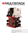
Installation and User Manual
HB Series
Package Units
& Air Handlers
• R-410A DX or Chilled Water Cooling
• Gas, Electric or Hot Water Heat
• Bottom or Side Discharge
R-410A Package
FOR YOUR SAFETY
WHAT TO DO IF YOU SMELL GAS
•
EXTINGUISH ANY OPEN FLAME
•
DO NOT TOUCH ANY ELECTRICAL SWITCH
•
DO NOT TRY TO LIGHT ANY APPLIANCE
•
DO NOT USE ANY PHONE IN YOUR BUILDING
•
IMMEDIATELY CALL YOUR GAS SUPPLIER
FROM A NEIGHBOR’S PHONE. FOLLOW THE
GAS SUPPLIER’S INSTRUCTIONS.
•
IF YOU CANNOT REACH YOUR GAS
SUPPLIER, CALL THE FIRE DEPARTMENT.
Air Handler
FOR YOUR SAFETY
DO NOT STORE OR USE GASOLINE OR OTHER
FLAMMABLE VAPORS AND LIQUIDS IN THE
VICINITY OF THIS OR ANY OTHER APPLIANCE.
WARNING
If the information in this manual is not followed
exactly, a fire or explosion may result causing
property damage, personal injury, or loss of life.
Contents
1.
Owner should pay particular attention to the words: NOTE, CAUTION, and WARNING. NOTES are
intended to clarify or make the installation easier. CAUTIONS are given to prevent equipment damage.
WARNINGS are given to alert owner that personal injury and/or equipment damage may result if installation
is not handled properly.
Important Safety Information
Thermostat
Economizer Option
Package Unit Orientation
Return Air Bypass Option
Air Handling Unit Orientation
Modulating Hot Gas Reheat
Description ………………………………...
3
Gas Piping
2.
Model Number Description ....…………..
Condensate Piping
6
Unit Model Number
6.
3.
User’s Information ……….....……………
Start-Up ……………………………..
23
General
7
DX Cooling Units (and Remote Cond. Units)
Procedures
Hydronic Cooling & Heating
Air Balancing
Gas or Electric Heating
Water Balancing
Filter Sizes
Controls
Multiple Unit Operation
Wiring Diagrams
7.
Operation & Maintenance ………..
Condensate Piping
General
Normal Thermostat Operation
Maintenance Schedule
Night and Vacancy Operation
Cooling
Gas Heating System
Condenser Fan
Hot Gas Reheat & Hot Gas Bypass System
Blower Assembly
Filter Sizes
Heating Sequence
Cabinet Construction
26
Chilled Water
Filters
4.
Delivery …………………………………….
Cleaning
10
Receipt & Inspection
Service
Storage
5.
Installation …………………………………
8.
Hot Gas Bypass (External) …..…..
28
9.
Hot Gas Reheat (Modulating) …...
28
10.
Pressure-Temperature Chart ……
31
10
General
Codes & Ordinances
Handling
Heating and Cooling Systems
Service & Installation Clearances
Setting the Unit
Electrical
Standard Control Board
Optional Control Board
Optional Control Board
Table Index:
4.1
5.1
9.1
16.1
16.2
16.3
21.1
21.2
27.1
Package Unit Dimensions
AHU Dimensions
Filter Sizes
Blink Codes: Standard Board
Blink Codes: Optional Board
Low Voltage Wiring Sizes
Minimum Gas Piping Sizes
Gas Piping Support Intervals
Filter Sizes
Figure Index
4a
5a
7a
8a
9a
9b
12a
12b
12c
Pkg. Unit Orientation
AHU Orientation
Piping Chase Location
Heat Exchangers
MHGRH+HGBP System
Foam Panel (HPCP)
Service Clearances
Airflow Clearances
Other Clearances
2
13a
14a
15a
18a
20a
22a
26a
27a
28a
Removing Shipping Brackets
Lifting Lugs and Outside Air Hood
Power and Control Wiring
External Control Inputs to Control Board
Reheated Supply Air Temperature
Gas Piping
Blower Section
Filter Section
Hot Gas Reheat System
1. Description
WARNING
Important Safety Information
RISK OF ELECTRICAL SHOCK Before attempting to perform any service or
maintenance, turn the electrical power to the unit
OFF at disconnect switch(es). Unit may have
multiple power supplies.
ONLY
QUALIFIED
PERSONNEL
SHOULD
PERFORM INSTALLATION, OPERATION, AND
MAINTENANCE OF EQUIPMENT DESCRIBED IN
THIS MANUAL.
HB series package units are designed for safe
operation when installed, operated, and maintained
within design specifications, and the instructions set
forth in this manual. It is necessary to follow these
instructions to avoid personal injury or damage to
equipment or property during equipment installation,
operation, and maintenance.
WARNING
RISK OF INJURY FROM MOVING PARTS Disconnect all power before servicing to prevent
serious injury resulting from automatic starts. Unit
may have multiple power supplies.
NOTE
WARNING
IMPORTANT!
ON 3 PHASE UNITS ONLY - Scroll compressors
will be damaged by operation with the wrong
rotation. THE LOW PRESSURE SWITCH HAS
BEEN DISCONNECTED AFTER TESTING AT
THE FACTORY. The wiring must be reconnected
and proper rotation determined at the time of startup by a qualified service technician using suction
and discharge pressure gauges. Any alteration
should only be made at the unit power connection.
This equipment is protected by a standard limited
warranty under the condition that initial installation,
service, and maintenance is performed according
to the instructions set forth in this manual. This
manual should be read in its entirety prior to
installation, and before performing any service or
maintenance work.
Units described in this manual are available with
many optional accessories. If you have questions
after reading this manual in its entirety, consult
other factory documentation, or contact your sales
representative to obtain further information before
manipulating this equipment, or its optional
accessories.
WARNING
This equipment uses R-410A only, and operates at
higher pressures than standard R-22 systems. Do
not use R-22 service equipment or tools on R410A systems. Improper use or service may result
in injuries from parts under high pressure.
WARNING
RISK OF DAMAGE, INJURY, AND LOSS OF LIFE
- Improper installation, adjustment, alteration,
service or maintenance can cause property
damage, personal injury, or loss of life. A qualified
installer or service agency must perform
installation and service.
WARNING
The Clean Air Act of 1990 bans the intentional
venting of refrigerant (CFC’s and HCFC’s) as of
July 1, 1992. Approved methods of recovery,
recycling or reclaiming must be followed. Fines
and/or incarceration may be levied for noncompliance.
3
Package Unit Orientation (Compressorized)
Service access is from the front of the unit.
As you face the front of the unit, the condensing section will be on
the right end of the unit, and the air handling section on the left.
The drain connection is located on the back.
Figure 4a, Package Unit Orientation
Return /
Outside Air /
Economizer
Section
Evaporator
Section
Filter
Section
Supply Air
Section
Controls
Section
Heating
Section
Forklift
Openings
Top Lifting Lugs
on Each Corner
Compressor
Compartment
Condenser
Section
Table 4.1, Package Unit Dimensions
Model
Width
Length
Height
002 - 005
42.25”
74.25” (93.25”)*
38”
*If present, the outside air hood will increase the overall
installed unit length by 19” for a total length of 93.25”.
4
Air Handling Unit Orientation (Non-Compressorized)
Service access is from the front of the unit.
As you face the front of the unit, the controls section will be on the
right end of the unit, and the air handling section on the left.
The drain connection is located on the back.
Figure 5a, Air Handler (Non-Compressorized) Unit Orientation
Return /
Outside Air /
Economizer
Section
Top Lifting Lugs
on Each Corner
Filter
Section
Controls
Section
Power Disconnect
Switch
Coil Section
Heating
Section
Forklift
Openings
Table 5.1, AHU Dimensions
Model
Width
Length
Height
002 - 005
42.25”
44.75” (63.75”)*
38”
*If present, the outside air hood will increase the overall
installed unit length by 19” for a total length of 63.75”.
5
2. Model Number Description
Unit Model Number
Main Features
Model
HB
Nom. Tons
-
Discharge
Location
Voltage
-
-
Cooling
Heating
-
A1
A2
A3
B1
A4
B2
:
B3
Nominal Tons
002 =
003 =
004 =
005 =
2 Tons
3 Tons
4 Tons
5 Tons
Voltage
3=
A=
B=
460V/3∅/60HZ
208-230V/1∅/60HZ
208-230V/3∅/60HZ
B1
0=
1=
2=
E=
F=
Discharge
Vertical
Horizontal
V=
H=
A1
Type*
No Heat
Electric Heat
Natural Gas Aluminized
Hot Water
Hot Water w/ Phenolic Coating
Note: LP gas and high altitude
conversion kits are available
for field installation.
Style
0=
A=
B=
No Refrigerant
R-410A
R-410A w/ 2 Step Compressor
B2
Designation
Gas Capacity
A2
Configuration
0=
2=
3=
A=
Q=
U=
W=
Y=
Z=
A3
0=
1=
2=
3=
4=
5=
No Cooling
Non-comp. w/ Std. DX Coil
Non-comp. w/ Std. DX Coil w/ RA Bypass
Air Cooled Cond. w/ Std. DX Coil
Air Cooled Cond. w/ Std. DX Coil w/ RA Bypass
Chilled Water 4 Row Coil
Chilled Water 4 Row Coil w/ RA Bypass
Chilled Water 3 Row Coil w/ 1 Row Preheat
Chilled Water 3 Row Coil w/ RA Bypass & 1 Row Preheat
B3
No Coating
Phenolic Coated Coils - Evap. & Cond.
Phenolic Coated Condenser Coil Only
Phenolic Coated Evaporator Coil Only
Staging
0=
1=
2=
M=
N=
No Cooling
Single Stage
Dual Stage (w/ 2 step compressor)
Single Serpentine Chilled Water
Half Serpentine Chilled Water
6
No Heat
45
60
75
100
125
Electric Capacity
kW 208V
7.5
15
22.5
-
Staging
0=
1=
2=
3=
M=
N=
Coating
0=
1=
8=
9=
A4
Mbtu
No Heat
1 Stage (Gas or Electric)
2 Stage (Gas or Electric)
3 Stage (Electric Only)
Single Serpentine (Hot Water)
Half Serpentine (Hot Water)
kW 240-480V
10
20
30
-
air temperatures (typically air temperatures below
40°F) that could cause coils to freeze.
3. User’s Information
WARNING
Figure 7a, Piping Chase Location
Failure to observe the following instructions may
result in premature failure of your system, and
possible voiding of the warranty.
Utility Entry
4” x 2 1/2”
Shipping
Bracket
Piping Chase
4” x 7”
Front
DX (Direct Expansion) Package Units and DX
Units with Remote Condenser
Never cut off the main power supply to the unit, except
for complete shutdown.
Supply
Return
Always control the system from the thermostat, or
control panel, and never at the main power supply
(except in an emergency, or complete shutdown of the
system).
Back
During the cooling season, if the airflow is reduced due
to dirty air filters, or other reasons, the cooling coils will
get too cold and result in excessive liquid return to the
compressor. As the liquid concentration accumulates,
oil is washed out of the compressor leaving it starved
for lubrication.
Gas or Electric Heating
The system is designed to heat a given amount of air
each minute of operation. If the amount of air heated
is greatly reduced (approximately 1/3 capacity), the
heat exchanger (or heater coil if electric) temperature
will increase above acceptable levels, and will result in
shut down by a high temperature safety switch
incorporated into either the heat exchanger, or the
heater area.
The compressors must be on a minimum of four
minutes, and off for a minimum of five minutes. The
cycle rate must not exceed eight starts per hour.
THE COMPRESSOR LIFE WILL BE SERIOUSLY
SHORTENED
BY
RESULTING
REDUCED
LUBRICATION, AND THE PUMPING OF EXCESS
AMOUNTS OF LIQUID OIL AND REFRIGERANT.
WARNING
GAS HEAT UNITS – If heat shuts off due to safety
switch, or gas supply shut off failure, then always
close manual gas valve to unit prior to any
electrical service. Prolonged overheating of the
heat exchanger will shorten its life.
Hydronic Cooling and Heating
Non-compressorized units may contain chilled water
and/or hot water coils. Units are provided with internal
header connections for field piping. Vent and drain
connections can be accessed within the unit.
Piping is to be run via the 4” x 7” piping chase located
in the cabinet floor inside the coil compartment,
accessible through the coil compartment access door
on the front of the unit. Piping to coil header
connections must be supported independently of the
coil to prevent undue stress from weakening
connections over time. Allow adequate flexibility for
thermal expansion of the piping.
WARNING
Improper installation, adjustment, alteration,
service, or maintenance can cause property
damage, personal injury, or loss of life. Installation
and service must be performed by a qualified
installer, service agency, or if gas fired units, the
gas supplier. Refer to installation instructions
provided with the unit, and this manual.
Use proper glycol solutions or brines to help prevent
coil freezing. Consult the designer or project engineer
if you have concerns about lower than normal entering
7
Multiple Unit Operation
Night and Vacancy Operation
When several units are used in conditioning the space,
and any are combination heating-cooling units, all
system thermostat switches must be set at either
heating, cooling, or set at ‘OFF’. Do not run part of a
system switched to an opposite mode. Cooling only
units should be switched to ‘OFF’ at the thermostat
during the heating season.
To reduce the operation time during low load periods,
it is recommended that the temperature setting be
increased by 5°F during non-occupied periods of the
cooling season in commercial buildings, such as nights
and weekends. Decrease the temperature by 10°F at
these times during the heating season.
Gas Heating System
Wiring Diagrams
The heating section is for use with natural gas supply
pressure of 6” to 10.5” w.g. The unit may also utilize
propane gas (after installation of a field conversion kit)
with a supply pressure to the valve of 11” to 12” w.g.
The rating plate on the furnace must be inspected to
make sure the unit is stamped for proper gas. A 1/8”
pressure tap should be field supplied by the installer in
the piping just ahead of the gas valve. The pressure
tap on the outlet end of the gas valve can be checked
to verify manifold pressure of 3.2” to 3.5” w.g. for
natural gas or 11” to 12” w.g. for propane.
A complete set of unit specific wiring diagrams in both
ladder and point-to-point form are laminated in plastic
and affixed to the inside of the service access door.
Condensate Piping
A drain trap must be connected to the drain connection
located on the back of the unit. If codes require a
condensate drain line, it should be the same pipe size
as the drain nipple and should pitch downward for its
entire length toward the drain.
A “P” Trap is factory supplied and shipped in the
control access compartment for field installation. An
air break should be used with long runs of condensate
lines.
A centrifugal blower that draws in outside air through a
protected
opening
supplies
combustion
air.
This induced draft blower introduces the air to the
blower tubes, which assures even primary and
secondary airflow.
Normal Thermostat Operation
Gas heating units use AAON’s patented high efficiency
twisted tube, or dimpled heat exchanger. All heating
system and related safety controls are 100% tested on
each unit prior to shipment.
For Heating
-
Set system switch to ‘HEAT’
Set fan switch to ‘AUTO’ or ‘ON’
Set the desired temperature
Figure 8a, HB Gas Heat Exchangers
Twisted Tube
For Cooling
-
Set system switch to ‘COOL’
Set fan switch to ‘AUTO’ or ‘ON’
Air Circulation
-
Set the system switch to ‘OFF’
Set the fan switch to ‘ON’
Dimpled Tube
System Off
-
Set the system switch to ‘OFF’
Set the fan switch to ‘AUTO’
Do not change temperature setting
With these settings the system is shut down,
except for the 24-volt control system power, and
the compressor crankcase heater (approx. 60W).
8
Filter Sizes
Modulating Hot Gas Reheat and Hot Gas
Bypass Systems on DX Units
Table 9.1, Pleated Filter Sizes
Some DX cooling units may contain Modulating Hot
Gas Reheat (MHGRH) and/or Hot Gas Bypass
(HGBP) systems as factory installed options. Piping
and valves for these systems will be located on the
inside wall of the condenser section. The condenser
top must be removed for access to these components.
All 2-5 Ton HB Packaged Units
Figure 9a, MHGRH and HGBP System
Piping to
Compressor and
Coil Compartments
Qty.
Size
2
20” x 25” x 2”
Cabinet Construction
HGBP
Valve
All HB units are insulated with closed-cell polyurethane
foam, which has twice the R-value of fiberglass
insulation. All cabinet walls and roof use double-wall
G90 galvanized steel. The solid core foam interior
provides a rigid, impact resistant surface. All panels
have a thermal break with no metal-to-metal contact
from outside to inside.
Figure 9b, High Performance Composite Panel
Thermal Break
Foam Core
Double-Wall
Receiver
Tank
Check
Valve
MHGRH
Valves
9
4. Delivery
5. Installation
ALL SHIPMENTS ARE F.O.B. THE FACTORY. IT IS
THE RESPONSIBILITY OF THE RECEIVING PARTY
TO INSPECT THE EQUIPMENT UPON ARRIVAL.
General
DX models of this unit use R-410A refrigerant only,
and should not be used with any other refrigerant. HB
package units are for outdoor installation only.
Receipt & Inspection
The unit should be inspected for damage that may
have occurred in transit. Do the following upon
receipt:
Codes & Ordinances
System should be sized in accordance with National
Warm Air Heating and Air Conditioning Association
Literature, or the Guide of American Society of
Heating, Refrigeration and Air Conditioning Engineers.
The installation must conform with local building
codes, or in the absence of local codes, with (United
States) National Fuel Gas Code “ANSI-Z223.1”,
(Canada) current CAN/CGA-B149.1 or B149.2.
Installation codes for Gas Burning Appliances and
Equipment, current C.S.A. Standard C22.1, Canadian
Electrical Code Part 1, and C.S.A. Standard B52
Mechanical Refrigeration Code, and Local Plumbing or
Waste Water Codes.
1. Inspect all items for internal, external, and
concealed damage before accepting
2. Assure carrier is in compliance with Bill of
Lading instructions
If damage is found:
1. Note all damage on Bill of Lading immediately
− Photograph damage if possible
− Do not move or discard damaged
packaging materials
2. Call carrier immediately to file a freight claim,
and to schedule a freight inspection
3. When damage is repairable, contact the
factory for replacement parts: 918-583-2266
4. With permission of carrier, make the repairs
5. Stay in contact with carrier to ensure payment
of your claim
WARNING
It is the responsibility of the installing contractor to
comply with codes, ordinances, local and
municipal building laws, and manufacturer’s
instructions. Personal injury and/or equipment
damage may result if proper procedures are not
followed.
If repairs must be made to damaged goods, the factory
must be notified before any repair action is taken.
Equipment alteration, repair, or unauthorized
manipulation of damaged equipment without the
manufacturer’s consent will void all product warranties.
Contact the AAON Warranty Department for
assistance with handling damaged goods, repairs, and
freight claims: 918-583-2266.
Handling
Be aware of what is contained in the equipment!
Verify the equipment against the order documents
upon delivery. If what you received does not match
your order exactly, then notify your Sales
Representative at once.
Dependent upon the optional accessories that were
ordered, this equipment may contain fragile
components and delicate electronics. Although the
unit is constructed of sturdy materials, avoid impacts
and handling methods that may damage internal
apparatus and structure, or the exterior painted
surfaces of the unit. Take care not to apply destructive
force to coils, or other parts protruding beyond the
extents of the unit casing. Always handle the unit by
its exterior casing.
Storage
This equipment is designed for outdoor use. However,
if installation will not occur immediately following
delivery, then store equipment in a protected area, and
in the proper orientation as marked on the packaging
with all internal packaging in place. Secure all looseshipped items.
Keep equipment free from debris, and construction
waste during installation.
Foreign materials may
adversely affect unit operation resulting in premature
failures that will not be covered by the manufacturer’s
10
ELECTRIC HEATING SYSTEM
warranty. Attach all service panels, and cover all
exposed equipment when work is not being performed.
Leave unit protected from other construction until startup is to occur.
Heating is accomplished by passing electrical current
through a specified amount of resistance heaters that
produce the required heat. The indoor blower motor
energizes at the same time as the heaters.
WARNING
DX COOLING SECTION
Always wear hand and eye protection when
handling, installing, servicing, or maintaining
equipment. Sharp or pointed edges, moving parts,
and flying debris may cause personal injury.
All direct expansion refrigeration systems are factory
assembled, charged with refrigerant, tested, and
operated. These systems include liquid line filter
driers, expansion valves, and fully hermetic scroll
compressors. Compressors are equipped with a
positive pressure forced lubrication system. The aircooled condenser coil is constructed of copper tubes
and mechanically bonded aluminum fins, and air is
pulled through by a propeller fan. The evaporator coil
is draw through type constructed of copper tubes and
mechanically bonded aluminum fins.
Heating & Cooling Systems
GAS HEATING SYSTEM
The units are equipped with a direct spark ignition
system that proves the burner operation with each call
for heat. Power to the ignition control is 24V to reduce
hazards. Burner ignition is by a high intensity spark.
These appliances have been found acceptable with
applicable provisions of “ANSI/UL 1995” and current
“C.S.A. Standard C22.2” by E.T.L.
When heat is called for, the cooling system is
inoperable except for the indoor blower motor.
Heating is accomplished by firing gas into the heat
exchanger assembly.
CHILLED WATER or NON-COMPRESSORIZED
COOLING SECTION
Chilled water, or non-compressorized units, have
factory-installed coils. Systems are provided with
internal header connections for field piping.
WARNING
Coils are constructed of copper tubes and
mechanically bonded aluminum fins.
Those sensitive to odors or gases from trace
amounts of residual oils should NOT be present in
the conditioned space during the start-up of a gasfired installation.
CAUTION
DO NOT DRILL OR PUNCH HOLES IN THE UNIT
– The walls of this unit are foam insulated. Field
modifications to the unit casing may compromise
the unit’s superior insulating capability, in which
case excessive leakage, or condensation may
occur.
IMPORTANT NOTICE - All gas-fired heat exchangers
are completely tested at the factory before shipment.
This will remove nearly all of the oils that have been
used in the manufacturing process, however trace
amounts may remain. When performing the initial
start-up at the jobsite it is highly recommended that
people, or any other living animals, that may be
sensitive to the residual odors or gases, NOT be
present in the conditioned space during start-up. In all
cases, including the initial factory firing and testing, all
of the gases will be under the minimum acceptable
level of concentration for human occupancy.
WARNING
Very high temperatures can damage foam core
insulation. High heat may cause off gassing of
harmful fumes. Do not apply direct flame to unit
cabinet.
11
Service & Installation Clearances
Figure 12b, Airflow Clearance Minimums
Before setting the unit into place, caution must be
taken to provide clearance for unit panels/doors that
must be accessible for periodic service. These areas
contain the controls, safety devices, refrigerant, shutoff valves and filter access.
Adjacent
Condenser
HB package units have minimum service and airflow
clearance requirements.
48”
Air In
Service Clearance Minimums:
Air In
- 36 inches to the front
- 10 inches to the back
- 20 inches to right and left ends
10”
Condenser
Airflow
Minimum 20”
Clearance
20”
Air Out
Airflow Clearance Minimums:
Air In
- 20 inches around the entire condenser intake
- 24 inches between condenser and obstructions
- 48 inches of clearance over the condenser air
discharge, and from adjacent condenser intakes
Air In
SA
RA
Figure 12a, Service Clearance Minimums
Wall or Obstruction
Back
RA
HB Package Unit
SA
10”
Air In
Figure 12c, Other Airflow Clearance Minimums
Air Out
20”
Air In
Left
Right
20”
Required condenser
clearance doubles to 40
inches in recessed areas.
Air In
48”
36”
Service Access Clearance
Air Out
Front
40”
Airflow to and from the condensing unit must not be
restricted. Obstruction to airflow will result in
decreased performance and efficiency.
The
installation position must provide at least 20 inches
of condenser clearance for proper airflow into the
condenser coil. When the unit’s condenser is
positioned adjacent to another condenser, 48
inches of clearance is required between air intakes
for proper airflow and operation.
The HB package unit has a vertical air discharge.
There must be at least 48 inches of clearance
above the vertical air discharge. There must not be
any obstruction above the equipment that may
deflect discharge air back into the unit’s air inlets.
It is advisable to never place the unit directly under
an overhang. Condensing units should not be
installed in an enclosure or pit that is deeper than
the height of the unit. When the unit is installed in
a recessed area the coil side clearance is doubled
to 40 inches for inlet air.
12
Setting the Unit
NOTE
Units should always be installed level, and above
water drainage routes. Unit operation can be affected
by wind. It is good practice to position unit condensing
sections away from prevailing winds.
PRIOR TO SETTING UNIT ON CURB – To ensure
proper isolation and seal between the unit and the
curb, gasket material MUST BE APPLIED to the
curb on ALL SURFACES meeting with the unit.
Protective Shipping Brackets
Before setting the unit into its final position on the slab
or curb, be sure to remove the protective shipping
brackets, or “bumpers” from the perimeter of the unit’s
base.
Hoisting
Figure 13a, Removing Shipping Brackets
If cables or chains are used to hoist the unit, they must
be the same length, and care should be taken to
prevent damage to the unit.
Lifting lugs are provided on each corner of the top of
the unit.
It is recommended that the unit be hoisted with the
outside air hood (if present) in the shipped position.
However, the unit may be hoisted with the outside air
hood in an open position.
Before lifting unit, be sure that all shipping material is
removed. Secure hooks and cables at all lifting
points/lugs provided on the unit.
Prior to setting the unit onto the roof curb, be sure that
the gasket material has been applied to all curb
surfaces meeting with the unit.
Hoist unit to a point directly above the curb and duct
openings. Carefully lower and align the unit’s utility
and duct openings so the unit perimeter fits around the
curb. Make sure the unit is properly seated on the
curb and is level.
Outside Air Hood (Optional)
Ground Setting
Units equipped with outside air intake will have an
outside air hood. The outside air hood must be
opened prior to unit operation.
Set the unit on a solid slab high enough above the soil
grade to allow water to drain away from the base of
the unit. The unit should be set on a slab that has
been placed over compact, level earth. A poured
concrete (permanent) slab is recommended.
Remove shipping screws from each side of the hood in
the “closed” position. Lift hood to the “open” position,
seal flange, and secure with sheet metal screws.
Roof Setting w/ Curb
Outdoor air intake adjustments should be made
according to building ventilation, or local code
requirements.
Mount roof curbs first, and locate so duct connections
will clear any structural members of the building.
When using the factory curb, make openings in roof
decking large enough to allow for duct penetrations
and workspace only. Do not make openings larger
than necessary. Set the curb to coincide with the
openings. CURB MUST BE LEVEL.
13
Electrical
Figure 14a, Lifting Lugs and Outside Air Hood
Check the unit data plate to make sure it matches the
power supply. Connect power to the unit according to
the wiring diagram provided with the unit. The power
and control wiring may be brought in through the utility
entry. Do not run power and control wires in the same
conduit.
Lifting lug on each corner
Protect the branch circuit in accordance with code
requirements. The units must be electrically grounded
in accordance with the National Electric Code, ANSI /
NFPA No. 70. In Canada use current C.S.A. Standard
C22.1, Canadian Electric Code Part 1.
Connect power wiring to the terminal block, or optional
disconnect switch. The manufacturer has done all
wiring beyond this point, and cannot be modified
without affecting the unit’s agency and/or safety
certification, and warranty.
Power can be applied to the unit after the control
wiring is connected.
Outside Air Hood (Optional)
Standard Control Board
This printed circuit board is the central control point for
all the electrical components in the unit. Low voltage
terminals are provided for connection to the wall
mounted thermostat of the customer’s selection, or as
furnished by AAON.
CAUTION
If the supply or warm air duct passes through a
combustible roof, a clearance of one inch must be
maintained between the outside edges of the duct
and combustible material in accordance with
National Fire Protection Association Standard No.
90A. Provide flashings or enclosure between
structure, and roof. All joints must be sealed with
mastic to ensure a watertight seal.
Confirm the optional features that were specified and
purchased with the HB conditioner. This will allow
proper selection of the number of control options listed
below that may need additional wiring.
All roofing work should be performed by qualified
roofing contractors.
WARNING
Install gas fired units so that the flue discharge
vent is located a minimum of 120” from openings
through which combustion products can enter the
building. Never point flue discharge in direction of
air intake for other equipment. Unit location must
assure combustion and ventilation airflows are
never obstructed.
14
Figure 15a, Power and Control Wiring
Compressor and Control Compartment
Standard Control Board
Red, yellow and green LEDs for
fault, mode, and power indicators.
Standard Control Board has low
voltage terminals for R, G, Y1, Y2,
W1, W2, W3 & GND. GND is the
ground, or “C” side of the low
voltage power supply transformer.
Optional Control Board
Optional Control Board has
expanded capability to support
optional unit features.
Connect control wiring to low
voltage terminal block.
Power Terminal Block
Utility Entry
Run power supply wiring in conduit
through utility entry to terminal block.
Low voltage control wiring must run
through separate conduit from power
wiring.
Connect power wiring to terminal
block, or the optional disconnect
switch next to compressor.
15
Table 16.2, Optional Control Board Blink Codes
Each HB has a standard Cooling Lock-out feature that
prevents the compressor cooling mode when the
outdoor temperature is below 55°F. Each unit also
has a condenser fan cycle feature that delays the start
of the condenser fan until there is satisfactory
compressor discharge pressure.
Optional Control Board Blink Codes
Red LED
Fault Condition
Hi Safety Lockout
Hi Pres Lockout
Lo Pres Lockout
Bad Supply Air Temp Sensor
Bad Outdoor Air Temp Sensor
Clogged Filter
Three colored LEDs are furnished on the circuit board
immediately above the low voltage terminals to provide
status information as listed in the Table 14.1.
Every unit is furnished with a high and low pressure
sensor, as well as an outdoor air temperature sensor.
These sensors provide a signal to the control board
that also present a fault condition or Mode indicator at
the LEDs with a blink rate code.
Blinks
1
2
3
4
5
7
When no fault exists, red LED is off.
Lowest number is highest priority.
Yellow LED
Mode Indicator
Vent Mode
Heating Mode
Cooling Mode
Economizer Cooling
Dehumidification Mode
Economizer Dehumidification Mode
Blink Rate:
1 second ON and 1 second OFF.
3 seconds OFF before repeating.
Blinks
1
2
3
4
5
6
When unit is off, yellow LED is off..
Table 16.1, Standard Control Board Blink Codes
Green LED
Power Status Only – Blinking Indicates Communications
Standard Control Board Blink Codes
Red LED
Fault Condition
Hi Pres Lockout
Lo Pres Lockout
Bad Outdoor Air Temp Sensor
Clogged Filter
Blinks
2
3
5
7
Thermostat
The low voltage room thermostat should be located on
an inside wall 4 to 5 feet above the floor where it will
not be subjected to drafts, sun exposure or heat from
electrical fixtures or appliances. The control wire size
must be large enough to prevent excess voltage drop
that may cause improper operation of the equipment.
The HB control board has approximately a 1/2 amp
current flow through the thermostat. Follow the
thermostat manufacturer’s instructions to set the heat
anticipator.
When no fault exists, red LED is off.
Lowest number is highest priority.
Yellow LED
Mode Indicator
Vent Mode
Heating Mode
Cooling Mode
Blinks
1
2
3
When unit is off, yellow LED is off.
Table 16.3, Low Voltage Thermostat Field Wiring Size
Green LED
Power Status Only – Blinking Indicates Communications
Length of Wire Run
Optional Control Board
This Control Board is supplied within the HB Model
when it has been furnished with certain optional
features specified by the customer. Among these are
an Economizer, Return Air Bypass, and Hot Gas
Reheat.
T-stat Load Amps
50 Ft.
100 Ft.
150 Ft.
HB - Less than 1.0
18ga.
18ga.
16ga.
Single Stage Heating & Cooling
The R, G, Y & W terminals on a single stage
thermostat should be connected to the similarly
labeled terminals on the Control Board in the HB unit.
16
2 Step Compressor Cooling Models
Factory Installed
−
The HB models with a 2 step cooling compressor
may use a 2 step cooling thermostat with the R, G,
Y1, Y2 & W terminals connected to the similarly
labeled terminals on the Control Board in the HB
unit.
−
These HB models can also be connected to a
single step cooling thermostat with the Y terminal
on the thermostat connected to the Y2 terminal on
the Control Board in the HB unit. A built-in time
delay in the Control Board will cycle the 2 stages
of cooling as required.
When factory installed the control board will use the
outdoor air sensor and the cooling signal from the
thermostat to provide a first stage of cooling using the
outside air when possible before starting the
compressor and mechanical cooling cycle.
The
thermostat wiring to the control board with single or
multi-stages should be wired as listed previously.
Field Installed
When the control is field installed the 2 to 10 VDC
signal for the economizer damper motor must be wired
to the Control Circuit Board in the HB unit. See Figure
18a. Note that the jumper must be moved to the
“external” position and the signal wired to the ECONO
POS and GND terminals on the control board.
Multiple Stage Heating
−
−
HB models with 2 or 3 stage heating should have
the W1, W2 and W3 terminals on the thermostat
connected to the similarly labeled terminals on the
Control Board in the HB unit.
Return Air Bypass Option
The Return Air Bypass option is used to provide
additional moisture removal capacity to the HB unit.
For this application a humidistat must also be installed
in the conditioned space to provide a signal to initiate
the dehumidification.
The humidistat may be
purchased from AAON or from others.
These models can also be connected to a single
step heating thermostat with the W terminal on the
thermostat connected to the W2 terminal on the
Control Board in the HB unit for 2 step heating or
the W3 terminal for 3 step heating. A built-in time
delay in the Control Board will cycle the stages of
heating as required.
A return air bypass control system by others may be
field installed as selected by the customer instead of
factory installed by AAON.
Programmable Thermostats
Factory Installed
If a programmable thermostat be used, then the C
terminal on the thermostat should be connected to the
C or GND terminal on the Control Board.
The control board in the HB unit must be wired to the
humidistat in the occupied space at the R and RH
terminals. The thermostat wiring to the control board
with single or multi-stages should be installed as listed
previously.
Economizer Option
The economizer option is used to provide cooling at
lower outdoor air temperatures and to provide a
quantity of ventilation air to the occupied space. The
economizer option can be selected with either a
sensible outdoor air temperature sensor or an enthalpy
sensor that measures the heat content in the outdoor
air. The economizer controller can be field installed or
factory installed by AAON as selected by the
customer.
When the Humidistat is calling for moisture removal
from the occupied space, the compressor will operate
with the return air bypass damper in the open position
and the supply fan running in the low speed mode. If
the Thermostat calls for cooling, the bypass damper
will close and the fan will operate at high speed until
the thermostat is satisfied.
Field Installed
Supply Air Temperature Sensor
When the control is field installed, the 0 to 10 VDC
signal for the return air bypass damper motor must be
wired to the Control Circuit Board in the HB unit. See
Figure 16a. Note that the jumper must be moved to
the “external” position and the signal wired to the RAB
and GND terminals on the control board.
A supply air temperature sensor is factory wired and
provided within the equipment at the end of a coil of
wire. This sensor must be installed in the downstream
supply air ductwork at a sufficient distance from the
equipment to provide a correctly mixed supply air
temperature back to the unit control board.
17
Figure 18a, External Control Inputs to Control Board
18
Modulating Hot Gas Reheat
Example:
We want the Discharge Air Temperature Setpoint to
increase from 55°F when the Reset Input signal is at 0
Volts, to 75°F when the Reset Input signal is at 10
Volts.
• Set the SETPOINT DIP Switch to 55°F
• Set the RESET LIMIT DIP Switch to 75°F
The modulating hot gas reheat option is used to
provide additional moisture removal capacity to the HB
unit.
Hot refrigerant gas discharged from the
compressor is sent as needed to a reheat coil
mounted immediately after the cooling coil.
For this application a humidistat must also be installed
in the conditioned space to provide a signal to initiate
the dehumidification by operating the hot gas reheat to
deliver dehumidified air at a specified temperature into
the occupied space.
The humidistat may be
purchased from AAON or from others. The thermostat
wiring to the control board with single or multi-stages
should be installed as listed previously.
The discharge air temperature will now increase from
55°F to 75°F as the Reset Input voltage signal ramps
from 0 Volts to 10 Volts.
Note: It is possible to create a “reverse acting” control
sequence. Using the temperatures from the example
above by setting the SETPOINT DIP Switch to 75°F
and the RESET LIMIT DIP Switch to 55°F the reset
would be reverse acting. In this case the controller will
maintain a 75°F discharge temperature when the
Reset Input signal is at 0 Volts and will reduce it to
55°F when the Reset Input signal is at 10 Volts.
Supply Air Temperature Sensor
A supply air temperature sensor is factory wired and
provided within the equipment at the end of a coil of
wire. This must be installed in the downstream supply
air ductwork at a sufficient distance from the
equipment to provide a correct mixed air temperature
to the unit control board.
Lockout Modes
Gas Heating
Reheated Supply Air Temperature
The heating mode will be locked out if the ignition
system safety monitors trip 3 times during a call for
heating.
The desired discharge air temperature setpoint can be
preset and later adjusted by using the DIP switch
labeled SETPOINT on the circuit board. See Figure
18a for the location and DIP switch setting instructions.
The controller will allow the user to set a Supply Air
Temperature Setpoint between 50°F and 100°F. If a
value of less than 50°F is set, then the controller will
default to a 50°F Supply Air Temperature Setpoint. A
value greater than 100° F will cause the unit to default
to a 100°F Supply Air Temperature Setpoint.
Electric Heating
The heating mode will be locked out if the high
temperature limit switch trips 3 times during a call for
heating.
Cooling
Supply Air Temperature Reset Limit
The cooling mode will be locked out if the low pressure
switch safety switch trips 3 times during a call for
cooling or dehumidification.
The controller will also allow a reset of the temperature
by a 0 to 10 VDC signal from an outside source to the
terminal as shown in Figure 18a. The reset range is
determined by the setting configured on the DIP switch
labeled RESET LIMIT. The controller will reset the
supply air temperature setpoint from the value set on
the SETPOINT DIP switch to the value set on the
RESET LIMIT DIP switch, as the Reset Input (MHGRV
RSET) signal is increased from 0 Volts to 10 Volts.
Cooling operation will be locked out if the Outside Air
Sensor is missing or defective.
The economizer and reheat operation during
dehumidification will be locked out if the Supply Air
Sensor is missing or defective.
To reset the lockout condition, either remove the call
for heating, cooling, dehumidification, or cycle the
power to the HB unit.
19
Figure 20a, Reheated Supply Air Temperature
20
Gas Piping
Table 21.2, Gas Piping Support Intervals
Size gas piping to supply the unit with 6” to 10.5” water
column (w.g.) pressure for natural gas, or 11” w.g. for
propane (when a natural gas to propane conversion kit
has been field installed) when all gas consuming
devices in the building connected to the same gas
system are operating. Install piping in accordance with
local codes, the piping must conform with the latest
ANSI-Z223.1 National Fuel Gas Code; in Canada,
Current Standard CAN/CGA-B149, Installation for Gas
Burning Appliances and Equipment.
CAUTION
Some soaps commonly used for leak detection are
corrosive to certain metals. If you leak test with
soap, then thoroughly rinse soap from piping after
leak checks are completed.
All piping connections should be checked for gas leaks
before operating the unit. The furnace must be
isolated by closing the manual shut off valve, or
disconnected from the gas supply during pressure
testing of the piping system with pressures in excess
of 1/2 PSIG.
Gas Pressure Regulator & Over-Pressure
Protection Device (Optional)
WARNING
Those sensitive to odors or gases from trace
amounts of residual oils should NOT be present in
the conditioned space during the start-up of a gas
fired installation.
On applications where gas service to the unit is
greater than 10.5” w.g., and less than 2 PSI, a gas
pressure regulator must be installed.
In compliance with the ANSI Z21.80 Line Regulator
Standard, installations with gas supply pressures in
excess of 2 PSI, and less than 5 PSI require a tested
and approved over-pressure protection device (OPD)
for use with the regulator as a means to limit the
downstream pressure to 2 PSI maximum in the event
of regulator failure.
For proper heating operation, pressure to the regulator
MUST NOT BE greater than 5 PSI.
Table 21.1, Minimum Gas Piping Sizes
Pipe Size (In.)
2–5
45 – 120
3/4
8
10
Every floor level
DO NOT USE OPEN FLAME OR OTHER
SOURCE OF IGNITION FOR LEAK TESTING.
When pressure testing the gas supply piping, the
furnace must be isolated, or disconnected by
closing the individual manual shut-off valve from
the gas supply. Gas valves can be damaged if
subjected to more than 0.5 PSIG pressure.
Pipe joint compounds used on all gas piping
connections must be resistant to the action of
petroleum gases. A 1/8” NPT plugged tap is required
immediately ahead of the unit gas control valve.
Input (MBH)
Intervals (Ft.)
WARNING
Gas piping MUST BE supported DIRECTLY AT
CONNECTION TO UNIT, and must not be strained or
bent, and must be supported by metal straps, blocks,
or hooks at intervals not to exceed that shown in Table
21.2.
Unit Size (Tons)
Pipe Size (In.)
3/4 or 1 (horizontal or vertical)
1 1/4 or larger (horizontal)
1 1/4 or larger (vertical)
Note: Some utility companies will require pipe sizes larger than the
minimum listed above. Local codes may require the use of a
manual main gas shut-off valve and union (field furnished),
installed in the gas line external to the unit.
21
Figure 22a, Gas Piping
Gas Valve
Valve Inlet
Piping to gas valve inlet must
be completed in field.
Gas valve installed at factory.
Sidewall
Entry
Bottom or Side Utility
Entry Options
Run piping through utility entry in front of unit,
or through entry in floor of unit located next to
the compressor. Then run piping through
sidewall into heating cabinet.
Remember to seal around all exterior cabinet
penetrations at utility entries.
Piping assembly ready to connect to field
supplied gas line.
22
Condensate Piping
6. Start-Up
HB package units are equipped with a condensate
drain connection, and ‘P’ traps are furnished with the
equipment. The drain connection must be used and
individually trapped to ensure a minimum amount of
condensate accumulation in the drain pans.
General
ONLY QUALIFIED, AUTHORIZED PERSONNEL
SHOULD POWER ON, OR START-UP THIS
EQUIPMENT.
Although drainage of condensate directly onto the roof
may be acceptable in certain areas, is not
recommended as it can damage some types of
roofing, and roofing materials. Refer to local codes for
legalities concerning condensate drainage.
The use of common sense, and good practice in the
installation, and start-up of equipment will prevent
many potential problems with the system in the future.
Before starting up the equipment, building construction
should be complete, and start-up personnel should:
Condensate can be piped to a gutter system, or away
from the building into other drainage.
Ideally,
condensate will be piped into the building drainage
system, in which case the drainpipe may need to
penetrate the roof external to the unit itself.
−
−
The drain line should be pitched away from the unit
with at least 1/8” of slope per foot. On longer runs, an
air break should be used to ensure proper drainage.
−
Drain pans in air conditioning equipment have
moisture present and require periodic cleaning to
remove build up of algae, and/or bacteria. Cleaning
the drain pans reduces the probability of plugged drain
lines and overflow of the pan itself. All cleaning of the
drain pans and inside of the equipment should be
done by qualified personnel.
Have a working knowledge of general HVAC
and mechanical commissioning procedures
and practices;
Be familiar with unit functions, features,
optional unit accessories, and all control
sequences;
Have appropriate literature on hand for
consultation.
Procedures
CAUTION
Equipment operation during construction is not
recommended. Construction site pollution can
affect unit operation, and seriously degrade
performance. Operation during construction will
void all manufacturer’s warranties.
Before the structure is occupied, the installation,
and/or start-up personnel must take three essential
steps:
1. Pre-Startup Check Out
2. Start-Up
3. Commissioning
Pre-Startup Check Out
All equipment should be thoroughly checked for loose
wiring, free spinning condenser fan and blower wheel,
and well fitting access panels. Unit should not be
operated without proper ductwork, and access panels
installed, except as required during start-up and air
balancing.
Install gauges, voltmeter, and ammeter before startup. Observe refrigerant pressures during initial
operation. Note, and determine the cause of any
23
excessive sound, or vibration. Follow procedures
outlined below to start each piece of equipment.
Before powering on, or starting the unit:
DX Cooling:
1. Ensure that drain P-trap is installed.
2. Turn the unit power on.
3. Turn the unit blower on, and check for correct
rotation.
4. If correct, take blower amp readings, and
compare to see if the amp draw is within the
safety factor area of the motor.
5. Check and record ambient temperature.
6. Start the first stage cooling circuit, and blower
circuit.
7. After all stages of cooling have been on for at
least five minutes, record the return air
temperature, and supply air temperature.
8. Check the temperature difference across the
evaporator coil.
9. If equipped with an economizer, after testing
of cooling circuits is complete, turn cooling
circuits off, and leave blower running.
10. Call for the economizer circuit to operate.
11. Check for economizer blades to open fully with
no binding.
1. Check the unit for external damage.
2. Note all accessories installed.
3. Ensure all field and factory high and low
voltage electrical connections are correct, and
tight.
4. Check all terminal blocks, fuses, fuse blocks,
and contactors for correctness
5. Open all access panels, and remove all
shipping screws, or restraints.
6. Remove any debris that may have been left.
7. Ensure electrical supply matches the unit
nameplate.
8. Ensure condensate lines are connected and
glued.
9. Install air filters of the proper size and type.
10. Check local codes for any special provisions.
11. Replace, and/or close all access panels.
12. Ensure that return, and/or supply dampers in
ductwork are open.
13. Check all equipment, ductwork, and piping to
verify that all work is complete, and equipment
is properly installed and mounted.
Gas Heating:
1. Ensure that gas lines have been purged of air
– wait 5 minutes after purging to allow gas to
clear before continuing with startup.
2. Turn the unit power on.
3. Turn the unit blower on, and check for correct
rotation.
4. If correct, take blower amp readings, and
compare to see if the amp draw is within the
safety factor area of the motor. Once correct,
turn blower off.
5. Check gas input and manifold pressure, and
adjust if necessary.
6. Turn on the first stage of heating.
7. Check to see that induced draft motor starts.
8. Check to see that main burner lights within 5
seconds of the heating call.
9. Ensure blower started after burner ignition.
10. Observe burner flames for light blue color, and
even flames across burner (propane flames
will have yellow tips).
11. Check temperature rise across heating section
while all stages are on.
12. If temperature rise is within range, turn all
heating calls off.
13. Check that blower stops after heat turns off
Start-Up
NOTE
Failure to adhere to the following start-up
procedures will void all manufacturer’s warranties.
NOTE
Completed factory test sheets are in the equipment
literature packet shipped inside the unit. Factory
run-test readings recorded on the test sheets may
be helpful to reference during start-up.
CAUTION
IMPORTANT FOR 3 PHASE UNITS ONLY!
CHECK
COMPRESSOR
FOR
PROPER
ROTATION BY STARTING UNIT ONLY AFTER
CONNECTING
PRESSURE
GAUGES
TO
SUCTION AND DISCHARGE LINES. SCROLL
COMPRESSORS WILL BE DESTROYED IF
OPERATED IN THE WRONG DIRECTION.
24
Electric Heating:
Water Balancing
1. Turn the unit power on.
2. Turn the unit blower on, and check for correct
rotation.
3. If correct, take blower amp readings, and
compare to see if the amp draw is within the
safety factor area of the motor. Once correct,
turn blower off.
4. Turn on the first stage of heating.
5. Check amp draw of each element of each
stage.
6. Ensure blower started with heat.
7. Check temperature rise across heating section
while all stages are on.
8. If temperature rise is within range, turn all
heating calls off.
9. Check to see that blower stops.
A hydronic specialist with a complete working
knowledge of water systems, controls, and operation
must be employed to properly balance the entire
system. Unqualified personnel should not attempt to
manipulate temperatures, pressures, or flow rates, as
all systems have unique operating characteristics, and
improper balancing can result in undesirable noises
and operation.
Controls
A variety of controls and electrical accessories may be
provided with the equipment. Identify the controls on
each unit by consulting appropriate submittal, or order
documents, and operate according to the control
manufacturer’s instructions. If you cannot locate
installation, operation, or maintenance information for
the specific controls, then contact your sales
representative, or the control manufacturer for
assistance.
Optional Equipment
Operation of each of the following, if equipped in the
unit, must be checked according to that item’s
manufacturer’s specifications:
−
−
−
−
−
WARNING
Clogged filter switch
Supply air smoke detector
Return air smoke detector
Modulating Hot gas reheat
Hot gas bypass
Do not alter factory wiring. Deviation from the
supplied wiring diagram will void all warranties,
and may result in equipment damage or personal
injury.
Contact the factory with wiring
discrepancies.
Commissioning
The commissioning of an HVAC system is the process
of achieving, verifying, and documenting the
performance of that system to meet the operational
needs of the building. This may not be a formal
process in smaller structures, such as a normal
residence, but some form of owner acceptance will
occur. Adjustments made during the commissioning
phase may include air balancing, or configuration of
controls, and operational sequences.
Air Balancing
High performance systems commonly have complex
air distribution and fan systems. Unqualified personnel
should not attempt to adjust fan operation, or air
circulation, as all systems have unique operating
characteristics. Professional air balance specialists
should be employed to establish actual operating
conditions, and to configure the air delivery system for
optimal performance.
25
costs during the year. As a minimum, clean the
condenser coil at the beginning of each cooling
season. It is preferable to use a medium pressure
water spray from the inside of the condenser cabinet
with a non-corrosive coil cleaning solution. TURN
OFF all power to the unit before cleaning.
7. Operation & Maintenance
General
Immediately following building occupancy, the air
conditioning system requires a maintenance schedule
to assure continued successful operation.
A
maintenance program similar to the example given
below should be scheduled for routine maintenance of
this equipment in order to provide continued efficient
and reliable operation for the owner.
Comb out any visible exterior fin damage to help
maintain unit efficiency.
Condenser Fan
Always check condenser fan blades to ensure
unobstructed, free rotation after manipulating the unit
cabinet in any way, and before turning power back on
to the condenser. Clean the fan blades if they are
dirty.
Maintenance Schedule
One week after start-up:
−
−
Check heating and cooling functions.
Check cycling of compressor and fan.
unusual cycling.
Blower Assembly
Correct
HB package units use direct drive, backward inclined
airfoil blower wheels that are non-overloading, very
efficient, and very easy to clean. There are no fan
belts or fan bearings to maintain.
Monthly:
−
−
Inspect evaporator, and condenser coils. Clean if
dirty, or obstructed in any way.
Inspect air filters. Replace if required.
Clean blower wheels are necessary to reduce
electrical use, maintain capacity and reduce stress on
the unit. The blower wheel and blower section need to
be inspected periodically, and cleaned of dust, or
debris.
Annually:
−
−
Clean the condenser, and evaporator coils with
steam, or a non-corrosive coil cleaner.
Check refrigerant pressures and temperatures
every spring, and correct unusual operation.
To inspect and clean the blower; set thermostat to the
“OFF” position; turn the electrical power to the unit to
the “OFF” position at the disconnect switch.
Cooling
Figure 26a, Blower Section
Coils should be inspected and cleaned at least once
per year to ensure there is no obstruction to airflow.
Evaporator Coil
Dirty evaporator coils will eventually freeze up, and
often result in a time consuming, and expensive
service call. Clean filters will help to prevent dirt from
accumulating on the evaporator; however the
evaporator should be cleaned annually with a soft
bristled brush, and/or a non-corrosive coil cleaning
solution.
Condenser Coil
One of the most overlooked maintenance
requirements is the need to keep air moving freely
across air-cooled condensing coils. Dirty condensers,
like evaporators, can significantly increase cooling
26
Heating Sequence
Filters
On a call for heating, the supply fan will go to high
speed, and the first stage of heating will be energized.
The unit will go through a 5 second pre-purge of air in
the heat exchanger, then it will come on, or ignite if
gas heat. If the unit has a second heating stage, then
stage two will come on with a call for W2 after the
stage up delay. If W2 is called for before W1, then
heat stage one will come on first, then heat stage two
will follow after the stage up delay.
Open the filter access door. Slide filters towards you
to inspect. Replace old filters with the size indicated
on each filter. Be sure arrow points toward the blower.
Filters should be checked every 30 days and replaced
or cleaned as necessary.
IT IS IMPORTANT TO KEEP FILTERS, COILS, AND
BLOWERS CLEAN!
Table 27.1, Filter Sizes
High Temperature Cut-off
If the supply air temperature (SAT) rises above the
150°F limit, then the heating will stage off, but the
supply fan will continue to operate on low speed until
the SAT falls below 80°F, at which point the heat will
come back on. If the SAT rises above the limit a
second time (consecutively) during a heating call, then
the heat will lock out. To restore normal operation,
remove the call for heating, or cycle the power.
Unit Size (Tons)
Size
Depth
2–5
20” x 25”
2”
Figure 27a, Filter Section
Low Temperature Cut-off
If the supply air temperature (SAT) falls below the
40°F limit, then the outside air damper will close. If the
SAT remains below the low limit for 15 minutes, then
the heating, and supply fan will be locked out. To
restore normal operation, remove the call for heating,
or cycle the power.
Safety Lock Out
Cleaning
The standard heating safety devices used as part of
the Heat Safety Monitor are MLS, ALS, ROS, and
DPS. If any of these devices trip 3 times during a
heating call, then the heating will be locked out. To
restore normal operation, remove the call for heating,
or cycle the power.
Inspect and clean unit interior at the beginning of each
heating and cooling season and as operating
conditions require.
Service
Chilled Water
In the event the unit is not functioning correctly and a
service company is required, only a company with
service technicians qualified and experienced in both
heating and air conditioning should be permitted to
service the systems in order to keep warranties in
effect. The service tech may call the factory if
assistance is required.
Check remote chiller operations as per the
manufacturer’s instructions. Check coolant flow valves
for correct operation and settings.
BEFORE CALLING, THE MODEL AND SERIAL
NUMBER OF THE UNIT WILL BE NEEDED FOR THE
WARRANTY SERVICE DEPARTMENT TO HELP
ANSWER QUESTIONS REGARDING THE UNIT.
AAON Warranty Department: 918-583-2266
27
The modulating hot gas valve is factory mounted and
wired. The control board is shipped with a default
setting for a neutral discharge air temperature of 75°F.
The factory setting can be overridden by connection to
a 0 to 10 VDC signal from another control system.
8. Hot Gas Bypass
The purpose of external hot gas bypass (HGBP) is to
prevent coil freeze-up and compressor damage from
liquid slugging during periods of low airflow operation,
or with low entering air temperatures.
Figure 28a, AAON’s Modulating Reheat System
HGBP is useful when the air conditioning system is
subject to variations in load caused by varying air
volume or large proportions of outside air. The HGBP
valve meters discharge refrigerant gas to the
distributor downstream of the expansion valve, and at
the entrance to the evaporator distributor tubes. The
quantity of gas varies to control a constant suction
pressure, allowing more gas to flow as suction
pressure decreases.
Supply Air
Sensor
Reheat Coil
Evaporator
Coil
Liquid Line
Suction Line
HGBP is available as a factory installed option on HB
package units, in order to meet various design
conditions.
Control
Board
Wiring to
Reheat Control
Valve
Condenser
Coil
9. Hot Gas Reheat (Modulating)
Compressor
Although the evaporator reduces moisture content
from warm, moist air being conditioned, the space
thermostat is a dry bulb device and will not call for
refrigeration if outdoor and space temperatures are
mild but very humid and the space temperature is
satisfied. However, the humidity level may cause the
space to be uncomfortable. A reheat system is used
to correct this condition. To prompt operation of the air
conditioning system, a humidistat is required and to
avoid cooling the space excessively while removing
moisture, a coil which accepts discharge gas from the
compressor is located downstream of the evaporator.
The function of this coil is to heat the air that has been
cooled by the evaporator to approximate room
temperature.
A reheat valve is installed in the
compressor discharge line to divert discharge gas to
the reheat coil when the humidistat calls for
dehumidification but returns all discharge gas to the
condenser when cooling is required.
Reheat
Control
Valves
After the room temperature thermostat is satisfied and
the humidistat continues to call for moisture removal,
the modulating valve will allow a controlled amount of
hot gas to enter the reheat coil. A discharge air
temperature sensor mounted within the unit provides
input to an electronic control board. The valve position
is controlled to provide a specific supply air
temperature set point that is set on the control board,
or sent to the control board by a remote 0 to 10 VDC
signal.
28
29
30
Pressure – Temperature Chart
R-410A
(° F)
PSIG
(° F)
PSIG
(° F)
PSIG
(° F)
PSIG
(° F)
PSIG
20
78.3
50
142.2
80
234.9
110
364.1
140
540.1
21
80.0
51
144.8
81
238.6
111
369.1
141
547.0
22
81.8
52
147.4
82
242.3
112
374.2
142
553.9
23
83.6
53
150.1
83
246.0
113
379.4
143
560.9
24
85.4
54
152.8
84
249.8
114
384.6
144
567.9
25
87.2
55
155.5
85
253.7
115
389.9
145
575.1
26
89.1
56
158.2
86
257.5
116
395.2
146
582.3
27
91.0
57
161.0
87
261.4
117
400.5
147
589.6
28
92.9
58
163.8
88
265.4
118
405.9
148
596.9
29
94.9
59
166.7
89
269.4
119
411.4
149
604.4
30
96.8
60
169.6
90
273.5
120
416.9
150
611.9
31
98.8
61
172.5
91
277.6
121
422.5
32
100.9
62
175.4
92
281.7
122
428.2
33
102.9
63
178.4
93
285.9
123
433.9
34
105.0
64
181.5
94
290.1
124
439.6
35
107.1
65
184.5
95
294.4
125
445.4
36
109.2
66
187.6
96
298.7
126
451.3
37
111.4
67
190.7
97
303.0
127
457.3
38
113.6
68
193.9
98
307.5
128
463.2
39
115.8
69
197.1
99
311.9
129
469.3
40
118.1
70
200.4
100
316.4
130
475.4
41
120.3
71
203.6
101
321.0
131
481.6
42
122.7
72
207.0
102
325.6
132
487.8
43
125.0
73
210.3
103
330.2
133
494.1
44
127.4
74
213.7
104
334.9
134
500.5
45
129.8
75
217.1
105
339.6
135
506.9
46
132.2
76
220.6
106
344.4
136
513.4
47
134.7
77
224.1
107
349.3
137
520.0
48
137.2
78
227.7
108
354.2
138
526.6
49
139.7
79
231.3
109
359.1
139
533.3
31
AAON, Inc.
2425 S. Yukon
Tulsa, Oklahoma 74107
Tel 918-583-2266
Fax 918-583-6094
Download this manual,
and others from:
www.aaon.com
It is the intent of AAON to provide accurate and current specification information. However,
in the interest of product improvement, AAON, Inc. reserves the right to change pricing,
specifications, and/or design of its products without notice, obligation, or liability.
AAON is a registered trademark of AAON, Inc.
Effective June 2006
Supercedes December 2005
32
R33010 (06-06)