1
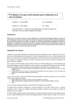
EEL 4924 Electrical Engineering Design
(Senior Design)
Final Design Report
19 April 2011
Project Name: uTouch
Team Members:
Name: Issam Bouter
Email: [email protected]
Phone: 561-685-7455
Name: Constantine Metropulos
Email: [email protected]
Phone: 561-251-2170
Project Abstract:
This project describes the functionality and building of a wireless touch pad universal controller
with a full color LCD. The point of this is to give the user visual feedback, simple device navigation and
to allow room functionality extensions. The functionality of the device includes several infrared
interfaces to be used as a universal remote control for several household entertainment devices, a GUI
with easy peripheral parameter settings, and the ability to use the device as a computer mouse, keyboard
and shortcut remote through Bluetooth.
University of Florida
EEL 4924—Spring 2011
20-Apr-11
Electrical & Computer Engineering
Page 2/13
Product Design Report: uTouch
Table of Contents
Product Features and Objectives ........................................................................................................ 3
Analysis of Competitive Products ..................................................................................................... 3
Concept and Technology Selection ................................................................................................... 4
Project Architecture ............................................................................................................................ 5
Division of Labor ................................................................................................................................ 7
User Manual ……................................................................................................................................ 8
Bill of Materials (BOM) .................................................................................................................... 13
Projected Timeline ............................................................................................................................. 13
List of Figures
Figure 1: Apple Wireless Multi-Touch Pad ....................................................................................... 3
Figure 2: Samsung Multifunction Touchscreen Learning Remote .................................................... 4
Figure 3: Apple iPhone 4 (32-GB Model) ......................................................................................... 4
Figure 4: uTouch Detailed Functional Block Diagram ...................................................................... 5
Figure 5: LCD Driver Software Flowchart ........................................................................................ 6
Figure 6: Python Windows Computer Program Flowchart ................................................................ 7
Figure 7: MSP430F2272 Software Flowchart ................................................................................... 7
Figure 8: Picture of uTouch Device (Front) …................................................................................... 9
Figure 9: Picture of uTouch Device (Back) ....................................................................................... 9
Figure 10: Gantt Chart of Timeline ...................................................................................................10
Figure 11: Gantt Chart of Timeline ...................................................................................................10
Figure 12: Gantt Chart of Timeline ...................................................................................................11
Figure 13: Gantt Chart of Timeline ...................................................................................................11
Figure 14: Gantt Chart of Timeline ...................................................................................................12
Figure 15: Gantt Chart of Timeline ...................................................................................................12
Figure 16: Gantt Chart of Timeline ...................................................................................................12
Figure 17: Gantt Chart of Timeline ...................................................................................................13
List of Tables
Table 1: Distribution of Labor ……………..……............................................................................. 6
Table 2: Bill of Materials (BOM) ……...…..……............................................................................. 8
University of Florida
EEL 4924—Spring 2011
20-Apr-11
Electrical & Computer Engineering
Page 3/13
Product Design Report: uTouch
Product Features and Objectives:
This project incorporates elements of both electrical and computer engineering and computer science
design. The application domain for this project spans the areas of wireless communication, universal
controllers, human interface technologies, microprocessor applications, and remote computer access and
control.
The main purpose of this project is to develop an efficient low-power wireless touch computer and
infrared device controller using an LCD screen and a touch pad. This means that power consumption is
important and was a key design limitation. The microprocessor selected needed to run at high enough
speeds to communicate with multiple peripherals. For its exceptionally low power consumption and
debugging flexibility, the MSP430F2272 was chosen. Size is also an important consideration, as this
device is intended to be portable. Careful consideration was placed on final product size during the
design, implementation, and construction of the system. The final uTouch device module measures
approximately 4.25”x3.75”x1.25”, which is well under our aim of the largest size being 10”x7”x2”.
With the Lithium Polymer batteries currently used, we are able to achieve a operation time of about 2
hours, which is about half of our initial desired time of four hours but with an upgrade from two
1000maH batteries to 2000maH batteries the operation time can approximately double.
Analysis of Competitive Products:
Currently the only comparable products in the commercial market are the Apple wireless multi-touch
pad priced at $69.00 (shown in Figure 1 below), the Samsung Multifunction Touchscreen Learning
Remote priced at $299.99 (shown in Figure 2 below), and the Apple iPhone 4 32GB model priced at
$299.00 (shown in Figure 3 shown below). However, our product will differentiate itself from the all of
these products by bridging the gap between them by controlling both infrared and Bluetooth devices. We
hope to develop a GUI interface that will allow simple user interface with parameter setting and visual
feedback. Even though the uTouch controller has the functionality of multiple commercially available
products, it could be sold at an outstanding price of about $200.
Figure 1: Apple Wireless Multi-Touch Pad
University of Florida
EEL 4924—Spring 2011
20-Apr-11
Electrical & Computer Engineering
Page 4/13
Product Design Report: uTouch
Figure 2: Samsung Multifunction
Touchscreen Learning Remote
Figure 3: Apple iPhone 4 32GB model
Concept and Technology Selection:
The main objective of our project was to build a complete intelligent remote control that could be used
to control any Infrared device by learning infrared codes, and then transmitting the commands using a
high-output infrared light emitting diode. Our main objectives were size, portability, usability, and low
power consumption. We designed uTouch with these aspects in mind; carefully selecting appropriate
parts that would lead to a complete final product. A 16-bit full-color touchscreen LCD was chosen for its
compactness, moderate power usage, and versatility. This full-color touchscreen LCD allows uTouch to
be presented to a user in an intuitive and easy to use manner. Since size, portability, and power were also
main concerns, a large part of the design went into battery management. We chose to use two 1000mAh
rated 3.7V Lithium Polymer batteries in series to meet our need for a power supply voltage over 5V. The
voltage was designed to be a few volts over the needed 5V so that it could be regulated to a steady
voltage and to lessen the impact of the battery discharge. This 2-cell Lithium Polymer battery pack is
charged using a 2-Cell Lithium Polymer Battery Charging Integrated Circuit from Texas Instruments
(BQ2057). The charging circuit functions in such a way as to charge the battery pack at a constant
voltage with a temperature regulated trickle down current. The main concept is that the voltage across
the battery pack stays the same, while the current is slowly decreased as the battery charges. An LED
indicates the status of the charger, which automatically turns off when charging is complete. Another
concern for building such a small compact unit was temperature, to take care of this aspect we
incorporated a thermistor into the charging circuit to monitor the battery pack temperature and to
suspend charging when higher temperatures are reached. The focal point of our IR learning and
transmission was accomplished using an MSP430F2272. This chip was chosen for its built in modules
and exceptionally low power consumption. A major obstacle was determining how to learn, permanently
save, and then transmit an IR code. Learning the IR code was accomplished using a phototransistor and
a custom built low pass amplifier circuit, and reading that output to the microprocessor through an
Analog to Digital Convertor (ADC). An external SD Card was interfaced into the device in order to save
a large number of IR codes while the device is functioning retain them when the device is not powered.
In order to accomplish the storing and reading from an SD card, the SD protocol had to be studied and
implemented. Once the IR code is read back into the MSP temporary storage, it is modulated and sent
back out at between 38kHz and 40kHz (the standard is 38kHz, and nearly 85% of all IR devices use this
range of modulation frequency). The LCD screen loads images from a micro SD card. Each image has
regions of detection hardcoded in the LCD’s flash. The driver for the system is a PICASO-GFX2
processor that is coded in 4dgl, a proprietary programming language. The logic of the LCD screen is
University of Florida
EEL 4924—Spring 2011
20-Apr-11
Electrical & Computer Engineering
Page 5/13
Product Design Report: uTouch
state machine based. Each image is loaded and regions in the touchscreen cause different screens to be
loaded or spi commands to be sent out. Some on the go graphics rendering happens for the mouse state,
which gives the user some visual feedback. The LCD spi lines are connected to the Bluetooth device as
well as the msp430. There is an identifier for each command that both the msp430 and the computer
have to decipher and react accordingly. The baud rate of the Bluetooth is 115200 so each transmission to
the computer happens very quickly.
Project Architecture:
The system level architectural block diagram in Figure 4 displays the overall connections and
architecture of our system. The LCD driver PICASO-GFX2 controls the 16-bit full-color LCD screen to
display the uTouch interface to the user. The flowcharts for the architecture and operation of this
interface can be found in Figures 5. This figure shows the LCD driver chip software flowchart. The
graphical displays that are presented to the user can be found in the User Manual section of the paper.
The driver chip then processes the users commands via the resistive touchpad. From there, the driver
chip will either control the Bluetooth module to communicate with the Python windows program, it will
also send commands to the MSP430 F2272 microcontroller. The flowchart for the Python windows
computer program can be found in Figure 6. The Python program consists of a Bluetooth driver, which
interprets received commands into mouse, keyboard, and shortcut actions, alongside a GUI process
which serializes user input to the hard drive and communicates it to the Bluetooth process through a cue.
The MSP430 will then control the Infrared (IR) input and output, depending on the command received
from the PICASO-GFX2 processor. The MSP continuously runs a main loop to check for flags set.
When the learning flag is set, the MSP reads the IR input through an ADC channel from a custom
designed low pass amplifier circuit using a phototransistor. The start of the IR code is found, and the
following code is saved to ram in the MSP. The MSP then recognizes that there is a code waiting to be
saved to the SD Card, and proceeds to save the code permanently on the external SD Card. Once the IR
code has been saved to the memory card, the focus returns to the LCD driver, which will repeat its
functionality previously described, or can also send the MSP a transmit command. When this transmit
command is received, the MSP will read the IR code off of the external SD Card into onboard temporary
memory, and will transmit the IR code through a high power IR LED. The flowchart of the MSP
program functionality can be seen in Figure 7.
University of Florida
EEL 4924—Spring 2011
Electrical & Computer Engineering
Page 6/13
Product Design Report: uTouch
Figure 4: uTouch Detailed System Block Diagram
Figure 5: LCD Driver Chip Software Flowchart
20-Apr-11
University of Florida
EEL 4924—Spring 2011
Electrical & Computer Engineering
Page 7/13
Product Design Report: uTouch
Figure 6: Python Windows Computer Program Flowchart
Figure 7: MSP430F2272 Software Flowchart
20-Apr-11
University of Florida
EEL 4924—Spring 2011
20-Apr-11
Electrical & Computer Engineering
Page 8/13
Product Design Report: uTouch
Division of Labor:
The following is a breakdown of each team member's projected labor by approximate percentage.
Issam Bouter
Constantine Metropulos
Preliminary Research
50
50
Obtain Materials and Parts
50
50
Project Component Design
50
50
Color LCD & Touchpad System
90
10
Bluetooth Module
80
20
Computer Bluetooth Drivers & Software
80
20
Infrared Learning & Transmitting
20
80
Various Input Buttons & Devices
50
50
Battery Charging
20
80
System Integration
50
50
PCB Design & Construction
50
50
Test & Debug
50
50
Table 1: Distribution of Labor
User Manual:
The uTouch Universal Learning Remote Control is incased in a clear plastic case to allow the user to
enjoy the technical aspect of the design. The clear case also allows for the secure placement of LEDs on
the inside of the case, while still being visible from the outside. Pictures of the front of the uTouch
controller, the side with the full-color LCD (Figure 8), and the back of device (Figure 9) give a general
idea of the size and look of the device. The screen shown in Figure 8 is the Main Menu screen of the
LCD controller that allows the user to choose which feature they would like to use.
University of Florida
EEL 4924—Spring 2011
20-Apr-11
Electrical & Computer Engineering
Page 9/13
Product Design Report: uTouch
Figure 8: Picture of uTouch Device (Front)
Figure 9: Picture of uTouch Device (Back)
The flow of the LCD software is described above in Figure 5, this flow determines which menu is
displayed on the LCD screen for the user. The following figures are the completely list of menus
available to the user.
University of Florida
EEL 4924—Spring 2011
Electrical & Computer Engineering
Page 10/13
Product Design Report: uTouch
Figure 10: TV Infrared controller screen. Each button can be programmed to learn an infrared code.
Figure 11: Help screen. Describes the functionality of sections for the mouse interface state.
20-Apr-11
University of Florida
EEL 4924—Spring 2011
20-Apr-11
Electrical & Computer Engineering
Page 11/13
Product Design Report: uTouch
Figure 12: Number Pad Infrared controller screen. Each button can be programmed to learn an infrared code.
Figure 13: Mouse interface state. Changes of touch on this screen are sent to Bluetooth as a mouse change command. This
has a menu button for personalizing this state, help button, shortcut buttons and the keyboard changes the state to the
keyboard interface state.
University of Florida
EEL 4924—Spring 2011
Electrical & Computer Engineering
Page 12/13
Product Design Report: uTouch
Figure 14: Computer Infrared controller screen. Each button can be programmed to learn an infrared code.
Figure 15: VCR Infrared controller screen. Each button can be programmed to learn an infrared code.
Figure 16: DVD Infrared controller screen. Each button can be programmed to learn an infrared code.
20-Apr-11
University of Florida
EEL 4924—Spring 2011
20-Apr-11
Electrical & Computer Engineering
Page 13/13
Product Design Report: uTouch
Bill of Materials (BOM):
2x Advanced Circuits PCB
2x RN-41 Bluetooth
2x TFT 3.2” LCD
Various Capacitors and Resistors
741 Op Amp
IR LED and phototransistor
Enclosure
SD Card and Housing
Micro SD card
TI BQ2057 Charging IC
Misc. connectors, plugs and wires
LED’s
$66
$100
$180
$10
$1
$5
$11
$50
$35
Free Sample
$30
$3
Gantt Chart / Project Schedule:
The following figure (Figure 10) displays the project timeline for the completion of the project in the
form of a Gantt Chart.
Figure 17: Gantt Chart of Projected Timeline