1
University of Florida
Department of Electrical and Computer Engineering
Page 1/11
EEL 4744
Revision 0
Dr. Eric M. Schwartz
Josh Weaver, PhD Candidate
12-Feb-14
Mixed C and Assembly Atmel XMEGA
KEY WORDS
Compiler, Inline Assembly, GNU Assembler, GCC, AVR-GCC
RESOURCES
GNU Assembler Resource - http://sourceware.org/binutils/docs-2.23.1/as/index.html
AVR-LibC Inline ASM Cookbook - http://www.nongnu.org/avr-libc/user-manual/inline_asm.html
Atmel APPNote AT1886 - http://www.atmel.com/images/doc42055.pdf
Atmel APPNote AVR1000 - http://www.atmel.com/Images/doc8075.pdf
INTRODUCTION
Beyond standard assembly programming for a specific device, some devices allow the use of the C programming language to
create code that will control the device. When a computer program is completed in a source language such as C, it must then
be converted to a target language to control the desired device. To do this, a compiler is used to transform the source code
into the desired object code (e.g., assembly language).
During the conversion process, the compiler attempts to “optimize” the order and use of object code. Given that a compiler
tries to be quick, or simply may be poorly built, it is possible that the resulting object code may not be as fast or efficient as
desired. A programmer who is familiar with assembly may want to take advantage of their skills to improve the resulting
assembly code given by using assembly within the C program being generated. Specifically, a programmer may desired for a
C program to call an Assembly function or vice versa. For Atmel, this happens in either two cases: the use of “.s” assembly
files, or using “inline assembly” commands.
Note that for Atmel, the GCC (AVR-GCC) compiler is used to combine .c, .cpp, or .s files to create a project.
C ASSEMBLER
When creating a C project, if working with long and complex pieces of assembly code is required, it is more desirable to
express the code in a dedicated assembler file. The portions of C code and Assembly code can be used to communicate
between each other so nothing is lost, allowing that the programmer pays close attention to the use of registers. Typically,
Assembler files are very useful in cases of optimizing large pieces of code such as communication with external devices or
Interrupt Service Routines.
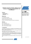
// Program Flash Data Section (in Code Memory Space)
.section .text
VA: .byte 1,2,3,4,5,6
VB: .byte 0xA0, 0xB0, 0xC0, 0xD0, 0xE0, 0xF0
.section .text
/*******************************PRIMARY CODE****************************************/
.global MAIN_ASM // The assembly function must be declared as global
MAIN_ASM:
ldi R18, N
ldi ZL, lo8(VA)
ldi ZH, hi8(VA)
// Load the number of values
// Load the address of program memory for VA
call VADD
ret
// Call the ASM function for vector addition
// Return to call from C code
Figure 1: Assembler File .s example
INLINE ASSEMBLY
In cases where smaller pieces of assembly code are used, inline assembly commands directly embedded into the C code may
be desirable. In these cases, instead of creating a separate Assembler file, the “asm” command may be used to wrap around
and insert assembler commands into C.
University of Florida
Department of Electrical and Computer Engineering
Page 2/11
EEL 4744
Dr. Eric M. Schwartz
Josh Weaver, PhD Candidate
12-Feb-14
Revision 0
Mixed C and Assembly Atmel XMEGA
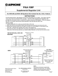
// Program Flash Data Section (in Code Memory Space)
asm(".section .text");
asm("VA: .byte 1,2,3,4,5,6");
asm("VB: .byte 0xA0, 0xB0, 0xC0, 0xD0, 0xE0, 0xF0");
/*******************************PRIMARY CODE****************************************/
void VADD();
// C Prototype for VADD
// Main function required in primary C file of project
int main(void)
{
asm("ldi R18, N");
// Load the number of values
asm("ldi R30, lo8(VA)");
// Load the address of program memory for VA
asm("ldi R31, hi8(VA)");
asm("ldi R26, lo8(VC)");
// Load the address of data memory storage for
VC result
asm("ldi R27, hi8(VC)");
VADD();
// Use C function call
// DONE while loop once main program is complete
while(1)
{
}
}
Figure 2: Inline Assembly example
C ASSEMBLER (.S) USAGE
REGISTERS
When using the GCC compiler in a C program, registers are used slightly differently from a standard assembly project. First,
r0 is defined as a temporary register which may be used by compiler generated code. Any assembly code that uses r0 and
calls a C function should save and restore the register. r1 is assumed to always be zero by the compiler, so any assembly
code that uses this should clear the register before calling compiler generated code. The rest of the registers are defined as
being “call-saved” or “call-used”. “call-saved” registers are those that a called C function may leave unaltered, however,
assembly functions called from C should save and restore the contents of the register (using the stack). “call-used” registers
are available for any code to use, but if calling a C function, these registers should be saved since compiler generated code
will not attempt to save them.
A table is give below to quickly define how each register is to be considered:
Table 1: Register Interfaces between C and Assembly
Register
r0
r1
r2-r17
r28
r29
r18-r27
r30
r31
Description
Temporary
Always Zero
Assembly code called from C
Save and restore if using
Must clear before returning
Assembly code that calls C code
Save and restore if using
Must clear before returning
“call-saved”
Save and restore if using
Can freely use
“call-used”
Can freely use
Save and restore if using
University of Florida
Department of Electrical and Computer Engineering
Page 3/11
EEL 4744
Revision 0
Dr. Eric M. Schwartz
Josh Weaver, PhD Candidate
12-Feb-14
Mixed C and Assembly Atmel XMEGA
COMMANDS AND CONSTRAINTS
All commands that are given through the instruction set are available in the mixed C/Assembly setup. Below is a subset of
the instruction set, but are many of the primary commands that are given in various avr-gcc compiling guides. Notice the
constraint descriptions are slightly different.
Table 2: Commands in AVR-GCC
Mnemonic
adc
add
adiw
and
andi
asr
bclr
bld
brbc
brbs
bset
bst
cbi
cbr
com
cp
cpc
cpi
cpse
dec
elpm
eor
in
inc
ld
ld
ld
ldd
ldi
lds
lpm
lsl
lsr
mov
movw
mul
muls
neg
or
ori
out
pop
push
rol
Constraint
r, r
r, r
w, I
r, r
d, M
r
I
r, I
I, label
I, label
I
r, I
I, I
d, I
r
r, r
r, r
d, M
r, r
r
t, z
r, r
r, I
r
r, e
r, e+
r, -e
r, b + I
d, M
r, label
t, z
r
r
r, r
r, r
r, r
d, d
r
r, r
d, M
I, r
r
r
r
Meaning
Add without Carry
Add with Carry
Add Immediate to Word
Logical AND
Logical AND with Immediate
Arithmetic Shift Right
Flag Clear
Bit load from T to Register
Branch if Status Flag Cleared
Branch if Status Flag Set
Flag Set
Bit Store from Register to T
Clear Bit(s) in I/O Register
Clear Bit(s) in Register
One’s Complement
Compare
Compare with Carry
Compare with Immediate
Compare, Skip if Equal
Decrement
Extended Load Program Memory
Exclusive OR
In From I/O Location
Increment
Load Indirect
Load Indirect, post-increment
Load Indirect, pre-decrement
Load Indirect with Displacement
Load Immediate
Load Direct from data space
Load Program Memory
Logical Shift Left
Logical Shift Right
Copy Register
Copy Register Pair
Multiply Unsigned
Multiply Signed
Two’s Compliment
Logical OR
Logical OR with Immediate
Out To I/O Location
Pop Register from Stack
Push Register on Stack
Rotate Left Through Carry
University of Florida
Department of Electrical and Computer Engineering
Page 4/11
EEL 4744
Dr. Eric M. Schwartz
Josh Weaver, PhD Candidate
12-Feb-14
Revision 0
Mixed C and Assembly Atmel XMEGA
Mnemonic
ror
sbc
sbci
sbi
sbic
sbiw
sbr
sbrc
sbrs
ser
st
st
st
std
sts
sub
subi
swap
xch
Constraint
r
r, r
d, M
I, I
I, I
w, I
d, M
r, I
r, I
d
e, r
e+, r
-e, r
b, r
label, r
r, r
d, M
r
z, r
Meaning
Rotate Right Through Carry
Subtract with Carry
Subtract immediate with Carry
Set Bit in I/O Register
Skip if Bit in I/O Register Cleared
Subtract Immediate from Word
Set Bit(s) in Register
Skip if Bit in Register Cleared
Skip if Bit in Register Set
Set Register
Store Indirect
Store Indirect, Post-Increment
Store Indirect, Pre-Increment
Store Indirect with Displacement
Store Direct to Data Space
Subtract without Carry
Subtract Immediate
Swap Nibbles
Exchange
Though the commands are like standard assembly commands, some of the constraints are described slightly differently. For
instance, some commands that you could typically use register definitions such as XH or XL must now use their specific
register declarations (r27 or r26). A description of the various constraints as well as operand definitions seen in other C
Assembly structures is shown in Table 3.
Table 3: Command/Operand Constraints
Constraint
a
b
d
i
l
m
n
q
r
s
t
w
x
y
z
G
I
J
M
0…9
Type
Simple upper register
Pointer Register
Upper Register
Constant
Lower Register
Memory
Value is known at compile
Stack Pointer
Any Register
Pointer Register
Scratch (Temp) Register
Upper Register pairs
Pointer Register x
Pointer Register y
Pointer Register z
Floating-point Constant
6-bit positive constant
6-bit negative constant
8-bit integer constant
Identical to the specified operand
Range of Values
r16 … r23
y, z
r16 … r31
r0 … r15
SPH: SPL
r0 to r31
x, y, z
r0
r24, r26, r28, r30
x ( r27: r26)
y ( r29: r28)
z ( r31: r30)
0.0
0 to 63
- 63 to 0
0 to 255
Notice that the X register is r27:r26, y register is r29:r28, and z register is r31:r30.
University of Florida
Department of Electrical and Computer Engineering
Page 5/11
EEL 4744
Revision 0
Dr. Eric M. Schwartz
Josh Weaver, PhD Candidate
12-Feb-14
Mixed C and Assembly Atmel XMEGA
SYNTAX
When working with Assembler files within C, there are small changes from what is expected in an assembly file.
In code segments, .org is not needed since the compiler handles code placement.
In data segments, .org directives are offset from the last location used by the compiler in placement.
The .s extension is used for assembler files.
Lines using preprocessor directives defined by # must use C/C++ style comments (semicolons will cause errors)
Table 3 shows a comparison of the structures for assembly and C.
Table 4: Structure Comparisons
Atmel AVR
.include “xxx.inc”
.dseg
.cseg
.db 1,2,3,4
.db “message”
.db “message”, 0x00
.dw
HIGH()
LOW()
AVR-GCC
#include <avr.io>
.section .data
.section .text
.byte 1,2,3,4
.ascii “message”
.asciz “message”
.word
hi8()
lo8()
EXAMPLES
.DSEG AND DATA MEMORY
When working with data memory the “.section .data” structure is used. The below example shows various methods of using
Data Memory:
// SRAM Data Segment
.section .data
// This will start at address 0x2000 as default
Text: .asciz
"hello world"
Variable1:
Variable2:
Variable3:
.ds.b 4
.ds.w 2
.byte 5
// Define storage of bytes 4 long
// Define storage of words 2 long
// Define byte value of 5
.global __do_copy_data // Copy a defined variable in program memory to data memory
Figure 3: .DSEG and Data Memory example
The Text label uses “asciz” to define a null terminated string. Labels Variable1 and Variable2 are used to define storage
spaces of either byte size or words size respectively. Label Variable3 is used to define a specific value of 5 in a space of byte
size.
Data memory is typically used for creating storage of variables such as defined by Variable1 and Variable2. In some cases,
it is desired to not only create a space in memory, but also to define a value to be stored at that position on startup. Text and
Variable3 define a space in data memory as well as desired initial values. The initial value is initially stored in program
memory, however, the special command .global __do_copy_data handles copying the data from program memory to the
desired position for that information in data memory.
.CSEG AND PROGRAM MEMORY
Like assembly, program memory is used to hold both program variables (constants) and the assembly code. The following
example shows how the “.section .text” structure may be used:
University of Florida
Department of Electrical and Computer Engineering
Page 6/11
EEL 4744
Revision 0
Dr. Eric M. Schwartz
Josh Weaver, PhD Candidate
12-Feb-14
Mixed C and Assembly Atmel XMEGA
// Program Flash Data Section (in Code Memory Space)
.section .text
Variable1: .byte 1,2,3,4,5,6
Variable2: .byte 0xA0, 0xB0, 0xC0, 0xD0, 0xE0, 0xF0
/*******************************PRIMARY CODE****************************************/
.global MAIN_ASM // The assembly function must be declared as global
MAIN_ASM:
ldi R18, N
ldi ZL, lo8(VA)
ldi ZH, hi8(VA)
// Load the number of values
// Load the address of program memory for Variable1
call VADD
ret
// Call the ASM function for vector addition
// Return to call from C code
Figure 4: .CSEG and Program Memory example
The Variable1 and Variable2 labels define a place in program memory that holds two sets of respective values. Following
this declaration, the main body of the assembly program (various functions) may now be defined.
ASSEMBLY FUNCTION DEFINITIONS AND USE
Assembly functions are defined the same way they are in a standard assembly project using standard labels. The “ret”
command is still used to return from a function call to an assembly function. Within the Assembler file (.s), calls between
functions within the same file require no special consideration. However, when dealing with calls to assembler functions
from C code, the function must be define a special way.
/*********************************INITIALIZATIONS***********************************/
extern void MAIN_ASM(); // C Prototype that defines an externally defined function
// Main function required in primary C file of project
int main(void)
{
MAIN_ASM();
// Single call to Vector Add Function
}
Figure 5: Assembly Function Use - .c File
/*******************************PRIMARY CODE****************************************/
.global MAIN_ASM // The assembly function must be declared as global
MAIN_ASM:
ret
// Return to call from C code
Figure 6: Assembly Function Use - .s File
The above two examples show both the .c file and the .s file descriptions for connection to an assembly function. In the .c
file, a C Prototype is created for the assembly function. The use of the “extern” keyword shows that the function is externally
defined. The assembly function is later called in the .c file. In the .s file, the assembly function is defined by the “.global”
directive to make the function available to other partial programs that are linked within the project. Notice that within the
assembly function the “ret” command is still used to return from the function when it is complete.
INLINE ASSEMBLY USAGE
Many of the rules and usage defined within the C Assembler section are used when executing inline assembly commands.
The following sections will detail the differences in Syntax usage as well as define the templates used when working with
inline assembly.
University of Florida
Department of Electrical and Computer Engineering
Page 7/11
EEL 4744
Revision 0
Dr. Eric M. Schwartz
Josh Weaver, PhD Candidate
12-Feb-14
Mixed C and Assembly Atmel XMEGA
SYNTAX
As described, inline assembly makes use of the asm() command (also defined as __asm or __asm__). In special
circumstances where it is important that the command should not be optimized away (i.e., not moved from the defined
position in memory), the volatile modifier should be added (asm volatile ()). Notice that the volatile modifier does not need
to be used at every asm call. The template for the asm call follows:
asm volatile ( asm-template
: output-operand-list
: list-input-operand
: clobber list )
The asm-template follows the standard assembly instruction structure defined in Table 2: Commands in AVR-GCC. The
assembly instructions are incased in quotes. The asm-template may use “%” expressions to define placeholders replaced by
operands defined in the output-operand-list and list-input-operand sections. Below is a table of possible placeholders:
Table 5: ASM Template Placeholders
Placeholder
%n
A% n
%Bn
%Cn
%Dn
%An
%%
\\
\N
\T
Replaced by
By argument in operands where n = 0 to 9 for argument
The first register of the argument n (bits 0 to 7)
The second register of the argument n (bits 8 to 15)
The third register of the argument n (bits 16 to 23)
The fourth register of the argument n (bits 24 to 31)
The Address register X, Y, or Z
The % symbol when needed
The \ symbol when needed
A newline to separate multiple asm commands
A tab used in generated asm
The output-operand-list and list-input-operand follows the definitions given in Table 3: Command/Operand Constraints.
The various operands may be used with various modifiers as defined in the following:
Table 6: Operand Modifiers
Modifier
Meaning
=
Output operand
&
Not used as input but only an output
+
Input and Output Operand
Operands are used by placing an operand (and modifier) in quotes, while placing the true variable, register, or memory
position in parenthesis. Any C expression may be used within the parenthesis.
EXAMPLES
SIMPLE INLINE ASSEMBLY COMMANDS
When using simple inline assembly commands, there is little difference from the look in a C Assembler (.s) file other than the
required asm(“ “) function call surrounding the assembly command.
University of Florida
Department of Electrical and Computer Engineering
Page 8/11
EEL 4744
Revision 0
Dr. Eric M. Schwartz
Josh Weaver, PhD Candidate
12-Feb-14
Mixed C and Assembly Atmel XMEGA
void VADD()
{
asm("nop");
asm("VADD_ASM: push R18");// Push the number of values onto the stack for later use
asm("movw R28,R26");
// movw Y, X
asm("mov R19, R18");
// Copy count of values in vector to counter register
// Work with first vector
asm("LOOP:");
asm("lpm R21, Z+");
//
asm("st
Y+, R21");
//
asm("dec R19");
//
asm("brne LOOP");
//
asm("pop R19");
//
Load values of first vector pointed to by Z
Store currently loaded value into data memory pointed by Y
Decrement counter
Loop until counter = 0
Restore the count of values in vector to counter register
Figure 7: Simple Inline Assembly example
INLINE ASSEMBLY COMM ANDS USING OPERANDS
In circumstances where defined PORT names, Control Registers, or Memory locations are used, the more advanced asm()
template with operands must be used. In some of these situations, it is also important to insure that the assembly command
used is not moved during the compiler process, requiring the volatile modifier to be used.
asm("LDI R18, 0xFF");
asm volatile ("STS %0,r18" : "=m" (PORTK_DIRSET));
asm("LDI R18, 0x01");
asm volatile ("STS %0,r18" : "=m" (EBI_CTRL));
asm volatile("LDI R31, hi8(%0)" :: "i" (&EBI_CS0_BASEADDR));
asm volatile("LDI R30, lo8(%0)" :: "i" (&EBI_CS0_BASEADDR));
asm("LDI R18, (IOPORT>>8)");
asm("ST Z+, R18");
Figure 8: Inline Assembly with Operands example
In the example, the STS command used to define PORTK_DIRSET uses a simple placeholder operand (%0) showing that
the defined operand will come later in the template. Then, in the output operand section, PORTK_DIRSET is defined as an
output only memory (“=m”) location address.
Later in the example, the LDI command used to define EBI_CS0_BASEADDR uses another simple placeholder operand
(%0). The operand is later shown to be an input operand defined as a constant (“ i ”). The constant is defined by using the C
Pointer “&” modifier on EBI_CS0_BASEADDR.
The “&” designated for C to return the address of
EBI_CS0_BASEADDR.
University of Florida
Department of Electrical and Computer Engineering
Page 9/11
EEL 4744
Revision 0
Dr. Eric M. Schwartz
Josh Weaver, PhD Candidate
12-Feb-14
Mixed C and Assembly Atmel XMEGA
STARTING A C PROJECT
To begin, a C Project must be first started within Atmel Studio. After opening Atmel Studio, choose New Project and make
sure to choose the “GCC C Executable Project” option.
Once the project is open, the standard “.c” file will be opened with the template “main” function. C code may be written
using the “main” function as the starting point. Assembly may be used in a new “.s” file added to the project or directly
inserted using inline assembly commands within the “.c” file.
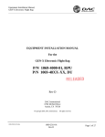
TO CREATE “.S” ASSEMBLY FILE
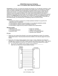
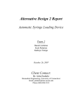
All files for the project are displayed in the Solution Explorer. Right click on the project name in the Solution Explorer
(highlighted in figure) and choose “Add -> New Item” in context menu. In the new “Add New Item” window, choose to
create an Assembly File. This new file will then be displayed in the Solution Explorer.
University of Florida
Department of Electrical and Computer Engineering
Page 10/11
EEL 4744
Revision 0
Dr. Eric M. Schwartz
Josh Weaver, PhD Candidate
12-Feb-14
Mixed C and Assembly Atmel XMEGA
Figure 9: Project Solution Explorer Window
Figure 10: Add New Item Window
University of Florida
Department of Electrical and Computer Engineering
Page 11/11
EEL 4744
Revision 0
Dr. Eric M. Schwartz
Josh Weaver, PhD Candidate
12-Feb-14
Mixed C and Assembly Atmel XMEGA
TROUBLESHOOTING
GARBAGE AT END OF LI NE
If you receive an error with the following comments
;’ required
constant value required
garbage at end of line
Check any lines with preprocessor directives that begin with # (e.g., #include, #define). If comments follow the directive,
they must be in the form of C/C++ style comments. Any comments using assembler structure with a semicolon will result in
an error.
DEFINING A VARIABLE WITH INLINE ASM DOES NOT WORK
Using the standard method of a #define will not connect correctly when used within an asm command:
asm(“#define test r18”)
To define the register correctly you can use the command:
register unsigned char CTR asm("r18");
Notice you will get a warning “call-clobbered register used for global register variable [enabled by default]” depending on
the register you use.