1
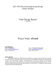
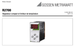
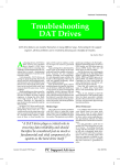
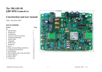
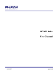
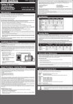
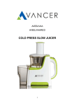
Remote Controlled Fetch
Machine
Final Design Report with Diagrams
EEL4924 – Senior Design
19 April 2011
Members: James Su & Brandon Grillo
Project Abstract:
The Remote Controlled Fetch Machine is a device designed to reinvent the
way owners can exercise and entertain their dogs. It allows owners to play a game
of fetch with their dog from a distance with the use of a handheld remote featuring
an intuitive interface.
The handheld remote features an LCD screen and buttons to navigate an onscreen menu. These buttons are used to control the behavior of the machine. Also,
the remote has an accelerometer, which allows users to swivel the machine by
tilting the remote left, right, or toward the user.
University of Florida
EEL4924 – Senior Design Spring 2011
2
Remote Controlled Fetch Machine
Table of Contents
Project Features
Competitive Products
Implementation
Project Architecture
Project Responsibilities
User Manual
Bill of Materials
Gantt Chart
Appendix
pg. 3
pg. 4
pg. 5
pg. 7
pg. 12
pg. 12
pg. 13
pg. 14
pg. 15
List of Tables and Figures
Fig. 1: Diagram of swivel and launch capabilities
Fig. 2: Picture of competitive product
Fig. 3: Machine design
Fig. 4: Machine block diagram
Fig. 5: Speed controller circuit diagram
Fig. 6: Force sensor circuit diagram
Fig. 7: Remote block diagram
Fig. 8: Machine software flow chart
Fig. 9: Remote software flow chart
Fig. 10: Gantt chart
pg. 3
pg. 4
pg. 5
pg. 7
pg. 8
pg. 9
pg. 9
pg. 10
pg. 11
pg. 14
Table 1: Division of labor
Table 2: Bill of materials (costs)
pg. 12
pg. 13
University of Florida
EEL4924 – Senior Design Spring 2011
3
Remote Controlled Fetch Machine
Project Features:
The Remote Controlled Fetch Machine will be comprised of two major
components: a remote and a device that will throw a ball. The throwing machine
will have the following features:
•
•
•
•
•
•
•
•
•
•
•
Machine:
Ability to throw a miniature tennis ball.
The entire machine can swivel horizontally between 0° and 135°.
The ball can be thrown at an angle from 0° to 35°from the horizontal.
Sensor to detect the presence of a ball in the machine.
“Automatic and Manual Modes” that automatically throws a ball when it is
retrieved without the user’s command, or throws a ball on command.
“Indoor and Outdoor Modes” that changes the distance that the ball is thrown
by adjusting motor speed.
Large drop zone for retrieved tennis balls to be placed.
Remote:
Accelerometer for tilt sensing control.
A basic LCD Screen for a simple menu interface.
Interface buttons to select modes and menu items.
Both the machine and remote will include a transceiver to allow for RF
communication
The final design for the machine met and exceeded all of our initial design
objectives. Several features we have added which were not part of the original basic
design include the ability to launch the ball at different speeds, the ability to have
varying launch angles, and the possibility of having a color LCD screen.
Figure 1: Diagram showing horizontal swivel capability on the machine (Left)
and diagram showing launch mechanism along with adjustable launch angle (Right).
University of Florida
EEL4924 – Senior Design Spring 2011
4
Remote Controlled Fetch Machine
Competing Products:
Commercial automatic fetch machines already exist. Two such products are the
GoDogGo® G3 Fetch Machine and the Fetchtastic Automatic Fetch Machine for Dogs.
These products are similar in that they both accomplish the following:
•
•
Throw a tennis ball up to 25-30 feet
Automatically throw a ball if there is one present
However these machines lack some key features of the Remote Controlled Fetch
Machine:
•
•
•
•
Swivel position left and right
Swivel trajectory up and down
Distance control
Wireless remote control
Figure 2: Example of a competitive product (Fetchtastic).
University of Florida
EEL4924 – Senior Design Spring 2011
5
Remote Controlled Fetch Machine
Implementation:
Implementation began by selecting microprocessors for the remote and
machine. The MSP430F2272 was chosen for two reasons. Its low power
consumption made it a perfect fit for a handheld remote. Also, its PWM capabilities
were robust and easy to configure for the machine’s needs.
The Machine:
The main design focus of the machine was choosing the method in which the
tennis balls would be thrown. The two primary choices for implementing this were:
• An arm that could launch the ball (similar to a catapult)
• The ball is fed between two wheels spinning in opposite directions (similar
to a baseball pitching machine)
Ultimately, we chose the second method because it required less mechanical
design and would be capable of throwing the ball farther.
Our next major concern with the machine was how to construct it. Although
plastic or metal would make the machine more durable, we chose to construct it out
of wood. We chose wood because metal and plastic are very expensive and difficultto-use construction materials without the proper tools. Using wood allowed us to
easily construct and modify the machine design.
Finally, we chose the electrical components that allowed us to achieve the
machine’s features. All movement features of the machine could be accomplished
with servos with appropriate torque for the feature it was implementing. A hightorque servo was installed on the bottom of the machine that would swivel it
clockwise and counterclockwise. A medium-torque servo was used to control the
elevation of the ramp. A small micro servo was used to control the latch that
released the balls into the throwing mechanism. Lastly, two 7.2V brushed DC
motors were used with a one-direction speed controller to implement the throwing
mechanism.
Figure 3: Picture showing machine design.
University of Florida
EEL4924 – Senior Design Spring 2011
6
Remote Controlled Fetch Machine
The Remote:
For the remote, the goal was to make the interface as simple and intuitive as
possible. We discussed various user-interface methods and eventually narrowed it
down to either a glove-based control or a normal handheld remote control. With
the glove control we were going to implement various types of sensors including
flex sensors, touch sensors, and various types of buttons while with the handheld
remote we were only going to use momentary push buttons. Ultimately, we
decided to go with the handheld remote design because it was simple, effective, and
cost efficient.
In order to implement swivel control in the machine, we decided to use a
simple 3-axis analog accelerometer for tilt-sensing in the remote. By using an
analog accelerometer, we were able to use two of the eight analog-to-digital
conversion pins on the MSP430 rather than take up one of the two USCI modules;
this provides flexibility when connecting additional peripherals. In addition, we
had an analog accelerometer available so this helped us cut back on costs.
Next, we had to decide on a wireless communication interface between the
remote and the machine. After weighing various options, we decided to use xBee
wireless transceivers because they had a suitable range, sufficient data transfer rate,
and an intuitive setup. One of the additional considerations for the project initially
was to possibly include a camera of sorts on the machine that was capable of
transmitting video data back to the remote. This would have required the use of a
faster wireless system since the xBee data transmission rate would not have been
sufficient. In the end, we decided to use the xBee modules and planned on switching
to another faster wireless system if we had time to implement video transmission.
Having decided on our wireless system, we then discussed display options.
For our purposes, a 16x2 monochrome LCD display was enough to present the
menu options and data sufficiently and was cost efficient as well. However we
decided to leave room for a possible upgrade to a 128x128 color LCD display, time
permitting.
For the remote casing we debated between building one out of wood and
ordering a premade plastic or aluminum one online. Because we had wood left over
from the machine construction, we decided to go with crafting the remote casing out
of wood since it would save us some costs.
University of Florida
EEL4924 – Senior Design Spring 2011
7
Remote Controlled Fetch Machine
Project Architecture:
The Remote Controlled Fetch Machine can be broken down into two projects:
the wireless remote and the fetch machine.
The Machine
The architecture of the fetch machine is represented in the block diagram
below.
Figure 4: Machine block diagram.
Functionality begins by initializing Timer A and B of the MSP430 to use its Pulse
Width Modulation (PWM) capabilities. Each servo requires a PWM signal to
operate. The pulse period for all servos is 20ms. The duty cycle for all servos varies
between 600ms and 2400ms. Based on the duty cycle, the servo will rotate to a
position between 0° and 180°. The motor speed controller also requires a PWM
signal at the same frequency, but its duty cycle ranges from 0% to 100% of the pulse
period. Once Timers A and B were initialized, the duty cycles for their corresponding
servos were set for their initial positions:
• The servo that swivels L/R was centered
• The servo that swivels U/D was set to 0° (ramp flat)
• The latch servo was set to a closed position
• The speed controller was set to 0% speed
The speed controller was designed using two IRF510 MOSFETs with a 12V PWM
signal at the gates. When 12V is applied to the gates, current passes through the
University of Florida
EEL4924 – Senior Design Spring 2011
8
Remote Controlled Fetch Machine
MOSFETS from the battery through the motors. By modulating the PWM duty cycle
from 0% to 100%, the DC motor speed is varied from 0% to 100%. Two MOSFETS
were chosen to conduct the high current demands of the motors. Below is the speed
controller design.
Figure 5: Speed controller circuit diagram.
Once all initializations were made, the MSP430 waits for a single byte of data
from the remote via an Xbee RF chip. The data codes can be found in the Appendix.
The byte is decoded, and either a PWM signal is changed or a mode
(automatic/manual or indoor/outdoor) is changed.
If the user chooses to throw a ball, the machine enters a routine that changes the
PWM signal of the speed controller and latch at certain time intervals in order to
release the ball into the throwing mechanism. Once the ball is thrown, the latch
returns to its closed positions and the motors are powered down.
If automatic mode is selected, the MSP checks for a ball. A force sensor was used
to detect the presence of a ball. The force sensor is a variable resistance that
changes as force is applied. The following circuit outputs a voltage between 0 and
3.3V which connects to the MSP430 ADC (analog to digital converter) where RM =
1.5MΩ.
University of Florida
EEL4924 – Senior Design Spring 2011
9
Remote Controlled Fetch Machine
1 1.5Ω
Figure 6: Force sensor circuit diagram.
If the voltage reaches a threshold of 1.6V, then a ball is present. If a ball is
present, the machine enters the throwing routine and then checks for data from the
remote. This process is repeated until manual mode is selected.
The program flow chart detailing this process is shown on the following page.
The Remote
The block diagram below illustrates the fetch machine remote’s architecture:
xBee 1mW chip
antenna
Four momentary
push buttons
ADXL335 analog
accelerometer
MSP430f2272
16x2 monochrome
LCD display
Figure 7: Remote block diagram.
Once the machine is powered on, the LCD screen (I/O pins for monochrome,
SPI for color), analog accelerometer via the ADC on the MSP430, and xBee module
via the UART on the MSP430 are initialized. The software then polls the button
switches constantly to see if the user has pressed any of them. Once a button is
pressed, the MSP430 sends out the corresponding command code byte to the xBee
and updates the menu on the LCD screen.
If the swivel button is pressed, the MSP430 continuously reads in, converts to
digital, and modifies (through a linear equation) two values, one for the x axis and
one for the y axis. This value is then compared to a table of discrete value ranges.
Based on where each value falls, the corresponding code containing the x and y
positions of the accelerometer is sent out through the xBee. Continuous position
data transmission ends once swivel mode is turned off. The program flow chart
detailing this process is shown on page 11.
University of Florida
EEL4924 – Senior Design Spring 2011
10
Remote Controlled Fetch Machine
Figure 8: Machine software flow chart.
University of Florida
EEL4924 – Senior Design Spring 2011
11
Remote Controlled Fetch Machine
Figure 9: Remote software flow chart.
University of Florida
EEL4924 – Senior Design Spring 2011
12
Remote Controlled Fetch Machine
Project Responsibilities:
Component
Brandon
Grillo
James
Su
Fetch Machine Construction
60%
40%
Servos, Motors, Force
Sensor
Fetch Machine MSP Code
100%
0%
100%
0%
Remote Construction
40%
60%
Buttons, LCD,
Accelerometer
Remote MSP Code
0%
100%
0%
100%
XBee TX/RX
50%
50%
Speed Controller
50%
50%
Table 1: Division of labor.
Overall, the division of labor closely followed the assigned responsibility table.
User Manual:
1) Turn on POWER for the machine as well as the remote via the power switch.
2) Pressing the MODE button will select MANUAL or AUTOMATIC mode.
a. MANUAL allows user control of the machine.
b. AUTOMATIC launches balls at regular intervals until turned off.
3) Pressing the DISTANCE button will select INDOOR or OUTDOOR.
a. INDOOR selection sets launch distance to approximately 15-20 feet.
b. OUTDOOR selection sets launch distance to approximately 30-40 feet.
4) Pressing the SWIVEL button will allow for manual aiming of the machine.
a. Tilting the remote horizontally or vertically will swivel the machine or
adjust the launch angle respectively.
b. SWIVEL stays on until the button is pressed again.
5) Pressing the THROW button while in ‘manual’ mode will launch a ball.
University of Florida
EEL4924 – Senior Design Spring 2011
13
Remote Controlled Fetch Machine
Bill of Materials:
Component
Price
Wood
$25
Wheels
$13
Xbee RF chip
$22.95 x 2 =
$45.90
Glue, Epoxy
$10
Servos
Motors
$11.99 +
$35.99 =
$47.98
$23.99 x 2 =
$47.98
Force Sensor
$7.95
MOSFETs
$1.95 x 2 =
$3.90
Battery
$17.99
Charger
$11.49
12V Power
Supply
$18.99
Tennis Balls
$6.98
Color LCD
$34.95
Accelerometer
$24.95
Buttons
$4.95
Machine PCB
$66
Remote PCB
$66
TOTAL COST
$$$
$454.01
Table 2: Table of total costs.
University of Florida
EEL4924 – Senior Design Spring 2011
14
Remote Controlled Fetch Machine
Gantt Chart:
Preliminary Research
Design Phase
Machine Design
Remote Design
Communications Design
Machine Programming
Remote Programming
Testing and Debug
Board Design and Construction
Machine Assembly
Remote Assembly
Troubleshooting
Report and Presentation
Figure 10: Gantt chart which details time management and usage for the project.
University of Florida
EEL4924 – Senior Design Spring 2011
15
Remote Controlled Fetch Machine
Appendix:
Codes:
Below are the data codes used for communication between the remote and
the machine:
Accelerometer Swivel Clockwise/Counter Clockwise:
Position 1:
Position 2:
Position 3:
Position 4:
Position 5:
Position 6:
Position 7:
Position 8:
Position 9:
0x51
0x52
0x53
0x54
0x55
0x56
0x57
0x58
0x59
0°
0x5X
Full Right
Level
135°
Full Left
Accelerometer Swivel Ramp U/D: 0x6X
Position 1:
Position 2:
Position 3:
Position 4:
0x61
0x62
0x63
0x64
Modes: 0x4X
Manual:
Automatic:
Indoor:
Outdoor:
Throw: 0x75
0x44
0x43
0x42
0x41
0°
Level
35°
Tilted back
University of Florida
EEL4924 – Senior Design Spring 2011
16
Remote Controlled Fetch Machine
As an additional note, due to size constraint issues and necessary component
placements, the PCB design for the remote control could not be milled in=house
since through-hole plating is unavailable in-house. Below is the PCB design for the
remote controlled as sent to Advanced Circuits: