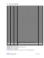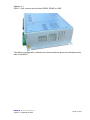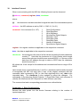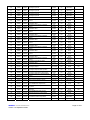
1
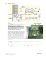
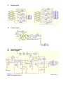
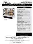
MCI/2
Measurement and
Control Interface
User Manual
Filename: um0064.doc
th
Date: 28 September
Version: 1.0
danntech - PROCESS INSTRUMENTATION
Version 1.0 September 2005
Document Number: UM0064
Part Number: DQ-MCI2/10/UE
Page 1 of 41
TABLE OF CONTENTS
1.
WHAT IS INCLUDED WITH YOUR MCI ................................................................................................... 4
1.
MCI/2 CD CONTENTS............................................................................................................................... 4
1.1.
1.2.
1.3.
1.4.
1.5.
1.6.
1.7.
APPLICATIONS ...................................................................................................................................... 4
BROCHURES ......................................................................................................................................... 4
MCI/2 USER MANUAL ........................................................................................................................... 4
MCI LOGGER ........................................................................................................................................ 4
RMF UTILS........................................................................................................................................... 4
SPREADSHEETS .................................................................................................................................... 4
USB DRIVERS ...................................................................................................................................... 4
2.
INTRODUCTION TO THE MCI/2............................................................................................................... 5
3.
APPLICATIONS ........................................................................................................................................ 6
4.
EDUCATIONAL POSSIBILITIES .............................................................................................................. 7
5.
FEATURES ................................................................................................................................................ 8
6.
SAFETY ................................................................................................................................................... 10
7.
GETTING UP AND RUNNING QUICKLY ............................................................................................... 11
8.
FRONT PANEL AND LED DETAILS ...................................................................................................... 12
9.
PHYSICAL CONNECTIONS ................................................................................................................... 13
10.
REMOVING THE COVER AND GETTING INSIDE ............................................................................. 15
11.
DIP SWITCHES.................................................................................................................................... 15
12.
JUMPER OPTION SELECTIONS........................................................................................................ 17
13.
COMMUNICATING WITH THE MCI/2 ................................................................................................. 20
14.
INSTALLING THE USB DRIVER......................................................................................................... 21
15.
COMMUNICATIONS WATCHDOG ..................................................................................................... 22
16.
ANALOGUE INPUTS........................................................................................................................... 23
17.
DIGITAL INPUTS ................................................................................................................................. 24
18.
COUNTER INPUT ................................................................................................................................ 24
19.
ANALOGUE OUTPUTS....................................................................................................................... 24
20.
RELAY OUTPUTS ............................................................................................................................... 24
21.
SOLID STATE RELAY OUTPUTS ...................................................................................................... 25
22.
DIGITAL OUTPUTS ............................................................................................................................. 25
23.
PULSE WIDTH MODULATED OUTPUTS........................................................................................... 26
24.
AUXILIARY I/O CONNECTORS.......................................................................................................... 27
danntech - PROCESS INSTRUMENTATION
Version 1.0 September 2005
Page 2 of 41
25.
TECHNICAL SPECIFICATIONS.......................................................................................................... 28
26.
DELIVERY CONFIGURATION ............................................................................................................ 30
27.
MOUNTING THE MCI/2 ....................................................................................................................... 32
28.
INPUT POWER .................................................................................................................................... 32
29.
OTHER FEATURES PLANNED FOR THE FUTURE.......................................................................... 32
30.
INTERFACE PROTOCOL.................................................................................................................... 33
danntech - PROCESS INSTRUMENTATION
Version 1.0 September 2005
Page 3 of 41
1. What is Included with your MCI
The MCI/2
User Manual
Power Cable
RS232 Interface Cable DSUB9 to DSUB9
USB Interface Cable
RS232 Interface Cable RJ45 to DSUB9
MCI/2 CD
1. MCI/2 CD Contents
1.1.
Applications
MCI application details (HTML), MCI applications (PDFs).
1.2.
Brochures
Various related product brochures.
1.3.
MCI/2 User Manual
PDF version of this user manual in high resolution and low resolution formats.
1.4.
MCI Logger
Logging and graphical display program for use
with the MCI/2.
Generalised data logging
program which allows the
MCI/2 to be used to log
and display graphically
up to eight analogue
inputs. Excel compatible
data file.
1.5.
RMF Utils
General Danntech Remote Magic and Modbus
communications test program for sending and
receiving Danntech RMF Communications or
Modbus commands.
Useful for preliminary testing and verifying that
the communications ports and connections are
working correctly.
1.6.
Spreadsheets
Excel Worksheet with Command and Register
Details.
1.7.
USB Drivers
Drivers for Win 2000, Win XP and Win 98.
danntech - PROCESS INSTRUMENTATION
Version 1.0 September 2005
Page 4 of 41
2. Introduction to the MCI/2
The Measurement and Control Interface (MCI) provides a powerful interface for doing
process control, data acquisition and logging.
In its basic form, the MCI is a “dumb” device, i.e. it must be used with a controller of some
sort – typically a PC but could be a PLC or any other controlling device.
RS232, RS485 and USB interfaces are provided for connecting to the MCI. Applications
which may require several data acquisition or control points - up to 32 MCIs can be can be
multi-dropped on one pair of twisted wires at a distance of up to 1 000 metres.
Customized applications can be developed using Visual Basic, Delphi and C. An Active-X
Control is also available for the Remote Magic Family Interface which allows direct use
with Microsoft Excel, Visual Basic, C or any other Windows program which supports
Active-X.
The MCI is useful in any laboratory where simple logging or control is required using a
personal computer. In this case the user can write a program to do exactly the job
required. Larger applications can be developed using more that one MCI spread over
1,000 metres with the two wire RS485 interface which allows the location of the hardware
close to the process. Communications signal isolation affords protection of the controlling
equipment against high industrial potentials, surges and spikes. Eighteen front panel
LEDs can be controlled and used to indicate various things.
Internally the MCI comprises of two printed circuit boards.
The Interface Board: at the bottom, which has the main processor and all the plug-in
screw terminal connections and the
Display Board: mounted in the top cover with the LEDs and auxiliary connectors
The MCI can be located simply on a desktop or screwed vertically to a panel. For
permanent mounting four holes are provided in the MCI bottom corners for bolting the MCI
securely vertically or horizontally.
danntech - PROCESS INSTRUMENTATION
Version 1.0 September 2005
Page 5 of 41
3. Applications
LABORATORY - Controlling of experiments, logging of results for analysis using other
applications, dynamic display of experimental results, temperature profile control.
PRODUCT TESTING - Production line quality assurance, linearity measurements of
input-output devices, logging of temperature performance, monitoring of products
undergoing burn-in.
ENERGY MANAGEMENT - Logging of energy consumption, switching of reactive
compensators, warning and monitoring of maximum demand, controlled load shedding,
timed switching.
TEST AND MEASUREMENT SYSTEMS - Easy integration with Labview and other
block diagram type programs. Direct program control provides sophisticated control of
purpose designed equipment. We can write specialized software to suit your
application.
PROCESS CONTROL - Level control, PID loops, temperature control, system
monitoring and logging.
EDUCATION - Waveform generation, introductory computer control, PID and ON/OFF
control system design, very low frequency synthesis, easy to use I/O platform for
projects, full PC source code for integration into new applications.
•
Galvanic isolation of plant signals from the controller.
•
Remote monitoring of a mixture of analogue and digital signals.
•
Simple remote control using the various inputs and outputs.
•
The concentration of a mixture of plant signals down to a pair of wires up to
1,000 metres long to minimise plant wiring thereby reducing the cost.
•
The distant switching of equipment without the need to run mains wiring.
•
The ability to provide a mixture of remote analogue measurement and control
outputs on any network.
Systems implemented using the Measurement and Control Interface – (details on the
MCI/2 CD or www.danntech.com website):
o Electroplating Control System
o Leach Plant Control System
o Crystallization Plant Control
o Irrigation Multi-Acid pH Control System
danntech - PROCESS INSTRUMENTATION
Version 1.0 September 2005
Page 6 of 41
o Distributed Ammonia Gas Monitoring System
o Stack Gas Monitoring System
o Automated Dilution of Hydrochloric Acid
o Galvanostatic/Potentiostatic Measurement Control System
o Fabric Dying Control System
o Cheese Factory Cleaning Cycle and Pasteurizer Monitoring
o 2 MW DC Furnace Monitoring
o Bacterial Growth Control System
o Mini-Cell Test System
o Motor Current Monitoring System
We can also write customised firmware for the MCI/2 to suit your application where
several units are required and the cost benefit can be realised. A once-off firmware
charge based on the time required implementing your unique functions and then a
standard cost thereafter.
4. Educational Possibilities
Computer Skills / IT Educators / Practical Programming
Now you can teach (or learn) how to develop more than Apassive@ programming and
computer skills. We have a simple, powerful and practical PC interface which
enables the student to actually switch things on and off, measure voltages or
currents, count events and detect switch closures.
The Measurement and Control Interface (MCI) adds a very practical and
immediately rewarding programming experience.
Using any of our software interfaces which are easy to understand, students can
quickly explore the power of using programs to perform practical and useful
functions.
We have several practical Aadd-ons@ such as:
Floor mat switch
Passive infra red sensor
Magnetic switches
Push-button switches
Proximity sensors
danntech - PROCESS INSTRUMENTATION
Version 1.0 September 2005
Page 7 of 41
Lamp
Buzzer
Temperature sensor
Level switch
Water flow valve
Motor and speed controller
Power supply
Supplied free of charge are various software examples and interface for use directly
with programs such as Excel, Visual Basic, Delphi, C++ and Visual C.
These tools gives the student practical meaning to programming and bridges the
gap between a powerful programmable device (the PC) and the real world. Say
goodbye to programs which just say Ahello world@ or are contrived to try and be of
practical use.
Our Measurement and Control Interface (MCI) can switch several high power
devices directly, measure up to eight voltage or current inputs, detect the status of
four switches, switch any of the 15 light emitting diodes (LEDs) amongst other
things.
Requires a free com port, a 486 or more powerful PC will do, along with the
creativity to explore.
5. Features
•
Eight 16 bit analogue inputs (0 to 10 V, 0 to 20 mA or 4 to 20 mA)
•
Eight digital inputs - four individually isolated, four with common 0V (0 to 12V or
0 to 30 V input)
•
One high speed sixteen bit counter input (0 to 12V or 0 to 30 V input, counter or
frequency modes)
•
Four relays (120 VAC/10 A, 240 VAC/6 A, 24 VDC/10 A)
•
Two solid state relays (240 VAC/3A)
•
Eight digital outputs - four individually isolated, four with common Vcc
connections
(40 V/100mA)
•
Two pulse width modulated outputs (30 V/50 mA)
•
Three analogue outputs
– one non-isolated, self powered 12 bits,
0 to 22.5 mA and 0 to 10.5 V
- two isolated, externally powered, 16 bits,
danntech - PROCESS INSTRUMENTATION
Version 1.0 September 2005
Page 8 of 41
derived from the PWM outputs, 0 to 22 mA and
0 to 11 V
•
Auxiliary 24 V 200 mA isolated DC supply for external devices.
•
Eighteen user controllable front panel LEDs with flashing capability
•
LED status indication of all digital inputs, digital and relay outputs on front panel
•
Communications fail relay LED indication and relay output
(120 VAC/10 A, 240 VAC/6 A, 24 VDC/10 A)
•
Interface -serial RS232, RS485 and USB – optically isolated from the MCI
internal circuitry
•
230 VAC powered (also 115 VAC by changing internal link)
•
Robust industrial enclosure
•
Plug-in screw terminal connections
•
Backward software compatibility with older version
•
Physical compatibility with older version – same mounting screws and same
plug-in connections.
danntech - PROCESS INSTRUMENTATION
Version 1.0 September 2005
Page 9 of 41
6. Safety
danntech - PROCESS INSTRUMENTATION
Version 1.0 September 2005
Page 10 of 41
7. Getting Up and Running Quickly
The quickest way to get up and
running is to find the communications
cable that you want to use – the DSUB
RS232, the RJ45 serial or the USB
connection cables. If you plan to use
the USB cable check out and install the
USB drivers.
Connect up the MCI and power it up.
The LEDs should flash once when
power is applied.
Now find and run the RMF_Utility.exe,
select the correct communications port
and 19,200 bits per second (if this is
the same as when delivered).
Set up up the Address, Command,
Register and Data as shown in the
picture, open the port and press the
Start/Send button. If all is well, the
MCI/2 should reply as shown – i.e. with
the reply:
1,130,1,0,32
If so, then all is OK. If there is no reply, check out all the settings and connections until a
reply is received.
danntech - PROCESS INSTRUMENTATION
Version 1.0 September 2005
Page 11 of 41
8. Front Panel and LED Details
Fifteen plus three LEDs are available to the user, these can be switched on or off
or made to flash when switched on or off. Each LED can be configured to flash or
not and then when switched on or off will either remain on or flash. Label areas
are provided for each LED so that they can be labelled to suit the application.
There is also a buzzer available inside the MCI which can be controlled.
All the input and output states are also indicated using the row of green LEDs.
All of the LED outputs (not isolated) and switch inputs are also made available on
the Auxiliary connectors for advanced users and future digital output expansion.
danntech - PROCESS INSTRUMENTATION
Version 1.0 September 2005
Page 12 of 41
Each LED has a power-up setting as well as a power-up flash control setting.
9. Physical Connections
danntech - PROCESS INSTRUMENTATION
Version 1.0 September 2005
Page 13 of 41
danntech - PROCESS INSTRUMENTATION
Version 1.0 September 2005
Page 14 of 41
10. Removing the Cover and Getting Inside
Four quarter-turn screws are used to fasten the lid.
11. DIP Switches
SW1 selects the following:
SW1.1 - Communications speed:
0 (off) = 19,200 or 115,200 bits/sec
1 (on) = 9,600 or 57,600 bits/sec
SW1.2 – not used:
SW1.3 – Communications speed range:
(used with SW1.1)
0 (off) = low range 9,600 and 19,200 bits/sec
1 (on) = high range 57,600 or 115,200 bits/sec
SW1.4 to SW1.8 - Device address -
Binary with SW1.4 = MSB and SW1.8 = LSB
SW2 selects the following:
SW2.1 – Communications medium select – always ON
danntech - PROCESS INSTRUMENTATION
Version 1.0 September 2005
Page 15 of 41
SW2.2 – Select Danntech Remote Magic
Family Communications Protocol or Modbus
Only SW2.4 is used:
Manual input calibration control
0 (off) = normal operation
1 (on) = analogue input calibration
SW1
Communications Baudrate
(depends on range selected)
Communications Baudrate
Range
1
3
Not Used
2
Address MSB
4
5
6
7
8
Address LSB
SW2
Always ON – selects RS232,
RS485 and USB
RMF or Modbus Select
OFF
9,600 or
57,600
ON
19,200 or
115,200
low range
high range
OFF
ON
Always ON
1
Not Used
2
3
Manual Input Calibration
4
Not Used
Not Used
Not Used
Not Used
5
6
7
8
danntech - PROCESS INSTRUMENTATION
Version 1.0 September 2005
0 (off) = RMF
1 (on) = Modbus
Danntech
RMF Protocol
Modbus
Normal
Calibrate
Page 16 of 41
12.
Jumper Option Selections
Analogue Inputs:
Analogue Input #1
0-10 V
4-20 mA
0-20 mA
J1/1
A
B
B
J1/2
out
in
out
J1/3
out
in
out
Analogue Input #2
0-10 V
4-20 mA
0-20 mA
J2/1
A
B
B
J2/2
out
in
out
J2/3
out
in
out
Analogue Input #3
0-10 V
4-20 mA
0-20 mA
J3/1
A
B
B
J3/2
out
in
out
J3/3
out
in
out
Analogue Input #4
0-10 V
4-20 mA
0-20 mA
J4/1
A
B
B
J4/2
out
in
out
J4/3
out
in
out
Analogue Input #5
0-10 V
4-20 mA
0-20 mA
J5/1
A
B
B
J5/2
out
in
out
J5/3
out
in
out
Analogue Input #6
0-10 V
4-20 mA
0-20 mA
J6/1
A
B
B
J6/2
out
in
out
J6/3
out
in
out
Analogue Input #7
0-10 V
4-20 mA
0-20 mA
J7/1
A
B
B
J7/2
out
in
out
J7/3
out
in
out
Analogue Input #8
0-10 V
4-20 mA
0-20 mA
J8/1
A
B
B
J8/2
out
in
out
J8/3
out
in
out
danntech - PROCESS INSTRUMENTATION
Version 1.0 September 2005
Page 17 of 41
Digital Inputs:
Digital Input #1
Digital Input #2
Digital Input #3
Digital Input #4
Digital Input #5
Digital Input #6
J17
0-12 V
in
0-30 V
out
J18
0-12 V
in
0-30 V
out
J19
0-12 V
in
0-30 V
out
J20
0-12 V
in
0-30 V
out
J12
0-12 V
in
0-30 V
out
J13
0-12 V
in
0-30 V
out
0-12 V
0-30 V
J14
in
out
J15
0-12 V
in
0-30 V
out
Digital Input #7
Digital Input #8
danntech - PROCESS INSTRUMENTATION
Version 1.0 September 2005
Page 18 of 41
Counter Inputs:
Counter Input
J16
0-12 V
in
0-30 V
Out
Auxiliary Analogue Outputs:
Iout1
Iout2
J13/2
J14/2
danntech - PROCESS INSTRUMENTATION
Version 1.0 September 2005
0-11 V
A
A
0-22 mA
B
B
Page 19 of 41
13.
Communicating with the MCI/2
Communication with the MCI can be done in any of three ways – RS232, RS485
or USB. RS232 and RS485 connections are available on the 9 way DSUB and
the RJ45 connectors. A two way plug-in screw terminal connector is provided for
RS485 connection.
Only one device can be connected using the RS232 or USB connections but up
to 32 devices (MCIs or any other Danntech Remote Magic Family products) can
be connected using RS485.
9 Way DSUB Female Connector
(On MCI) Details
Pin
Description
1
Not used
2
Rx - RS232
3
Tx - RS232
4
DATA+ RS485
5
0V
6
+5 V
7
Not used
8
Not used
9
DATA- RS485
danntech - PROCESS INSTRUMENTATION
Version 1.0 September 2005
RJ45 Female Connector
(On MCI) Details
Page 20 of 41
14.
Installing the USB Driver
In the USB Drivers folder on the MCI/2 CD you will find two documents:
Windows_XP_Installation_Guide.pdf and Windows_98_Installation_Guide.pdf.
These documents have details regarding the USB driver installation.
When using Win XP, plug in the MCI USB cable and you will be prompted to
install drivers for the FT232BM which is the device used in the MCI/2.
Generally most MCI/2 users will require the second driver type which is the
virtual COM port (VCP) driver. The VCP drivers emulate a standard PC COM
port. These can be communicated with in the same manner as any other COM
port on the PC.
Under Windows XP, the Found New Hardware Wizard should be used to install
devices when they are connected to the PC for the first time as this is the
recommended procedure for reliable device operation.
You need to install the drivers found on the MCI/2 CD in the “USB Drivers” folder.
danntech - PROCESS INSTRUMENTATION
Version 1.0 September 2005
Page 21 of 41
15.
Communications Watchdog
The MCI/2 has a serial communications watchdog which provides a way of
making sure that the MCI/2 and the controller keep working correctly.
Each time the MCI/2 responds to a command (transmits) the internal watchdog is
reset.
While the watchdog is reset periodically the red COMMS FAIL LED remains off
and the COMMS FAIL relay remains closed. When the MCI/2 stops transmitting
for whatever reason, for a preset period of time, then the watchdog times out and
the red COMMS FAIL LED comes on and the COMMS FAIL relay opens.
The trimpot adjustment when fully anti-clockwise produces a watchdog timeout of
1 second, fully clockwise produces a watchdog timeout of around 20 seconds.
danntech - PROCESS INSTRUMENTATION
Version 1.0 September 2005
Page 22 of 41
16.
Analogue Inputs
Calibration SW2.4 used for manual input calibration
control (OFF=normal operation,
ON=analogue input calibration). When
manual calibration is selected the rotary
switch SW3 selects the channel being
calibrated and SW4 sets the zero and
SW5 the full scale input values.
Inject the value you wish to have as zero
for the input being calibrated, allow a few
seconds to stabilize and then press the
Set Zero button. Then inject the value
you wish to have as the full scale value
and after a few seconds press the Set
Full Scale button. This sets up the value
read back from the analogue input as 0 for the zero value and 65535 for the full
scale value.
The LED near the CPU will flash three times when calibration measurements
successful.
This same procedure can be done using the calibrate command and registers 84
through 99 for situations where access to the MCI/2 is difficult.
danntech - PROCESS INSTRUMENTATION
Version 1.0 September 2005
Page 23 of 41
17.
Digital Inputs
18.
Counter Input
19.
20.
Analogue Outputs
Relay Outputs
danntech - PROCESS INSTRUMENTATION
Version 1.0 September 2005
Page 24 of 41
21.
Solid State Relay Outputs
22.
Digital Outputs
danntech - PROCESS INSTRUMENTATION
Version 1.0 September 2005
Page 25 of 41
23.
Pulse Width Modulated Outputs
danntech - PROCESS INSTRUMENTATION
Version 1.0 September 2005
Page 26 of 41
24.
Auxiliary I/O Connectors
Auxiliary Connector #1
danntech - PROCESS INSTRUMENTATION
Version 1.0 September 2005
Auxiliary Connector #2
Page 27 of 41
25.
Technical Specifications
Analogue Inputs:
Eight analogue inputs
Sixteen bit resolution
10 Hz input filter
Non-isolated with common zero volt connection
Link selectable current or voltage options
0 to 20 mA or 4 to 20 mA with 100 Ω input resistance
0 to 10 V with 470 kΩ input resistance
Input zero and full scale adjustment manually by means of rotary select switch and zero and full scale
buttons or using software and the calibrate commands
Digital Inputs:
Eight digital inputs - four individually isolated, four with common 0V (0 to 12V or 0 to 30 V input)
Link selectable input voltage range options.
Voltage input option 0 to 12 V - Vin < 1 V = digital 0
Vin > 4 V = digital 1
Input resistance = 3.3 kΩ
Voltage input option 0 to 30 V - Vin < 8 V = digital 0
Vin > 13 V = digital 1
Vin max = 30 V
Input resistance = 15 kΩ
Counter Inputs:
One sixteen bit counter
Isolated input 0 to 50 kHz
Link selectable voltage or current options
Voltage input option - Vin < 1 V = digital 0
Vin > 4 V = digital 1
Vin max = 30 V
input resistance = 1 kΩ
Current input option - Iin < 10 mA = digital 0
Iin > 18 mA = digital 1
Iin max = 30 mA
input resistance = 270 Ω
Analogue Output:
One analogue output
Ten bit resolution
10 Hz output filter
Non-isolated with common zero volt connection
Both current and voltage outputs available
0 to 20 mA or 4 to 20 mA with 500 Ω maximum load resistance
0 to 10 V with 2 kΩ minimum load resistance
Offset and span adjustment with multiturn trimpots
PWM Outputs:
Two pulse width modulated outputs
TTL 0 V to 5 V levels
Easy conversion to two eight bit analogue outputs
Frequency controllable from 50 Hz to 14 460 Hz in 255 steps
Duty cycle controllable from 0 to 100 % in 255 steps
Digital Outputs:
Four individually isolated digital outputs
Independent uncommitted NPN transistors with open collector and open emitter
danntech - PROCESS INSTRUMENTATION
Version 1.0 September 2005
Page 28 of 41
Output transistor rating 30 V Vce max and 150 mA Ic max
Relay Outputs:
Four relay outputs
Both normally open and normally closed contacts available
Potential free contacts
Contacts AC rated at 250 VAC at 10 A
Contacts DC rated at 220 V DC at 1 A
RC series snubbing across both contacts of each relay
Snubber 10 nF 630 V capacitor in series with 100 Ω two watt resistor
Locations for the addition of transorbs or MOVs if required
Solid State Relay Outputs:
Two solid state relay outputs
Rated at 240 VAC at 3 A
Triac zero voltage switching
General:
Robust industrial enclosure
Power requirements 230 V or 115 VAC 50/60 Hz "10 % at 20 VA
Built-in auxiliary 24 V 200 mA isolated DC supply for external devices
Operating temperature 0 to 70 EC
Plug-in screw terminal connections
Maximum wire size 1.5 mm2
9 way DSUB interface connection
Vertical or horizontal mounting with four M5 or M6 screws for which holes are provided
Dimensions 290 x 190 x 62 mm (length x width x height)
Colour - powder coated white with front panel decal
MCI/2 weight is 3 kg
Packaging – white foam lined self-locking cardboard box 370 x 330 x 130 mm (length x width x height)
Weight of packaged MCI/2 with cables and user manual is 4 kg.
danntech - PROCESS INSTRUMENTATION
Version 1.0 September 2005
Page 29 of 41
26.
Delivery Configuration
RM
Modbus
Modbus
Read
Write
Register
Reg
Reg
#
17
Address
40017
Address
60017
28
40028
29
30
Default
Description
Value
Digital Output Power-up Word
0
60029
Relay #1 Pulse Value Power-up Setting
0
40029
60030
Relay #2 Pulse Value Power-up Setting
0
40030
60030
Relay #3 Pulse Value Power-up Setting
0
31
40031
60031
Relay #4 Pulse Value Power-up Setting
0
32
40032
60032
Open Collector Output #1 Pulse Value Power-up Setting
0
33
40033
60033
Open Collector Output #2 Pulse Value Power-up Setting
0
0
34
40034
60034
Open Collector Output #3 Pulse Value Power-up Setting
35
40035
60035
Open Collector Output #4 Pulse Value Power-up Setting
0
36
40036
60036
Solid State Relay #1 Pulse Value Power-up Setting
0
0
37
40037
60037
Solid State Relay #2 Pulse Value Power-up Setting
45
40045
60045
Counter Timebase Value (n x 100 mSecs)
59
40059
60059
Counter Mode Power-up Value
60
40060
60060
Counter Timebase Power-up Value
62
40062
60062
LED Output Power-Up Word
0
64
40064
60064
Digital Output Toggle Control Power-up Control Word
0
67
40067
60067
LED Flash Control Register Power-up Control Word
0
69
40069
60069
PWM Mode Power-up Value
1
73
40073
60073
PWM Output #1 Duty Cycle Power-up Value
65535
75
40075
60075
PWM Output #2 Duty Cycle Power-up Value
65535
101
40101
60101
Analogue Output Power-up Value
0
106
40106
60106
0
108
40108
60108
Auxiliary LED/Buzzer Output Word Power-up Word
Auxiliary LED/Buzzer Flash Control Register Power-up Control
Word
100
2
100
Analogue Inputs - all 0 to 10 V
Analogue Output - 0 to 10.5 V and 0 to 22.5 mA
Digital Inputs - all 0 to 30 VDC
Counter Input - 0 to 30 VDC
Auxiliary analogue outputs Iout1 and Iout2 - 0 to 22 mA (approximate)
danntech - PROCESS INSTRUMENTATION
Version 1.0 September 2005
Page 30 of 41
0
Address = 1
SW2.1 = ON, comms can be either RS232, RS485 or USB.
The delivery configuration, address and communications speed are indicated on the
side of the MCI/2.
danntech - PROCESS INSTRUMENTATION
Version 1.0 September 2005
Page 31 of 41
27.
Mounting the MCI/2
Distance between mounting hole centres 272 x 152 mm, with maximum 4 mm
shank diameter screw or M6 bolt.
28.
Input Power
The MCI/2 is normally configured for 230
VAC unless otherwise clearly marked
otherwise. The soldered wire links of J22
must be changed for 115 VAC operation.
The input mains supply has a protection
fuse, mains filter and surge protection. The
fuse recommended is 20 x 5 mm, 3 A slow
blow, 230 VAC.
29.
Other Features Planned for the Future
29.1.
29.2.
29.3.
29.4.
29.5.
29.6.
29.7.
Internal GSM modem.
Stand-alone data logging and GSM modem connection.
Second serial port for connection to additional serial communication
devices.
128 x 64 LCD display.
24 or 12 VDC powered.
Low power option for battery powered data logging.
Compact DIN rail mounting version
danntech - PROCESS INSTRUMENTATION
Version 1.0 September 2005
Page 32 of 41
30.
Interface Protocol
When communicating with the MCI the following format must be observed:
@address, command, register, data, checksum
where:
@-
this character must be transmitted to signal the start of the command sequence
address - the MCI address as set by SW1.4 - SW1.8, (0 to 31).
command - the command (0 to 127):
1
2
3
4
5
6
7
8
9
Read Configuration
Read Registers
Write Registers
Synchronize Digital Outputs
Read Run Time
Read Raw Data
Read Bulk Data
Identify All Attached
Synchronize Digital Outputs
register - the register number as applicable to the respective command.
data - the data as applicable to the respective command.
checksum - the checksum is the sum of all the values (excluding the start character)
modulo 216. Note that the checksum is a 16-bit number which wraps
around through zero should the sum exceed 65535 i.e. if the sum of the
data from the address through to data is 65537 then the checksum
should be sent as 1.
All values are 16-bit except for the address and command and have a range of 0 to
65535.
Upon receipt of any command between 1 and 9 (i.e. checksum matches and command
is recognized) the MCI will reply with a copy of the original command with the
command value increased by 128 (i.e. the most significant bit is set); data is the
requested data. The checksum is also updated to reflect the changes. For
commands 4 (Synchronize Digital Outputs), 7 (Read Bulk Data) and command 8
(Identify All Attached) the MCI response is a little different (see later).
The command set and corresponding parameters are outlined below.
Command = 1, Read Configuration:
Returns the data preset into the device firmware relating to the number of
inputs/outputs etc.
danntech - PROCESS INSTRUMENTATION
Version 1.0 September 2005
Page 33 of 41
register =
address of the register to be read-
0-
Device part number code (12 for this device)
1-
Firmware version number in the format zzzz/10 so 10 means version 1.0 and
43 version 4.3
2-
Number of digital outputs this unit has (10)
3-
Number of digital inputs this unit has (4)
4-
Number of analogue outputs this unit has (34 = 2-analogue output and start-up
register + 2- digital output and start-up register + 20-pulse dividers and start-up
registers + 8-PWM outputs and start-up registers + 2-counter value and mode)
5-
Number of analogue inputs this unit has (8)
6-
Imbedded serial number (can be written once and thereafter can only be read).
data = any value when transmitted to the device (usually zero), contains the requested
configuration data upon return.
[The digital and analogue inputs and outputs relate to the Modbus protocol in which
the digital outputs are read and write, digital inputs are read only, analogue inputs are
read only and the analogue outputs are read and write.]
Command = 2 and 3, Read and Write Registers:
Read and Write Registers - Commands 2 and 3
2 = read
register
3 = write
register
Allows access to the all the input and current output values and the DIP switch settings
Allows writing to the all the output registers
Modbus
Modbus
Powerup
RM
Read
Write
Value
RM
Register
Reg
Reg
from
Power-up
#
Address
Address
Range
EERAM
RM Mode
1
40001
60001
Digital Input #1 (0 = off, 1 = on)
0 to 1
no
Read Only
2
40002
60002
Digital Input #2 (0 = off, 1 = on)
0 to 1
no
Read Only
3
40003
60003
Digital Input #3 (0 = off, 1 = on)
0 to 1
no
Read Only
4
40004
60004
Digital Input #4 (0 = off, 1 = on)
5
40005
60005
Digital Input Word
6
40006
60006
7
40007
8
9
Description
0 to 1
no
Read Only
0 to 255
no
Read Only
Relay #1 (0 = off, 1 = on)
0 to 1
yes
60007
Relay #2 (0 = off, 1 = on)
0 to 1
yes
40008
60008
Relay #3 (0 = off, 1 = on)
0 to 1
40009
60009
Relay #4 (0 = off, 1 = on)
0 to 1
danntech - PROCESS INSTRUMENTATION
Version 1.0 September 2005
Register #
yes
Read and
Write
Read and
Write
Read and
Write
bit #0 of reg
17
bit #1 of reg
17
bit #0 of reg
17
yes
Read and
bit #0 of reg
Page 34 of 41
10
40010
60010
Opto Output #1 (0 = off, 1 = on)
0 to 1
yes
11
40011
60011
Opto Output #2 (0 = off, 1 = on)
0 to 1
yes
12
40012
60012
Opto Output #3 (0 = off, 1 = on)
0 to 1
yes
13
40013
60013
Opto Output #4 (0 = off, 1 = on)
0 to 1
yes
14
40014
60014
Solid State Relay #1 (0 = off, 1 = on)
0 to 1
yes
15
40015
60015
Solid State Relay #2 (0 = off, 1 = on)
yes
16
40016
60016
Digital Output Word
17
40017
60017
Digital Output Power-up Word
0 to 1
0 to
65535
0 to
65535
18
40018
60018
Relay #1 Pulse Value
19
40019
60019
Relay #2 Pulse Value
20
40020
60020
Relay #3 Pulse Value
21
40021
60021
Relay #4 Pulse Value
22
40022
60022
Opto Output #1 Pulse Value
23
40023
60023
Opto Output #2 Pulse Value
24
40024
60024
Opto Output #3 Pulse Value
25
40025
60025
Opto Output #4 Pulse Value
26
40026
60026
Solid State Relay #1 Pulse Value
27
40027
60027
Solid State Relay #2 Pulse Value
28 to 37
0 to
65535
0 to
65535
0 to
65535
0 to
65535
0 to
65535
0 to
65535
0 to
65535
0 to
65535
0 to
65535
0 to
65535
yes
yes
yes
yes
yes
yes
yes
yes
yes
yes
yes
yes
Write
17
Read and
Write
Read and
Write
Read and
Write
Read and
Write
Read and
Write
Read and
Write
Read and
Write
Read and
Write
bit #0 of reg
17
bit #0 of reg
17
bit #0 of reg
17
bit #0 of reg
17
bit #0 of reg
17
bit #0 of reg
17
Read and
Write
Read and
Write
Read and
Write
Read and
Write
Read and
Write
Read and
Write
Read and
Write
Read and
Write
Read and
Write
Read and
Write
17
28
29
30
31
32
33
34
35
36
37
Digital Output Power-up registers
38
40038
60038
39
40039
60039
40
40040
60040
41
40041
60041
42
40042
60042
43
40043
60043
44
PWM Output Frequency (for both
PWM outputs)
PWM Output Frequency Power-up
Value (for both PWM outputs)
PWM Output #1 Duty Cycle
PWM Output #1 Duty Cycle Power-up
Value
PWM Output #2 Duty Cycle
PWM Output #2 Duty Cycle Power-up
Value
0 to 255
yes
0 to 255
yes
0 to 255
yes
0 to 255
yes
0 to 255
yes
0 to 255
yes
Read and
Write
Read and
Write
Read and
Write
Read and
Write
Read and
Write
Read and
Write
yes
Read and
Write
60
59
39
41
43
not used
45
40045
60045
Counter Timebase Value
46
40046
60046
Counter Value
0 to
65535
0 to
65535
47
40047
60047
Counter Mode
0, 1 or 2
yes
Read Only
Read and
Write
48
40048
60048
Analogue Input #1
0 to 1023
no
Read Only
49
40049
60049
Analogue Input #2
0 to 1023
no
Read Only
danntech - PROCESS INSTRUMENTATION
Version 1.0 September 2005
no
Page 35 of 41
50
40050
60050
Analogue Input #3
0 to 1023
no
Read Only
51
40051
60051
Analogue Input #4
0 to 1023
no
Read Only
52
40052
60052
Analogue Input #5
0 to 1023
no
Read Only
53
40053
60053
Analogue Input #6
0 to 1023
no
Read Only
54
40054
60054
Analogue Input #7
0 to 1023
no
Read Only
55
40055
60055
Analogue Input #8
0 to 1023
no
Read Only
56
40056
60056
Analogue Output
0 to 1023
yes
Read and
Write
57
40057
60057
Analogue Output Power-up Value
58
40058
60058
DIP switch #1 setting in binary
0 to 255
no
Read Only
59
40059
60059
Counter Mode Power-up Value
0 to
65535
yes
Read and
Write
60
40060
60060
Counter Timebase Power-up Value
61
40061
60061
LED Output Word
0 to
65535
yes
Read and
Write
62
62
40062
60062
LED Output Power-Up Word
63
40063
60063
0 to
65535
yes
Read and
Write
65
64
40064
60064
Digital Output Toggle Control Word
Digital Output Toggle Control Powerup Control Word
65
40065
60065
Counter Overflow Register
0 to
65535
no
Read and
Write
66
40066
60066
67
40067
60067
LED Flash Control Register
LED Flash Control Register Power-up
Control Word
0 to
65535
0 to
65535
68
40068
60068
PWM Mode
0 or 1
yes
69
40069
60069
PWM Mode Power-up Value
0 or 1
yes
70
40070
60070
71
40071
60071
PWM Output Frequency (for both
PWM outputs)
PWM Output Frequency Power-up
Value (for both PWM outputs)
72
40072
60072
73
40073
60073
74
40074
60074
75
40075
60075
PWM Output #2 Duty Cycle
PWM Output #2 Duty Cycle Power-up
Value
0 to
65535
0 to
65535
0 to
65535
0 to
65535
0 to
65535
0 to
65535
76
40076
60076
Analogue Input #1
77
40077
60077
Analogue Input #2
78
40078
60078
Analogue Input #3
79
40079
60079
Analogue Input #4
danntech - PROCESS INSTRUMENTATION
Version 1.0 September 2005
PWM Output #1 Duty Cycle
PWM Output #1 Duty Cycle Power-up
Value
0 to
65535
0 to
65535
0 to
65535
0 to
65535
yes
yes
Read and
Write
Read and
Write
Read and
Write
Read and
Write
yes
Read and
Write
Read and
Write
Read and
Write
Read and
Write
Read and
Write
Read and
Write
no
Read Only
no
Read Only
no
Read Only
no
Read Only
yes
yes
yes
yes
yes
57
67
69
69
71
73
75
Page 36 of 41
80
40080
60080
Analogue Input #5
81
40081
60081
Analogue Input #6
82
40082
60082
Analogue Input #7
83
40083
60083
Analogue Input #8
0 to
65535
0 to
65535
0 to
65535
0 to
65535
84
40084
60084
85
40085
60085
86
40086
60086
87
40087
60087
88
40088
60088
89
40089
60089
90
40090
60090
91
40091
60091
92
40092
60092
93
40093
60093
94
40094
60094
95
40095
60095
96
40096
60096
97
40097
60097
98
40098
60098
99
40099
60099
Analogue Input #1 Zero Calibrate
Value
Analogue Input #1 Full Scale
Calibrate Value
Analogue Input #2 Zero Calibrate
Value
Analogue Input #2 Full Scale
Calibrate Value
Analogue Input #3 Zero Calibrate
Value
Analogue Input #3 Full Scale
Calibrate Value
Analogue Input #4 Zero Calibrate
Value
Analogue Input #4 Full Scale
Calibrate Value
Analogue Input #5 Zero Calibrate
Value
Analogue Input #5 Full Scale
Calibrate Value
Analogue Input #6 Zero Calibrate
Value
Analogue Input #6 Full Scale
Calibrate Value
Analogue Input #7 Zero Calibrate
Value
Analogue Input #7 Full Scale
Calibrate Value
Analogue Input #8 Zero Calibrate
Value
Analogue Input #8 Full Scale
Calibrate Value
0 to
65535
0 to
65535
0 to
65535
0 to
65535
0 to
65535
0 to
65535
0 to
65535
0 to
65535
0 to
65535
0 to
65535
0 to
65535
0 to
65535
0 to
65535
0 to
65535
0 to
65535
0 to
65535
100
40100
60100
Analogue Output
0 to 4095
yes
101
40101
60101
Analogue Output Power-up Value
yes
102
40102
60102
103
40103
60103
Analogue Output Zero Offset Value
Analogue Output Full Scale Multiplier
Value
0 to 4095
0 to
65535
0 to
65535
yes
Read and
Write
Read and
Write
Read and
Write
Read and
Write
104
40104
60104
DIP switch #2 setting in binary
0 to 255
no
Read Only
105
40105
60105
0 to
65535
yes
Read and
Write
106
40106
60106
107
40107
60107
108
40108
60108
Aux LED/Buzzer Output Word
Aux LED/Buzzer Output Word Powerup Word
Aux LED/Buzzer Flash Control
Register
Aux LED/Buzzer Flash Control
Register Power-up Control Word
109
40109
60109
Push Button Switch Input Word
danntech - PROCESS INSTRUMENTATION
Version 1.0 September 2005
0 to
65535
0 to
65535
0 to
65535
no
Read Only
no
Read Only
no
Read Only
no
Read Only
yes
yes
yes
yes
yes
yes
yes
yes
yes
yes
yes
yes
yes
yes
yes
yes
yes
Read and
Write
Read and
Write
Read and
Write
Read and
Write
Read and
Write
Read and
Write
Read and
Write
Read and
Write
Read and
Write
Read and
Write
Read and
Write
Read and
Write
Read and
Write
Read and
Write
Read and
Write
Read and
Write
yes
Read and
Write
Read and
Write
no
Read Only
yes
101
106
108
Page 37 of 41
Using the Pulsing Features of the Digital Outputs
All the digital outputs can be used in the pulse output mode. In this mode the output pulse rate can be
set by writing to the respective Aoutput pulse value register@. A specified power-up pulse value can also
be specified for each digital output which is accessed by the respective Aoutput pulse power-up value@
which is stored in EERAM.
It is recommended that to begin with 0 is written to registers 63 and 64 to make sure that the
output pulsing is initially disabled.
Simple on/off control can be used by writing a 0 or a 1 to the various output registers. Using values other
than 0 or 1 the other pulsing features can be used. The various states are determined by writing other
values to the digital outputs. These are best described using a table format:
bit 3 = enables or disables bit 2
bit 2 = the new pulsing output state
bit 1 = enables or disables bit 1
bit 0 = new output state
bit 3
bit 2
bit 1
bit 0
Decimal
0
0
0
0
0
If 63 = 0 then simple on/off. If pulsing is enabled then will
set output OFF until the next state changed as defined by
the pulse settings.
0
0
0
1
1
If 63 = 0 then simple on/off. If pulsing is enabled then will
set output ON until the next state changed as defined by the
pulse settings.
0
0
1
0
2
Leaves pulse state unchanged - sets output OFF. Same
effect as writing 0.
0
0
1
1
3
Leaves pulse state unchanged - sets output ON. Same
effect as writing 1.
0
1
0
0
4
No effect.
0
1
0
1
5
No effect.
0
1
1
0
6
Same effect as writing 0.
0
1
1
1
7
Same effect as writing 1.
1
0
0
0
8
Disable pulsing and leave output in its current state.
1
0
0
1
9
Disable pulsing and leave output in its current state.
1
0
1
0
10
Disable pulsing and set output OFF.
1
0
1
1
11
Disable pulsing and set output ON.
1
1
0
0
12
Enable pulsing and leave output in its current state.
1
1
0
1
13
Enable pulsing and leave output in its current state.
1
1
1
0
14
Enable pulsing and set output OFF initially.
1
1
1
1
15
Enable pulsing and set output ON initially.
Description
Note that register 63 can be used to enable or disable pulsing on all of the digital outputs all together.
Register 64 simply defines weather the various digital outputs will have the pulsing feature enable or
disabled at power-up. This value is stored in EERAM.
danntech - PROCESS INSTRUMENTATION
Version 1.0 September 2005
Page 38 of 41
Command = 4, Read and Write Registers:
Calibrate analogue inputs and outputs.
Command = 5, Read Run Time:
Returns the approximate length of time the MCI has been running since the last power-up.
register =
0123-
address of the register to be readseconds
minutes
hours
days
data = returns the data requested
Command = 6, Read Raw Data:
Returns the unscaled or uncalibrated data read from the analogue inputs.
Command = 7, Read Bulk Data:
Allows the user to read blocks of data instead of single data values.
The command structure is the same as before i.e.
@address, command, register, data, checksum
where command is the allocated command number = 7
Now instead of simply sending all the registers back to the control module the MCI will now send a range
of registers. These registers are specified by a start address contained in the register parameter and an
end address stored in the data portion of the command string. Having received the command the
module will transmit the registers in a single stream of values, separated by commas and terminated with
a CR/LF combination.
After the stream of data the original command is echoed to the host with the command value updated as
normal (128 added to the command value). The Adata@ returned in the echoed command however is the
checksum of the block transfer data. This echoed command will be ended with the standard checksum
validating the echoed command and its data.
Thus with the MCI at address 0, to obtain the analogue input values with 9.32 V applied to inputs 1 to 4
and 0.988 V applied to inputs 5 to 8 the following command could be used:
@0,7,48,55,110
The reply would be:
953,952,963,952,99,99,99,100
0,135,48,4217,4400
Where the first line 953, ..... 100 represent the analogue input values (0 to 1023) and the second line can
be broken down as follows:
danntech - PROCESS INSTRUMENTATION
Version 1.0 September 2005
Page 39 of 41
0
135
=
=
48
4217
4400
=
=
=
the echo of the device address
the command echoed with the highest bit set i.e. 128 added to the original command
sent to the MCI
the echo of the starting register address
the checksum of the first line values
the checksum of the second line values
If the MCI detects a discrepancy between the calculated checksum and the transmitted checksum then
the command is ignored. The master must then time out and take appropriate action.
If the master does not receive the correct reply it must assume that the command was not received by
the slave.
Command = 8, Identify All Attached:
This command allows the control module to quickly identify all modules attached to the RS485 interface.
The command structure is the same as before i.e.
@address, command, register, data, checksum
Where the address, the register and the data values are ignored (so any values can be sent) and the
checksum is calculated as usual.
In response to this command, each attached MCI replies after a delay of its address*10 mSec. This
ensures that within 450 mSecs all the modules attached are identified (maximum of 32 modules).
The various attached modules would reply with the following:
address, device part number code, checksum
Where the address is the replying module address and the device part number is 12.
Command = 9, Synchronize Digital Outputs:
This command provides a means of synchronizing any of the digital outputs so that they switch on and
off together. It works as follows:
@address, 9, outputselect, syncvalue, checksum
Where the address and checksum are calculated as for the other commands and
outputselect = a word 0 to 65535 in which the setting of the various bits determines which of the digital
outputs are to be synchronized.
Bit 0
Bit 1
Bit 2
Bit 3
Bit 4
Bit 5
Bit 6
Bit 7
Bit 8
Bit 9
danntech - PROCESS INSTRUMENTATION
Version 1.0 September 2005
=
=
=
=
=
=
=
=
=
=
Relay #1
Relay #2
Relay #3
Relay #4
Open Collector Output #1
Open Collector Output #2
Open Collector Output #3
Open Collector Output #4
Solid State Relay #1
Solid State Relay #2
Page 40 of 41
syncvalue =
a word value made up with the individual bits indicate what value 0 or 1 the
selected output should inherit.
When the MCI receives this command it analyses which outputs are to be affected (as determined by the
outputselect parameter) and adjusts the internal counters used on each output such that they will toggle
at the same time starting with a Aset@ state. The other outputs are not affected by this command and
continue operating how they were last configured.
So for example using an MCI at address 1, to synchronize Relay #1 and Open Collector Output #1 so
that Relay #1 is on and Open Collector Output #1 is off the following command is used:
@1,9,17,1,28
The 17 is derived by setting bits 0 (Relay #1) and 4 (Open Collector Output #1) and the 1 is to set bit 4 in
the OFF state and bit 0 in the ON state at synchronization.
danntech - PROCESS INSTRUMENTATION
Version 1.0 September 2005
Page 41 of 41