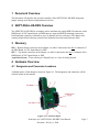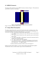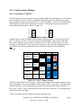
1
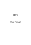
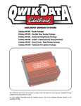
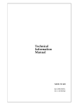
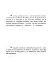
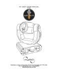
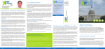
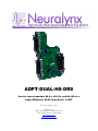
ADPT ADPT-DUAL-HS-DRS DRS Used to connect multiple HS HS-8’s, HS-16’s, and HS-18’s 18’s to a single DRS board board, AC/DC Input Board, or ERP. Revision 1.00: July 01, 2009 Neuralynx, Inc. 105 Commercial Drive, Bozeman, MT 59715 Phone 406.585.4542 • Fax 406.585.9034 www.Neuralynx.com [email protected] Table of Contents 1 2 3 4 Document Overview ............................................................................................................... 3 ADPT-DUAL-HS-DRS Overview ......................................................................................... 3 Glossary .................................................................................................................................. 3 Hardware Overview ................................................................................................................ 3 4.1 Designator and Connector Locations ............................................................................... 3 4.2 MDR-50 Connector .......................................................................................................... 4 4.3 Header Pin Descriptions ................................................................................................... 4 4.3.1 Custom Jumper Settings ........................................................................................... 5 5 Installation............................................................................................................................... 6 5.1 Tightening Screws ............................................................................................................ 6 List of Figures and Tables Figure 4-1 Labeled Adapter ......................................................................................................... 3 Figure 4-2 Acquisition Side MDR-50 Connector pin out .......................................................... 4 Figure 4-3 Stimulus Jumper Blocks ............................................................................................ 5 Figure 4-4 Reference Jumper Block ............................................................................................ 6 Table 4-1 Y1 and Y2 Jumper Settings ........................................................................................ 5 Neuralynx, Inc. ADPT-DUAL-HS-DRS User Manual Revision 1.00: July 1, 2009 Page 2 1 Document Overview This document will describe the use and versatility of the ADPT-DUAL-HS-DRS along with jumper settings and Cheetah configurations for its use. 2 ADPT-DUAL-HS-DRS Overview The ADPT-DUAL-HS-DRS is an adapter used to transform the single MDR-50 connector on the DRS Board, AC/DC Input Board, and ERP into two separate MDR-50 headstage connectors. Each headstage connector is allotted its own 16 channels and two references. The adapter also contains jumper blocks allowing control of the Stimulus lines and some Reference lines. 3 Glossary HS-1 – Bottom female connector on the adapter, see label. Connected to the first 16 channels of the DRS Board, AC/DC Input Board, or ERP. HS-2 – Top female connector on the adapter, see label. Connected to the last 16 channels of the DRS Board, AC/DC Input Board, or ERP. Acquisition System – Term referring to a Digital Lynx or a Lynx-8 Analog System. 4 Hardware Overview 4.1 Designator and Connector Locations A labeled picture of the adapter is shown in Figure 4-1. The designators and connectors will be referred to later in this manual. Figure 4-1 Labeled Adapter Neuralynx, Inc. ADPT-DUAL-HS-DRS User Manual Revision 1.00: July 1, 2009 Page 3 4.2 MDR-50 Connector The pin out of the acquisition systems MDR-50 connector is shown in Figure 1. This matches the male MDR-50 connector on the adapter. U1 51 HS Power Pos Channel1 Channel2 Channel3 Channel4 HS Ref 2 S1 Src S1 Ret HS Ref 3 Channel5 Channel6 Channel7 Channel8 Channel9 Channel10 Channel11 Channel12 S2 Src S2 Ret Channel25 Channel26 Channel27 Channel28 1 2 3 4 5 6 7 8 9 10 11 12 13 14 15 16 17 18 19 20 21 22 23 24 25 1 2 3 4 5 6 7 8 9 10 11 12 13 14 15 16 17 18 19 20 21 22 23 24 25 26 27 28 29 30 31 32 33 34 35 36 37 38 39 40 41 42 43 44 45 46 47 48 49 50 52 51 Panel Gnd 26 27 28 29 30 31 32 33 34 35 36 37 38 39 40 41 42 43 44 45 46 47 48 49 50 HS Power Neg HS Ref 1 Channel13 Channel14 Channel15 Channel16 HS Power Neg HS Power Pos Gnd Ref Channel17 Channel18 Channel19 Channel20 Channel21 Channel22 Channel23 Channel24 Panel Gnd HS Ref 4 Channel29 Channel30 Channel31 Channel32 52 Panel Gnd 3M-MDR50-R Figure 4-2 Acquisition Side MDR-50 Connector pin out Figure 4-2 will be referenced in later sections. 4.3 Jumper Block Descriptions The adapter jumper blocks allow control of the Stimulus lines and some Reference lines. There are four sets of jumper blocks on the board, located at Y1, Y2, Y3, and Y4. The location Y5 is intentionally left empty. A description of each location is stated below.* • Y1 – Used to connect Stimulus lines of the acquisition system to the Stimulus lines of HS-1. • Y2 – Used to connect Stimulus lines of the acquisition system to the Stimulus lines of HS-2. • Y3 – Used to control HS-2’s AGnd signal. Can either be connected to Ref3 or Gnd Ref of the acquisition system. • Y4 – Used to connect Panel Gnd to Gnd Ref. • Y5 – Allows access to the +/- 5V supplies for debugging or other functions. Header pins have not been installed at this location intentionally, be sure to never connect the +/- 5V supplies together. * All Nets mentioned in the above bullets can be seen in Figure 4-1. Jumpers, provided with the adapter, are used to connect adjacent jumper block pins together. This allows the end user to make custom setups to fit their individual needs. Neuralynx, Inc. ADPT-DUAL-HS-DRS User Manual Revision 1.00: July 1, 2009 Page 4 4.3.1 Custom Jumper Settings 4.3.1.1 Locations Y1 and Y2 We will begin our look at the custom jumper settings available by examining the two 4x2 jumper blocks located at Y1 and Y2. Before continuing it should be made clear that these two jumper blocks should only be used when using HS-18’s. HS-8’s and HS-16’s do not have Stimulus lines and therefore are unaffected by jumpers at Y1 and Y2. An illustration of these jumper blocks along with their pin numbers is shown in Figure 4-2. Y1 Y2 S2 Ret 5 4 S2 Ret 5 4 S2 Src 6 3 S2 Src 6 3 S1 Ret 7 2 S1 Ret 7 2 S1 Src 8 1 S1 Src 8 1 Figure 4-3 Stimulus Jumper Blocks Stimulus lines are made available to the headstages by placing jumpers horizontally between pins 1-4 and pins 5-8. Pins 1-4 on each connector are the Stimulus 1 and 2 source and return lines of the acquisition system and are common to both Y1 and Y2 blocks. Pins 5-8 on each connector are the Stimulus 1 and 2 source and return lines of the individual headstages and are not common. The following table shows how to install the jumpers for several different situations. Acq. System HS-1 Stim 1 Stim 1 Stim 2 Stim 1 Stim 1 Stim 1 Stim 2 Stim 1 Stim 2 HS-2 Stim 2 Stim 1 Stim 2 Stim 1 Stim 2 Y1 Pins Y2 Pins 5 4 5 4 6 3 6 3 7 2 7 2 8 1 8 1 5 4 5 4 6 3 6 3 7 2 7 2 8 1 8 1 5 4 5 4 6 3 6 3 7 2 7 2 8 1 8 1 * Table 4-1 Y1 and Y2 Jumper Settings The first column, labeled “Acq. System,” represents the Stimulus line on the acquisition system side of the adapter. The second and third columns, labeled “HS-1” and “HS-2,” represent which Stimulus line that the particular headstage is using. The fourth and fifth columns, labeled “Y1 Pins” and “Y2 Pins,” advise which pins need to be connected to each other. Any setting desired can be derived from this table. *These connections are made with the provided red jumper wires. Neuralynx, Inc. ADPT-DUAL-HS-DRS User Manual Revision 1.00: July 1, 2009 Page 5 4.3.1.2 Location Y3 The next jumper block to examine is the one located at Y3. An illustration of this jumper block shown in Figure 4-3. Y3 REF3 3 GR2 2 GR 1 Figure 4-4 Reference Jumper Block Pin 1 is connected to the Gnd Ref* on the acquisition system side and to the Gnd Ref of HS-1. Pin 2 is only connected to the Gnd Ref of HS-2. Pin 3 is connected to Reference 3 on the acquisition system side of the adapter and Reference 3 of HS-2. The three ways to configure the adapter along with reasons for doing so at Y3 are shown below. 1. Pin 1 connected to Pin 2: The Gnd Ref of each headstage is connected together. Do this is to obtain a common reference for both headstages. 2. Pin 2 connected to Pin 3: The Gnd Ref of HS-2 is connected to Reference 3 on the acquisition system side. Do this if you are connecting a HS-8 or HS-16 to location HS-2 to obtain an exclusive reference from HS-1. The exclusive reference will be Reference 3 on the acquisition system side. 3. No Jumper Connected: The Gnd Ref of HS-2 is left floating and therefore cannot be used in referencing. This should only be used when using a HS-18 at location HS-2. The two references of the HS-18 will be connected to Reference 3 and Reference 4 on the acquisition system side. After choosing a jumper position make sure each bank of channels is set to reference against the intended Reference. *Ground Ref on the headstage is called Animal Ground on the ERP-27 and DRS Board 4.3.1.3 Location Y4 The last jumper block to examine is the one located at Y4. This is a simple idea that allows the user to connect Gnd Ref to Panel Gnd(Power Ground). Placing a jumper here may be beneficial in some situations but it is recommended that it remain open. 5 Installation 5.1 Tightening Screws After attaching the adapter to the DRS Board, AC/DC Input Board, or ERP make sure both screws on the male MDR-50 connector are fastened. The screws do not need to be over tightened, as long as they engage the female connector the adapter should be secure. Once the adapter is secure the headstages can be attached to it. Neuralynx, Inc. ADPT-DUAL-HS-DRS User Manual Revision 1.00: July 1, 2009 Page 6